Influence of Plastic Deformation on Microstructural Evolution of 100Cr6 Bearing Ring in Hot Ring Rolling

Abstract
1. Introduction
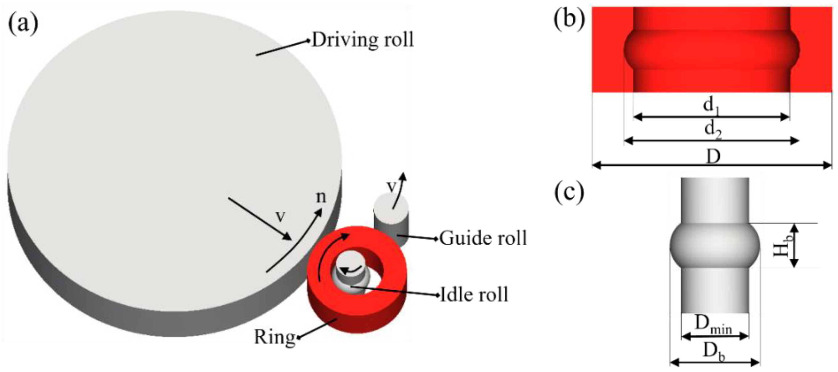
2. Hot Ring Rolling and Experimental Tests
2.1. Finite Element Simulation
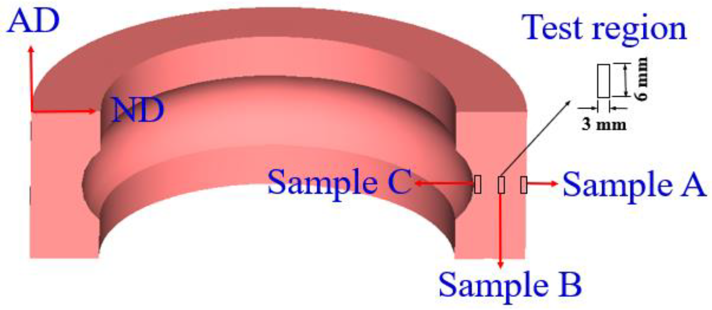
2.2. Material and Specimen Preparation
2.3. Microstructure and Mechanical Property Test
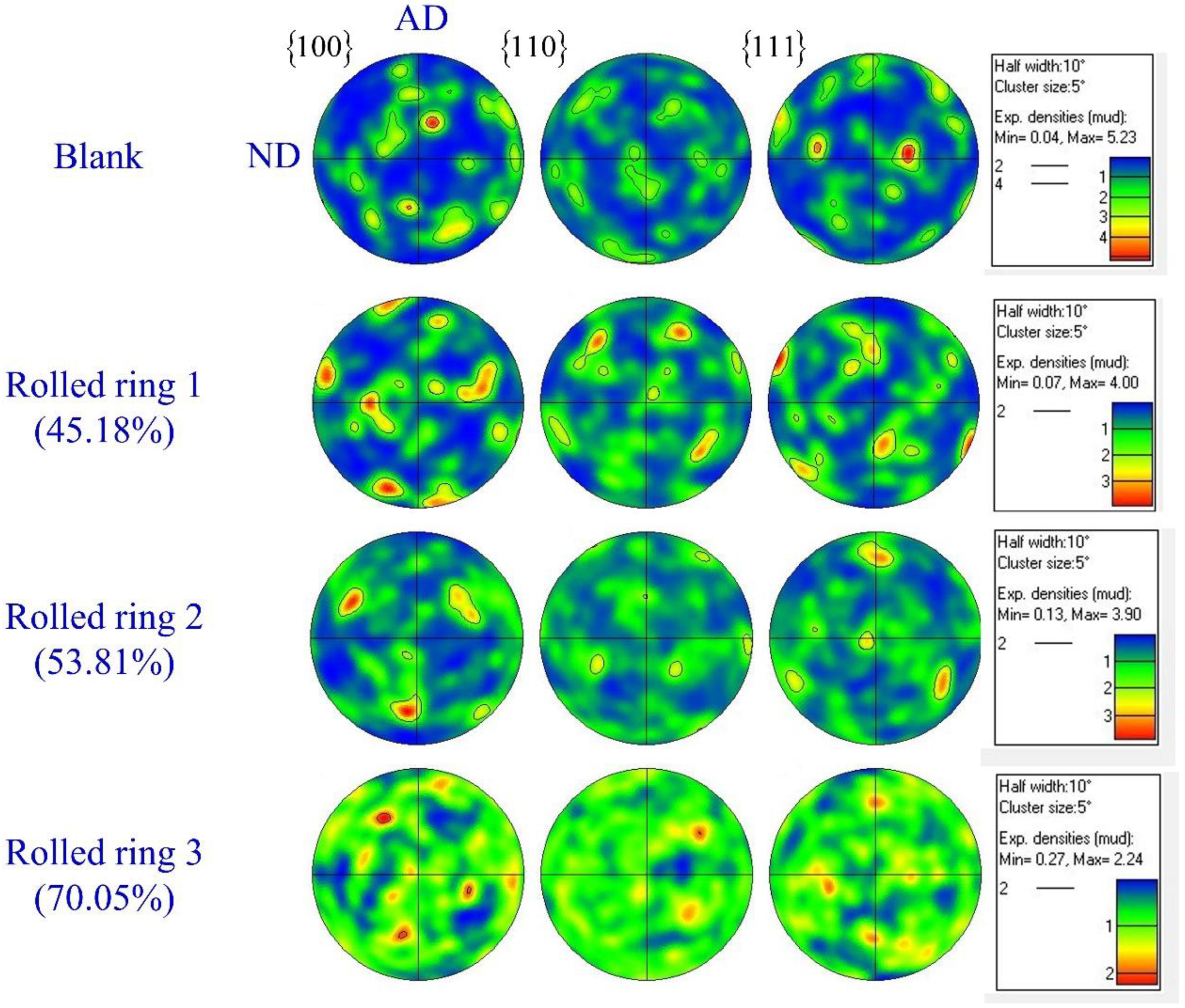
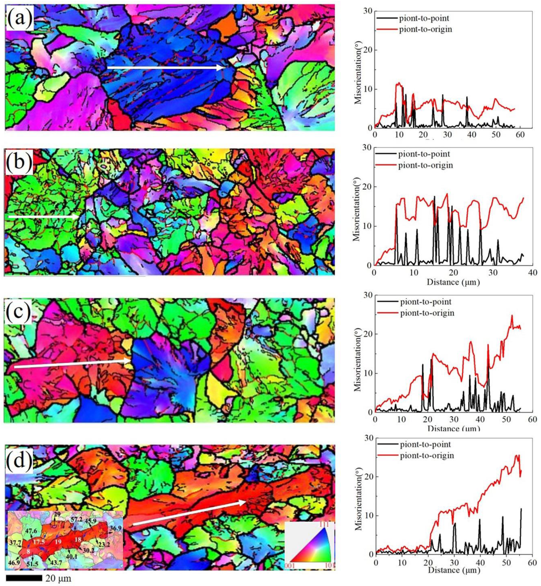
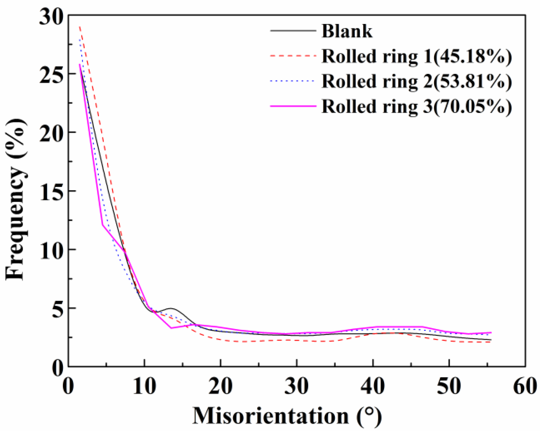
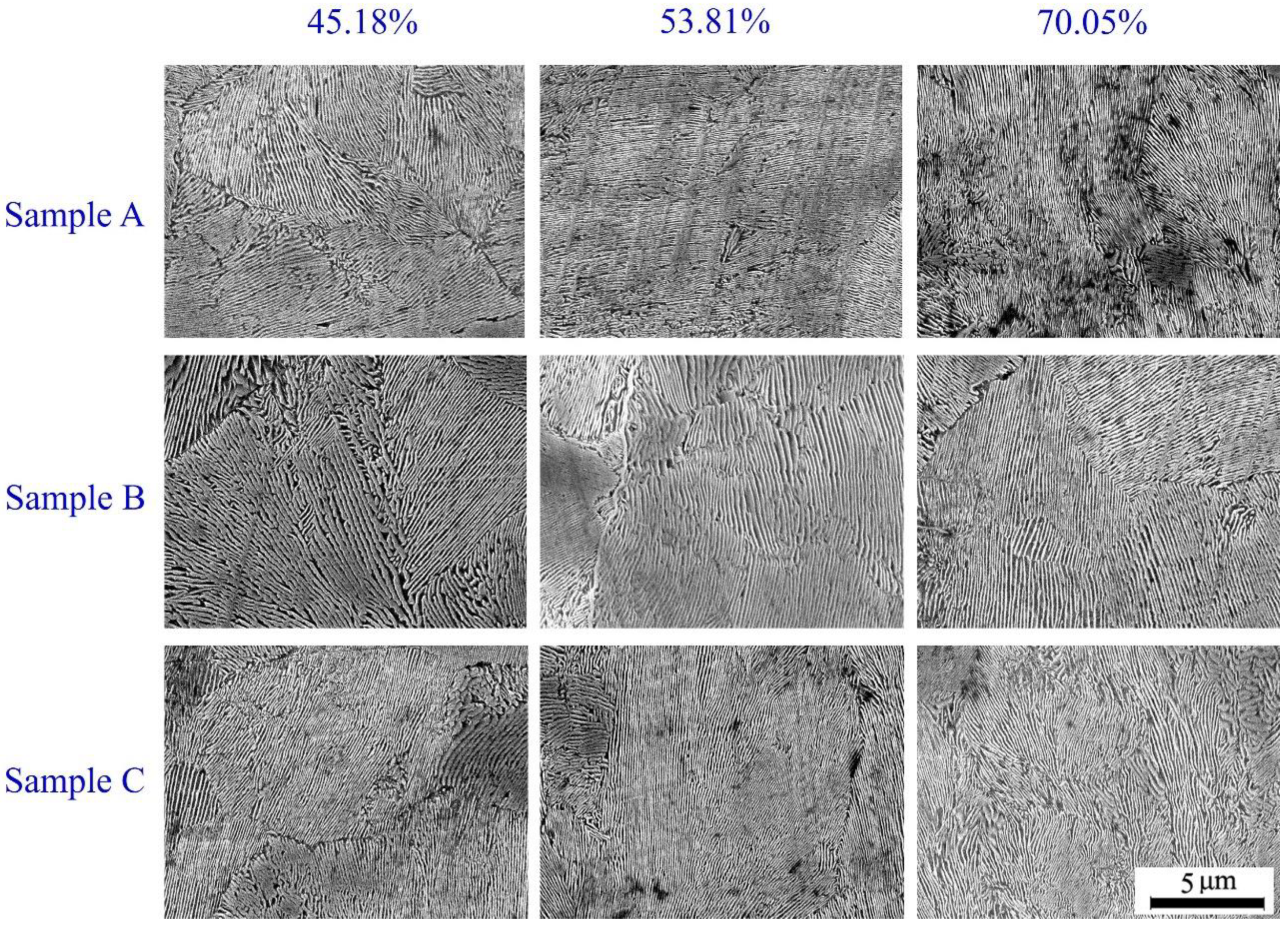
3. Results and Discussion
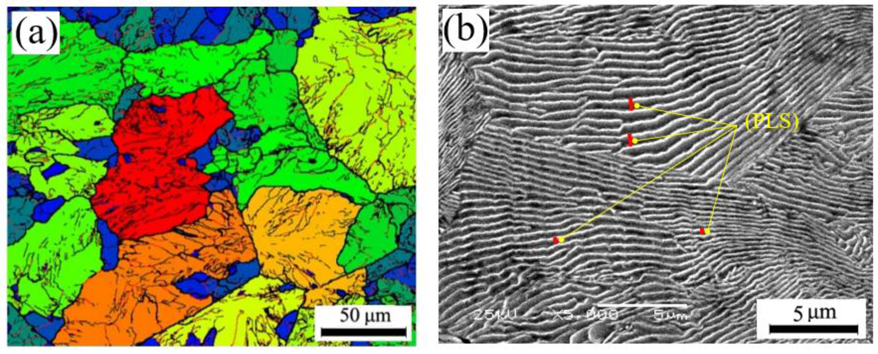
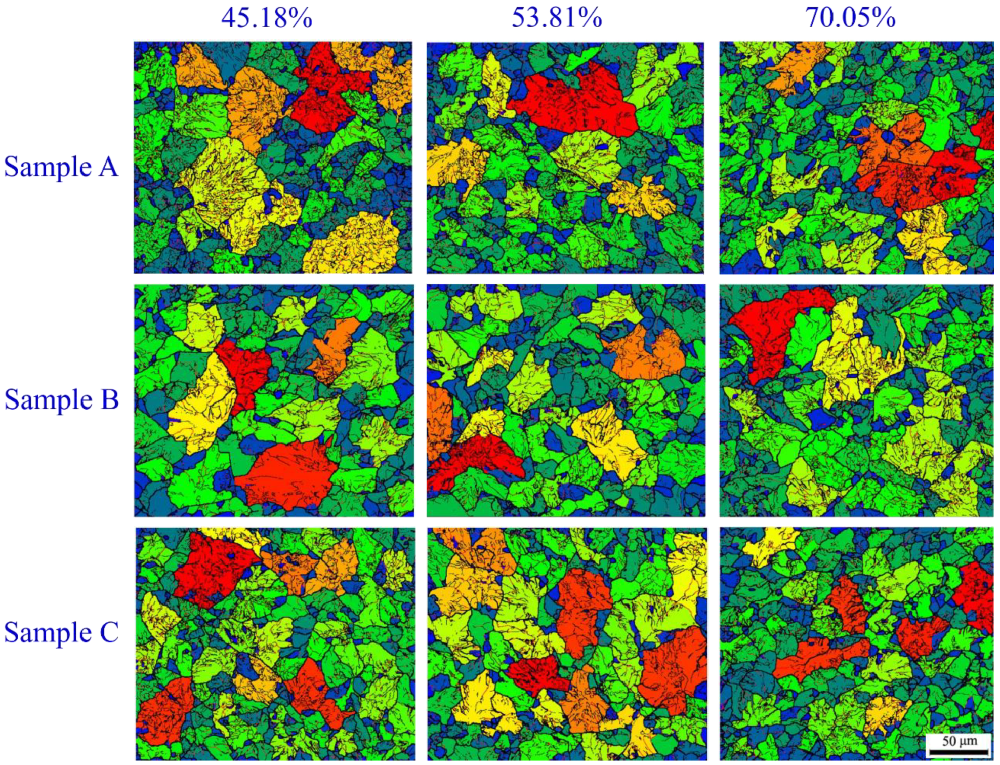
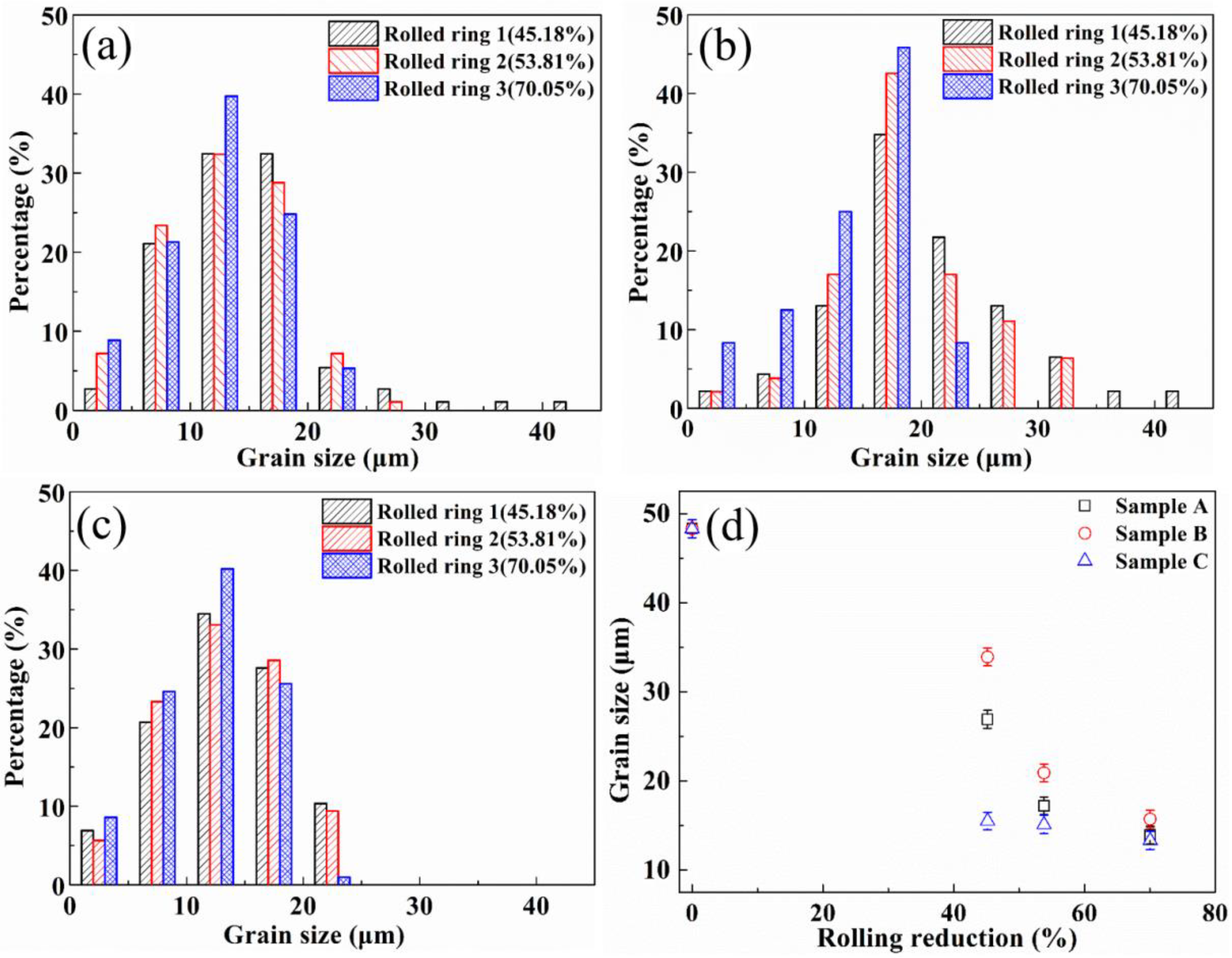
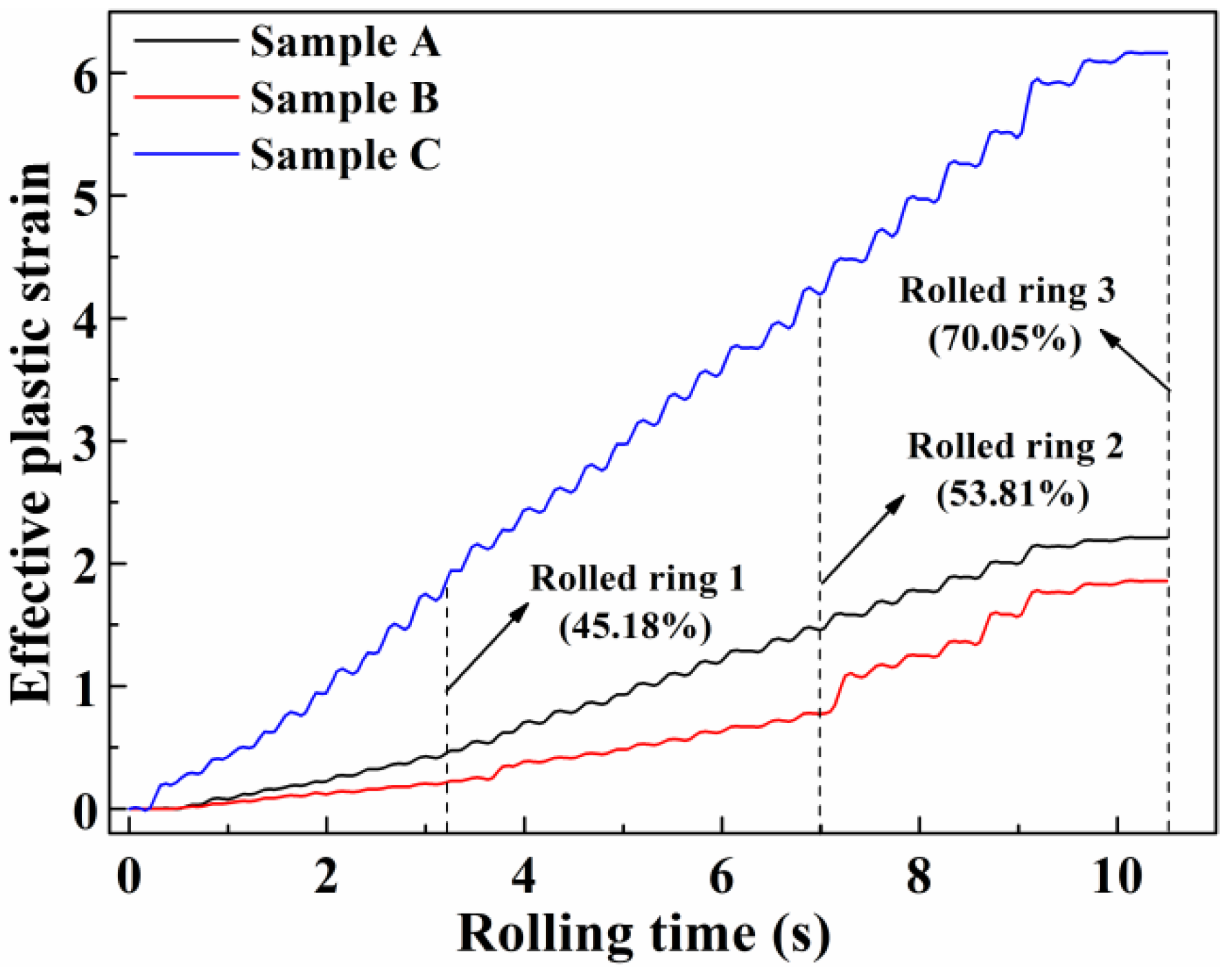
3.1. The Evolution of Grain Size Refinement
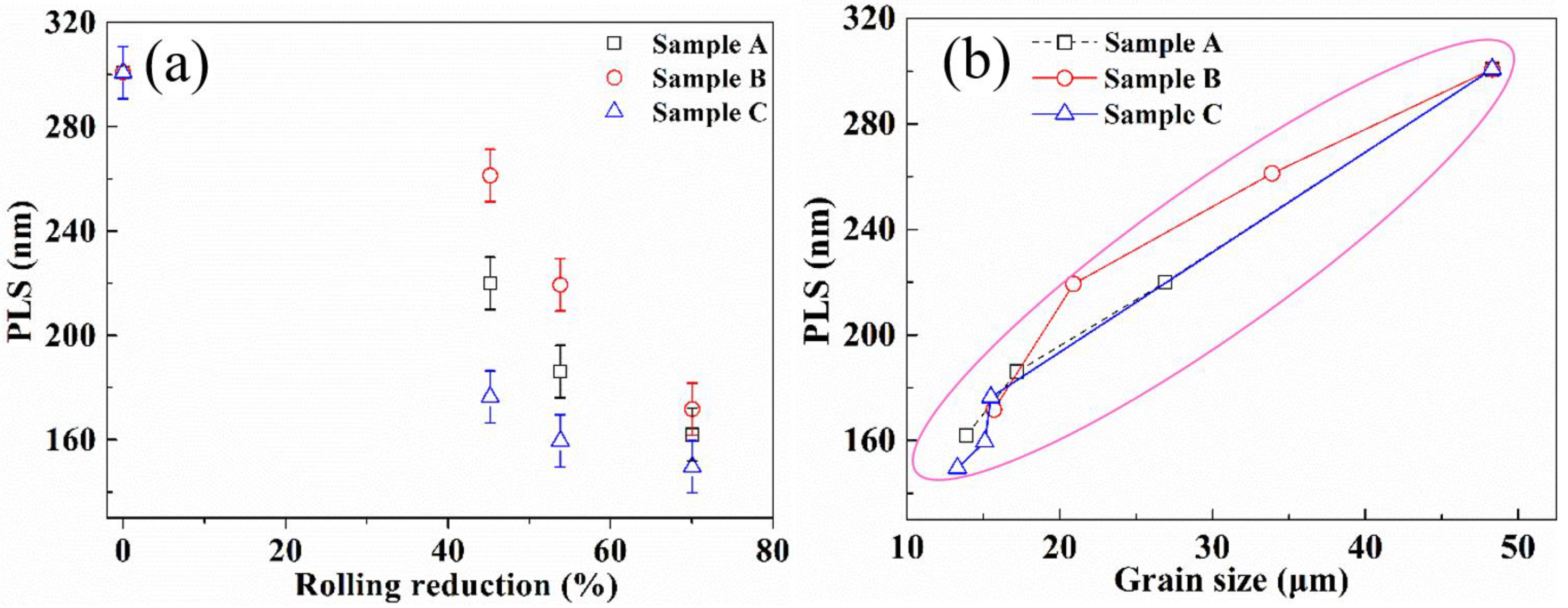
3.2. The Characteristic of Pearlite Lamellar Spacing
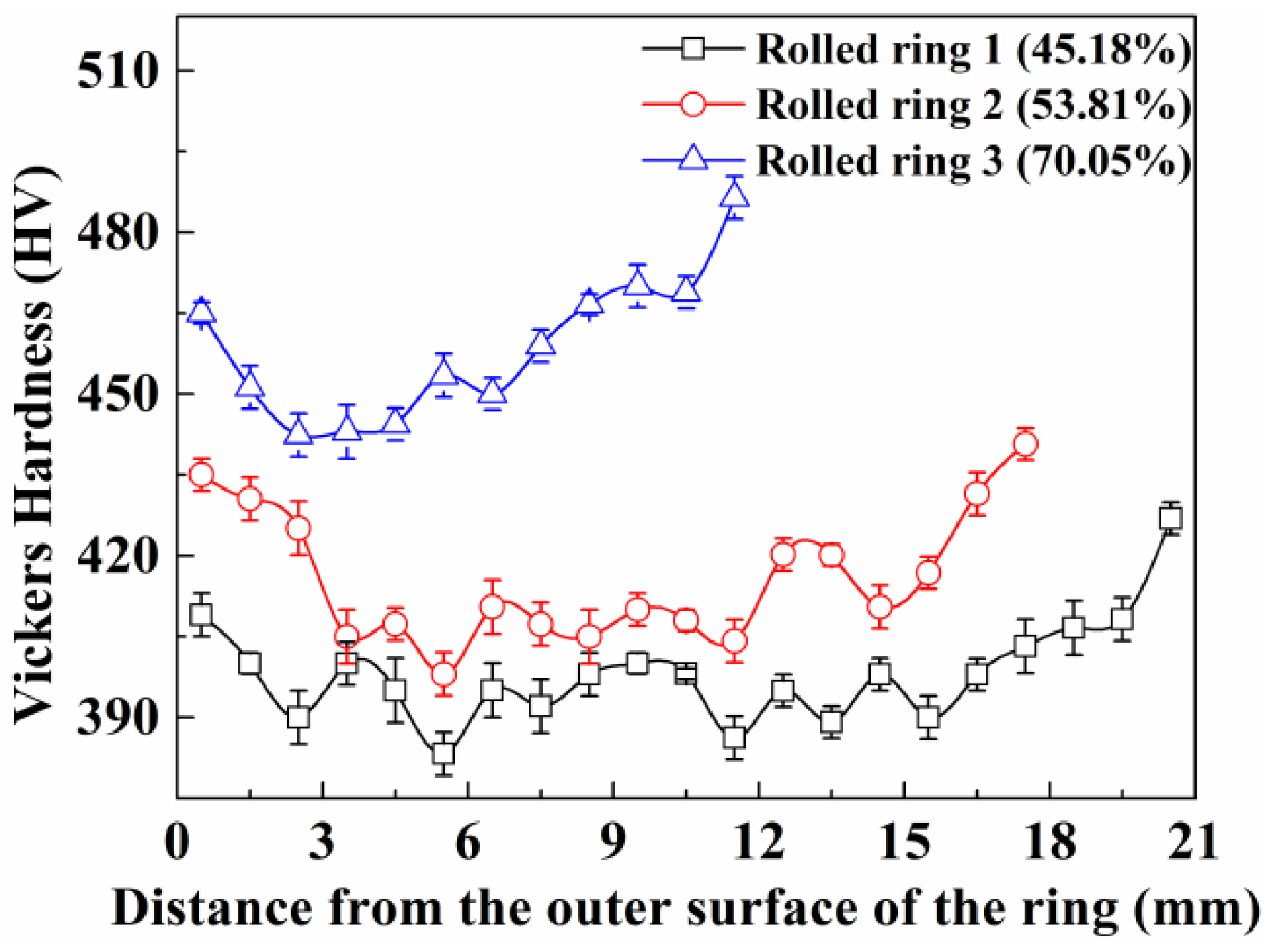
3.3. Distribution of Vickers Hardness
4. Conclusions
- The mean grain size decreased with the increase of rolling reduction. Although the rate of grain refinement at different region of the rings was different, the grain size was almost the same when the rolling reduction reached the maximum in this study. The grain refinement has been limited in 100Cr6 bearing steel during hot ring rolling. Plastic deformation changes the distribution of low- and high-angle grain boundaries and promotes the merging of lower angle to higher angle boundaries via dislocation motion by providing strong dynamic recrystallization driving force.
- The PLS and grain size have the same variation rule, and the PLS decreased with the increase of rolling reduction. Smaller grains and more grain and sub-grain boundaries provide more driving force and nucleation points for pearlite formation. The finer PLS can be acquired from the finer-grained samples.
- The thinner PLS and finer grain size can help in improving the Vickers hardness. Due to the non-uniform plastic deformation at different regions in the rings, the Vickers hardness distribution was asymmetrical u-shaped, and increased with the increase of rolling reduction.
Author Contributions
Funding
Acknowledgments
Conflicts of Interest
References
- Song, J.L.; Dowson, A.L.; Jacobs, M.H.; Brooks, J.; Beden, I. Coupled thermo-mechanical finite-element modelling of hot ring rolling process. J. Mater. Process. Technol. 2002, 121, 332–340. [Google Scholar] [CrossRef]
- Kim, K.H.; Suk, H.G.; Huh, M.Y. Development of the profile ring rolling process for large slewing rings of alloy steels. J. Mater. Process. Technol. 2007, 187, 730–733. [Google Scholar] [CrossRef]
- Hua, L.; Zhao, Z.Z. The extremum parameters in ring rolling. J. Mater. Process. Techol. 1997, 69, 273–276. [Google Scholar]
- Hua, L.; Pan, L.B.; Lan, J. Researches on the ring stiffness condition in radial-axial ring rolling. J. Mater. Process. Technol. 2009, 209, 2570–2575. [Google Scholar] [CrossRef]
- Hua, L.; Qian, D.S.; Pan, L.B. Deformation behaviors and conditions in L-section profile cold ring rolling. J. Mater. Process. Techol. 2009, 209, 5087–5096. [Google Scholar] [CrossRef]
- Qian, D.S.; Hua, L. Blank design optimization for stepped-section profile ring rolling. Sci. Chin. Technol. Sci. 2010, 53, 1612–1619. [Google Scholar] [CrossRef]
- Hua, L.; Deng, J.D.; Qian, D.S.; Lan, J.; Long, H. Modeling and application of ring stiffness condition for radial-axial ring rolling. Int. J. Mach. Tools Manuf. 2016, 110, 69–79. [Google Scholar] [CrossRef]
- Yang, H.; Wang, M.; Guo, L.G.; Sun, Z.C. 3D coupled thermo-mechanical FE modeling of blank size effects on the uniformity of strain and temperature distributions during hot rolling of titanium alloy large rings. Comput. Mater. Sci. 2008, 44, 611–621. [Google Scholar] [CrossRef]
- Yeom, J.T.; Kim, J.H.; Park, N.K.; Choi, S.S.; Lee, C.S. Ring-rolling design for a large-scale ring product of Ti-6Al-4V alloy. J. Mater. Process. Techol. 2007, 187, 747–751. [Google Scholar] [CrossRef]
- Zhu, X.L.; Liu, D.; Yang, Y.H.; Hu, Y.; Liu, G.W.; Wang, Y.N. Effects of blank dimension on forming characteristics during conical-section ring rolling of Inco718 alloy. Int. J. Adv. Manuf. Technol. 2016, 84, 2707–2718. [Google Scholar] [CrossRef]
- Yin, F.; Hua, L.; Mao, H.J.; Han, X.H. Constitutive modeling for flow behavior of GCr15 steel under hot compression experiments. Mater. Design 2013, 43, 393–401. [Google Scholar] [CrossRef]
- Yin, F.; Hua, L.; Mao, H.J.; Han, X.H.; Qian, D.S.; Zhang, R. Microstructural modeling and simulation for GCr15 steel during elevated temperature deformation. Mater. Design 2014, 55, 560–573. [Google Scholar] [CrossRef]
- Gu, S.D.; Zhang, L.W.; Yue, C.X.; Ruan, J.H.; Zhang, J.L.; Gao, H.J. Multi-field coupled numerical simulation of microstructure evolution during the hot rolling process of GCr15 steel rod. Comput. Mater. Sci. 2011, 50, 1951–1957. [Google Scholar] [CrossRef]
- Deng, S.; Qian, D.S. Grain refinement-plastic deformation-texture of bearing ring blank in cold ring rolling. J. Mech. Sci. Technol. 2017, 31, 2965–2973. [Google Scholar] [CrossRef]
- Guo, J.; Qian, D.S.; Deng, J.D. Grain refinement limit during hot radial ring rolling of as-cast GCr15steel. J. Mater. Process. Technol. 2016, 231, 151–161. [Google Scholar] [CrossRef]
- Gembalova, P.; Boruta, J.; Grycz, E.; Cmiel, M. Hot forming parameters research of bearing steel. Arch. Civil Mech. Eng. 2007, 7, 21–28. [Google Scholar] [CrossRef]
- Ryttberg, K.; Wedel, M.K.; Recina, V.; Dahlman, P.; Nyborg, L. The effect of cold ring rolling on the evolution of microstructure and texture in 100Cr6 steel. Mater. Sci. Eng. A 2010, 527, 2431–2436. [Google Scholar] [CrossRef]
- Ryttberg, K.; Wedel, M.K.; Dahlman, P.; Nyborg, L. Microstructural evolution during fracture induced by high strain rate deformation of 100Cr6 steel. J. Mater. Process. Techol. 2009, 209, 3325–3334. [Google Scholar] [CrossRef]
- Zhang, D.; Liu, Y.Z.; Zhou, L.Y.; Han, Q.; Jiang, B.; Li, Z.Z. Dynamic recrystallization behavior of GCr15SiMn bearing steel during hot deformation. J. Iron Steel Res. 2014, 21, 1042–1048. [Google Scholar] [CrossRef]
- Huo, Y.M.; He, T.; Chen, S.S.; Ji, H.C.; Wu, R.M. Microstructure evolution and unified constitutive equations for the elevated temperature deformation of SAE 52100 bearing steel. J. Manuf. Process. 2019, 44, 113–124. [Google Scholar] [CrossRef]
- Qian, D.S.; Deng, J.D.; He, S. Precision rolling methods for groove-section ring based on different contact and feed mode. Int. J. Adv. Manuf. Technol. 2018, 95, 3953–3968. [Google Scholar] [CrossRef]
- Deng, J.D.; Mao, H.J. A blank optimization design method for three-roll cross rolling of complex-groove and small-hole ring. Int. J. Mech. Sci. 2015, 93, 218–228. [Google Scholar] [CrossRef]
- Deng, S.; Hua, L. Influence of hot ring rolling on uniform deformation of High-speed rail bearing ring. Procedia Eng. 2017, 207, 1218–1223. [Google Scholar] [CrossRef]
- Mittemeijer, E.J. Fundamentals of Materials Science: The Microstructure-Property Relationship Using Metals as Model Systems, 1st ed.; Springer: Berlin/Heidelberg, Germany, 2010. [Google Scholar]
- Hua, L.; Qian, D.S.; Pan, L.B. Analysis of plastic penetration in process of groove ball-section ring rolling. J. Mech. Sci. Technol. 2008, 22, 1374–1382. [Google Scholar] [CrossRef]
- Rao, K.P.; Oruganti, R.K. Study of hot deformation through energy storage concept. J. Mater. Process. Techol. 2003, 138, 97–101. [Google Scholar] [CrossRef]
- Storojeva, L.; Ponge, D.; Kaspar, R.; Raabe, D. Development of microstructure and texture of medium carbon steel during heavy warm deformation. Acta Mater. 2004, 52, 2209–2220. [Google Scholar] [CrossRef]
- Lin, D.L.; Hu, J.; Jiang, D.M. Superplasticity of Ni-rich single phase NiAl intermetallics with large grains. Intermetallics 2005, 13, 343–349. [Google Scholar] [CrossRef]
- Xie, H.R.; Lin, D.L.; Chai, Y.T.; Hu, J. EBSD investigation on the evolution of microstructure and grain boundaries in coarse-grained Ni–48Al upon large deformation at elevated temperature. Intermetallics 2015, 58, 98–102. [Google Scholar] [CrossRef]
- Xu, P.W.; Liang, Y.; Li, J.; Meng, C. Further improvement in ductility induced by the refined hierarchical structures of pearlite. Mater. Sci. Eng. A 2019, 745, 176–184. [Google Scholar] [CrossRef]
- Chokshi, A.H. Grain Boundary Processes in Strengthening, Weakening, and Superplasticity. Adv. Eng. Mater. 2019, 22, 1900748. [Google Scholar] [CrossRef]
- Galindo-Nava, E.I.; Rivera-Diaz-del-Castillo, P.E.J. Understanding the factors controlling the hardness in martensitic steels. Scr. Mater. 2016, 110, 96–100. [Google Scholar] [CrossRef]
- Pavlina, E.J.; Van Tyne, C.J. Correlation of Yield Strength and Tensile Strength with Hardness for Steels. J. Mater. Eng. Perf. 2008, 17, 888–893. [Google Scholar] [CrossRef]
- Chakraborty, J.; Bhattacharjee, D.; Manna, I. Development of ultrafine bainite + martensite duplex microstructure in SAE 52100 bearing steel by prior cold deformation. Scr. Mater. 2009, 61, 604–607. [Google Scholar] [CrossRef]


| Rolls and Ring | Parameters | Values and Units |
|---|---|---|
| Driven roll | Outer diameter | 570 (mm) |
| Rotation speed (n) | 7.54 (rad/s) | |
| Feeding speed (v) | 3 (mm/s) | |
| Idle roll | Min diameter (Dmin) | 50 (mm) |
| Max diameter (Db) | 66 (mm) | |
| The height of groove ball (Hb) | 32.75 (mm) | |
| Guide roll | Outer diameter | 60 (mm) |
| Ring | Test temperature | 1050 (°C) |
| Friction coefficient between the rolls and ring | 0.4 |
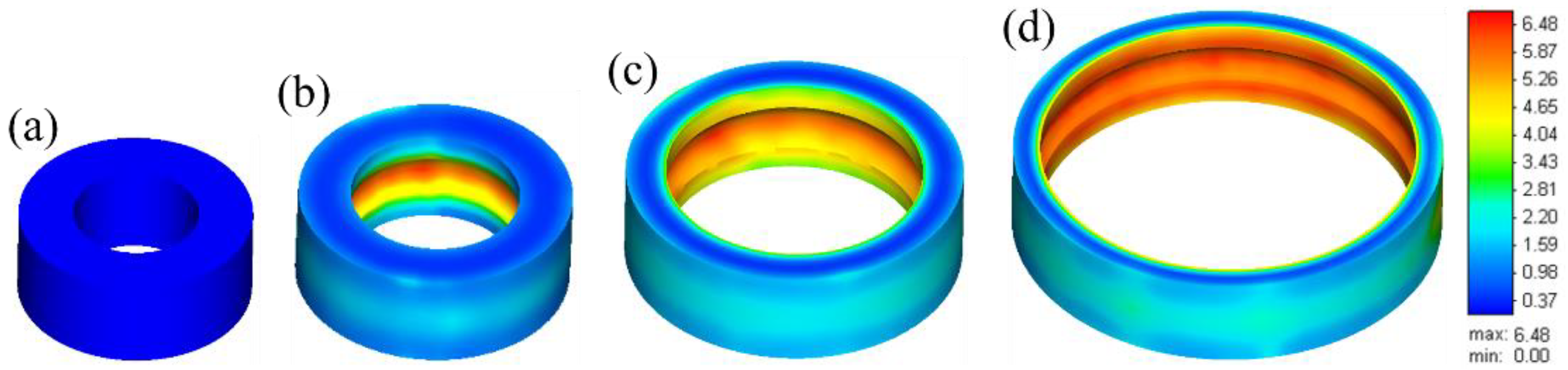
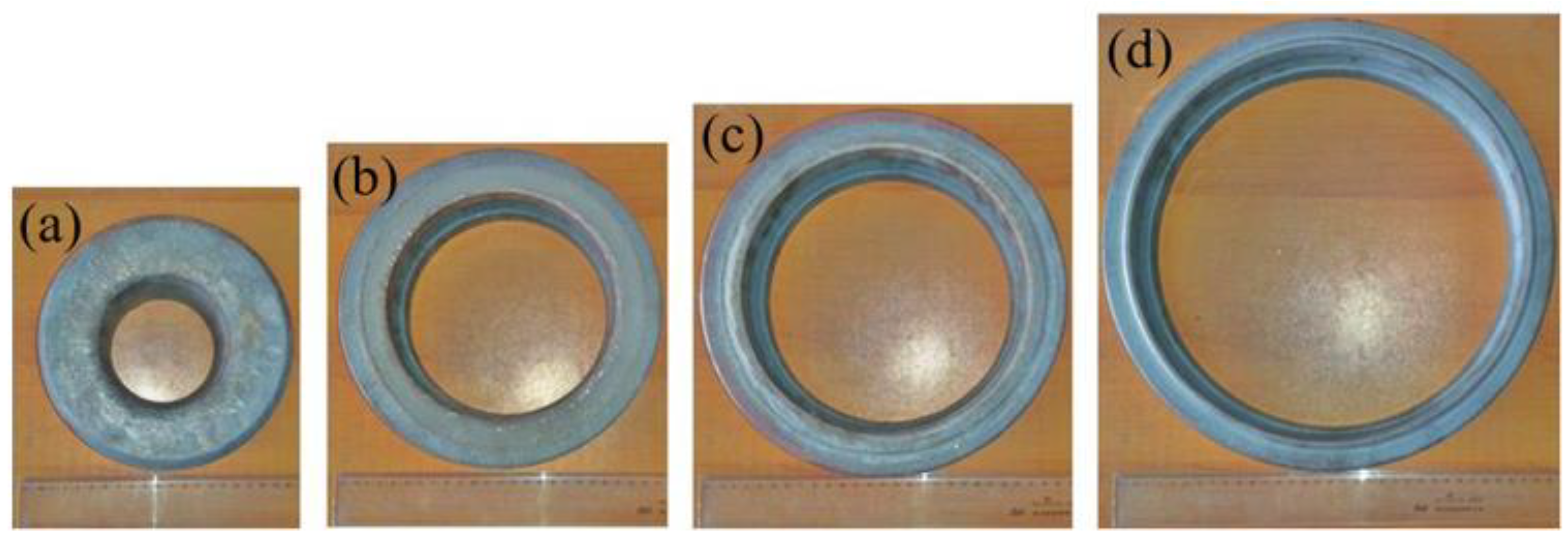
| Rings | Experimental Value (mm) | Simulative Value (mm) | Error of the Outer Diameter | ||||
|---|---|---|---|---|---|---|---|
| D | d1 | d2 | D | d1 | d2 | ||
| Blank | 170.4 | 91.6 | - | 170.4 | 91.6 | - | - |
| Rolled ring 1 | 217.5 | 158.3 | 174.3 | 215.5 | 156.9 | 173.3 | 0.92% |
| Rolled ring 2 | 239.8 | 187.4 | 203.4 | 238.6 | 186.3 | 201.1 | 0.50% |
| Rolled ring 3 | 312.9 | 273.3 | 289.3 | 313.6 | 274.3 | 290.6 | 0.22% |
| Misorientation | Frequency (%) | |||
|---|---|---|---|---|
| Blank | Rolled Ring 1 (45.18%) | Rolled Ring 2 (53.81%) | Rolled Ring 3 (70.05%) | |
| <5° | 42.7 | 49.0 | 40.5 | 37.9 |
| 5–10° | 12.7 | 13.1 | 12.6 | 14.8 |
| 10–15° | 5.7 | 4.4 | 4.5 | 3.3 |
| >15° | 38.7 | 33.3 | 41.7 | 43.7 |
© 2020 by the authors. Licensee MDPI, Basel, Switzerland. This article is an open access article distributed under the terms and conditions of the Creative Commons Attribution (CC BY) license (http://creativecommons.org/licenses/by/4.0/).
Share and Cite
Zhou, G.; Wei, W.; Liu, Q. Influence of Plastic Deformation on Microstructural Evolution of 100Cr6 Bearing Ring in Hot Ring Rolling. Materials 2020, 13, 4355. https://doi.org/10.3390/ma13194355
Zhou G, Wei W, Liu Q. Influence of Plastic Deformation on Microstructural Evolution of 100Cr6 Bearing Ring in Hot Ring Rolling. Materials. 2020; 13(19):4355. https://doi.org/10.3390/ma13194355
Chicago/Turabian StyleZhou, Guanghua, Wenting Wei, and Qinglong Liu. 2020. "Influence of Plastic Deformation on Microstructural Evolution of 100Cr6 Bearing Ring in Hot Ring Rolling" Materials 13, no. 19: 4355. https://doi.org/10.3390/ma13194355
APA StyleZhou, G., Wei, W., & Liu, Q. (2020). Influence of Plastic Deformation on Microstructural Evolution of 100Cr6 Bearing Ring in Hot Ring Rolling. Materials, 13(19), 4355. https://doi.org/10.3390/ma13194355