Microstructural Investigations of Ni-Based Superalloys by Directional Solidification Quenching Technique

 ,
,
Abstract
1. Introduction
2. Materials and Methods
3. Results and Discussion
3.1. Solidification Sequence of the Formed Phases
- Crystallization of γ matrix: at 1476.88–1521.15 K characterized by dendrite tips as seen in Figure 2a. According to the liquidus temperatures of 1610 K (CMSX-6 and CMSX-6+0.03C) and 1652 K (MAR-M247), the existence of undercooling by 103.27–134.26 K is evident since crystallization was initiated bellow the supposed temperatures.
- Solidification of fine equiaxed carbides in the interdendritic area: at 1442.58–1496.56 K.
3.2. Shrinkage Porosity
3.3. Carbide Solidification at Different Compositions and Rates
3.3.1. Fraction
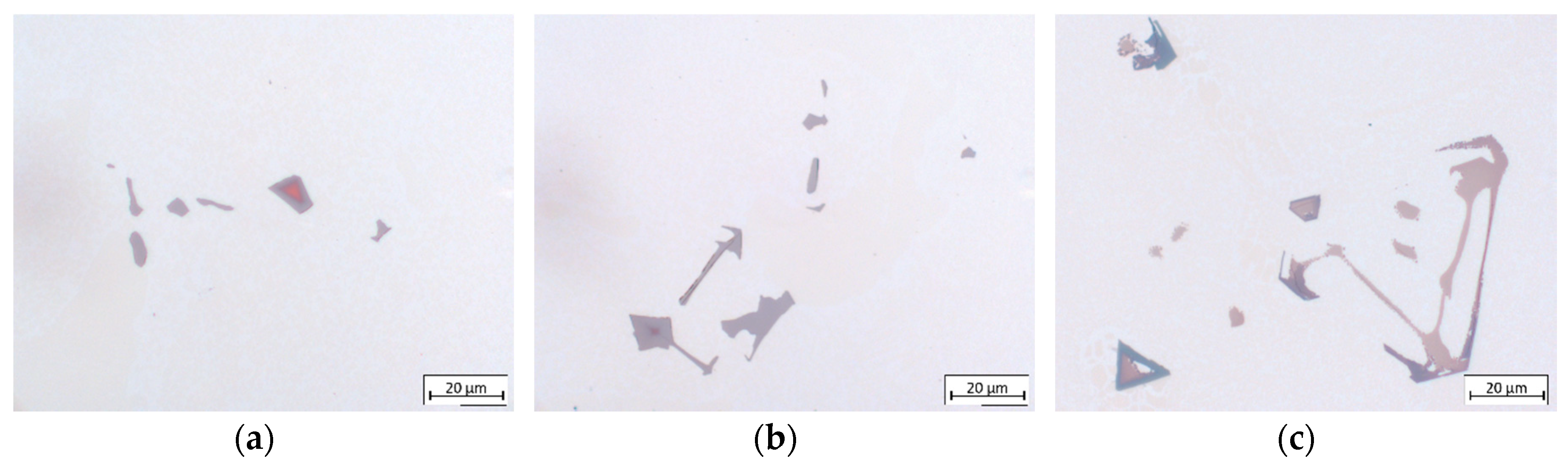
3.3.2. Morphology
3.3.3. Chemical Composition
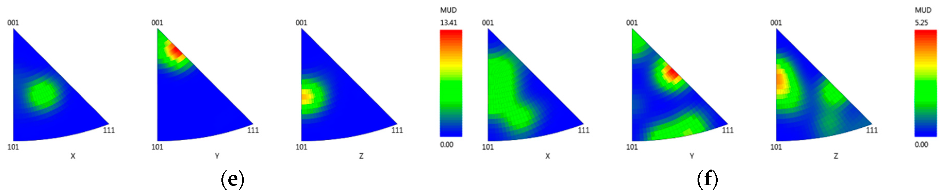
3.3.4. Crystallographic Orientation
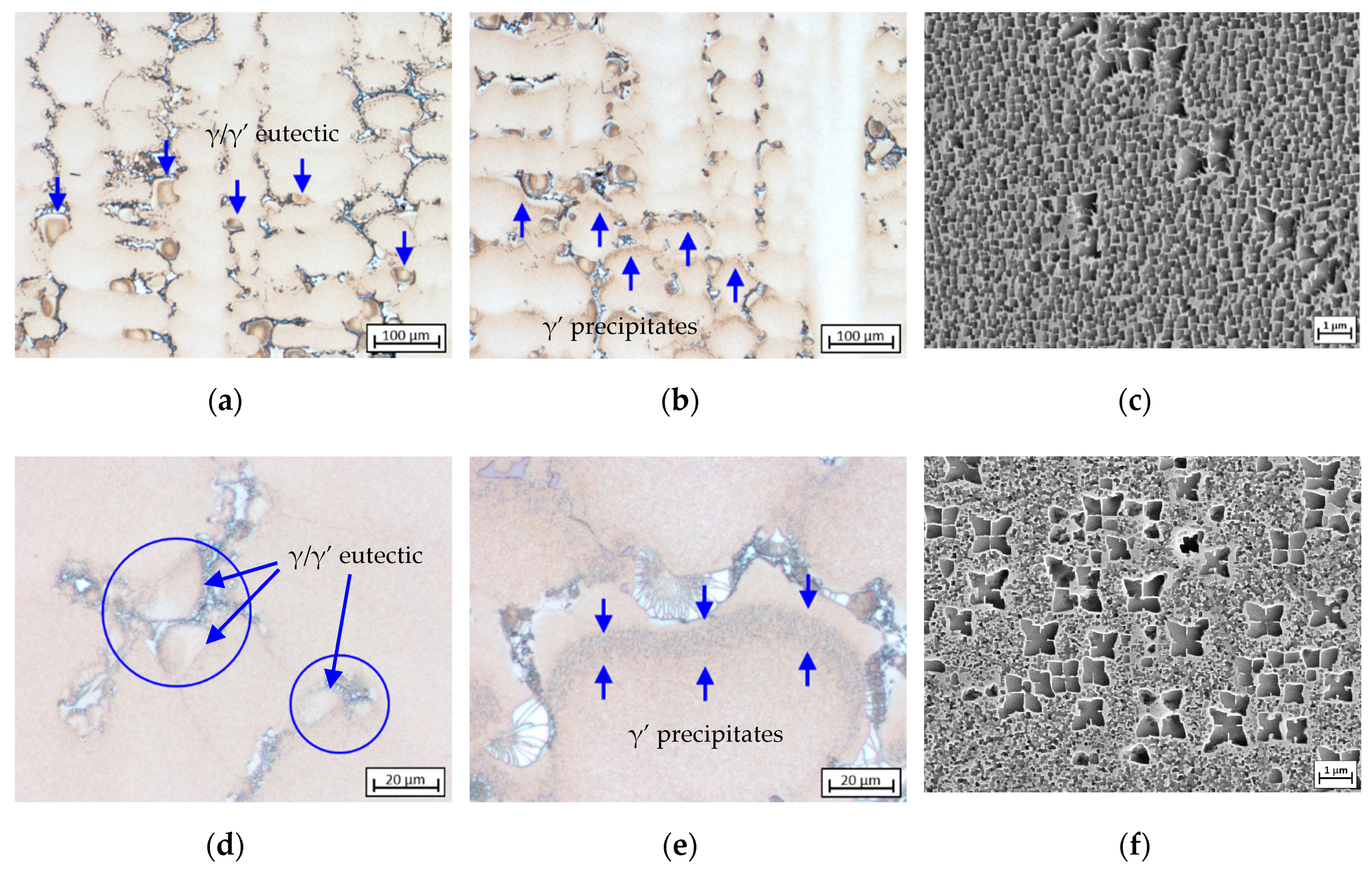
3.4. Formation and Crystallographic Analysis of γ/γ’ Eutectic
3.5. Volume Fraction and Morphology of γ’ Precipitates
4. Conclusions
- The solidification sequence of CMSX-6, CMSX-6+0.03C and MAR-M247 begins with the crystallization of γ, which can be described by at 1476.88–1521.15 K. Besides the primary dendrites, some equiaxed carbides are observed in the interdendritic region, indicating the direct growth of carbides from the melt through the reaction at 1442.58–1496.56 K. Subsequently, the formation of the γ/γ’ eutectic proceeds via both eutectic and peritectic reactions at 1418.26–1472.56 K. The last forming phase is γ’, which forms by means of solid-state phase transformation reaction from at 1405.68–1470.29 K.
- An increase in carbon content causes and intensifying porosity for both applied cooling rates. Nevertheless, the porosity amount at the higher cooling rate is rather toned down to a smaller fraction of carbides formed. The presence of carbides in the interdendritic area notably reduces its permeability which hinders the melt flow.
- EDX analysis indicates that the carbides found in this study mainly correspond to the MC-type, whereby M is dominated by Ti and Ta. At higher carbon concentrations and/or lower cooling rates, the first carbides to precipitate are orangish in color and rich in Ti, which are later on enveloped by a bluish gray overlay loaded with Ta and Mo. In MAR-M247 samples, the carbides observed are rich in Ta, W and Hf, having a purplish gray color. The carbide morphology changes from faceted to Chinese script-type for increasing carbon concentration respective to cooling rate. The size and fraction of the carbides decrease with increasing cooling rate, but the carbide fraction is primarily governed by the carbon content of the alloy. A greater tendency for carbide misorientation and, hence, the presence of local polycrystalline structures can be observed at higher cooling rates. Accordingly, the single crystalline character of the alloy is retained better, applying lower cooling rates.
- The growth direction of γ/γ’ eutectic begins with the fine γ/γ’ lamellar core as it was found prior to the coarse γ/γ’ structure. The fine eutectic core is crystallized by means of a eutectic reaction, followed by a progressive transition to growth of the coarse structure. The growth continues until it comes into contact with other eutectic islands or a neighboring primary γ dendrite. Crystallographic analysis on CMSX-6+0.03C samples indicates that there is no evidence of homogeneous nucleation of γ/γ’ eutectic. The eutectic islands nucleate on the surface of γ dendrites, and thus the eutectic adopts the crystal structure of the dendrite. A small eutectic island observed to have the same orientation as a carbide but a different orientation from the dendrite confirms that γ/γ’ eutectic does not only nucleate on the dendrite lobe but also on the carbide surface.
- Increasing cooling rate leads to finer and denser γ’ precipitates. The γ’ volume fraction is influenced by γ’ FEs, but the effect is slightly depleted by the presence of carbon. Carbon bonds γ’ FEs to form carbides in the interdendritic area so that the γ’ FEs are consumed while γ dendrites are growing. The solidified γ dendrite just before γ’ precipitation becomes more depleted in γ’ FEs as carbon level in the alloy increases and thus the γ’ volume fraction decreases.
Author Contributions
Funding
Acknowledgments
Conflicts of Interest
References
- Basuki, E.A. Paduan Logam untuk Aplikasi Temperatur Tinggi dan Penghematan Energi; ITB: Bandung, Indonesia, 2016; p. 486. [Google Scholar]
- Donachie, M.J.; Donachie, S.J. Superalloys: A Technical Guide; ASM International: Russell, OH, USA, 2002. [Google Scholar]
- Dreshfield, R.L. Defects in Nickel-Base Superalloys. JOM 1987, 39, 16–21. [Google Scholar] [CrossRef]
- Reed, R.C. The Superalloys-Fundamentals and Applications; Cambridge University Press: Cambridge, UK, 2008. [Google Scholar]
- Caron, P.; Khan, T. Evolution of Ni-based superalloys for single crystal gas turbine blade applications. Aerosp. Sci. Technol. 1999, 3, 513–523. [Google Scholar] [CrossRef]
- Erickson, G.L. A new, third-generation, single-crystal, casting superalloy. JOM 1995, 47, 36–39. [Google Scholar] [CrossRef]
- Kawagishi, K.; Yeh, A.-C.; Yokokawa, T.; Kobayashi, T.; Koizumi, Y.; Harada, H. Development of an Oxidation-Resistant High-Strength Sixth-Generation Single-Crystal Superalloy TMS-238. In Superalloys 2012; John Wiley & Sons, Inc.: Hoboken, NJ, USA, 2012. [Google Scholar]
- Koizumi, Y.; Osawa, M.; Kobayashi, T.; Yokokawa, T.; Zhang, J.; Harada, H.; Aoki, Y.; Arai, M. Development of Next-Generation Ni-Base Single Crystal Superalloys. J. Jpn. Inst. Met. 2004, 67, 35–43. [Google Scholar] [CrossRef]
- Sato, A.; Harada, H.; Yeh, A.-C.; Kawagishi, K.; Kobayashi, T.; Koizumi, Y.; Yokokawa, T.; Zhang, J.X. A 5th Generation SC Superalloy with Balanced High Temperature Properties and Processability. In Proceedings of the Superalloys 2008, Champion, PA, USA, 14–18 September 2008. [Google Scholar]
- Geddes, B.; Leon, H.; Huang, X. Superalloys: Alloying and Performance; ASM International: Russell, OH, USA, 2010. [Google Scholar]
- Wen, X. Investigation of the Solidification Behaviour of Ni-Based Single-Crystal Superalloys; RWTH Aachen University: Aachen, Germany, 2014. [Google Scholar]
- D’Souza, N.; Dong, H. An Analysis of Solidification Path in the Ni-Base Superalloy, CMSX10K. In Proceedings of the Superalloys 718, 625, 706 and Various Derivatives, Pittsburgh, PA, USA, 26–29 June 2008. [Google Scholar]
- Fleck, M.; Querfurth, F.; Glatzel, U. Phase field modeling of solidification in multi-component alloys with a case study on the Inconel 718 alloy. J. Mater. Res. 2017, 32, 4605–4615. [Google Scholar] [CrossRef]
- Heckl, A.; Rettig, R.; Cenanovic, S.; Göken, M.; Singer, R. Investigation of the final stages of solidification and eutectic phase formation in Re and Ru containing nickel-base superalloys. J. Cryst. Growth 2010, 312, 2137–2144. [Google Scholar] [CrossRef]
- Kang, S.-H.; Deguchi, Y.; Yamamoto, K.; Ogi, K.; Shirai, M. Solidification Process and Behavior of Alloying Elements in Ni-Based Superalloy Inconel718. Mater. Trans. 2004, 45, 2728–2733. [Google Scholar] [CrossRef][Green Version]
- Pang, H.; Dong, H.; Beanland, R.; Stone, H.J.; Rae, C.; Midgley, P.A.; Brewster, G.; D’Souza, N. Microstructure and Solidification Sequence of the Interdendritic Region in a Third Generation Single-Crystal Nickel-Base Superalloy. Met. Mater. Trans. A 2009, 40, 1660–1669. [Google Scholar] [CrossRef]
- Seo, S.M.; Lee, J.H.; Yoo, Y.S.; Jo, C.Y.; Miyahara, H.; Ogi, K. Solute Redistribution during Planar and Dendritic Growth of Directionally Solidified Ni-Base Superalloy CMSX-10. In Proceedings of the Eleventh International Symposium on Superalloys, Champion, PA, USA, 14–18 September 2008. [Google Scholar]
- Wang, F.; Ma, D.; Zhang, J.; Bogner, S.; Bührig-Polaczek, A. Solidification behavior of a Ni-based single crystal CMSX-4 superalloy solidified by downward directional solidification process. Mater. Charact. 2015, 101, 20–25. [Google Scholar] [CrossRef]
- Fernandez, R.; LeComte, J.C.; Kattamis, T.Z. Effect of solidification parameters on the growth geometry of MC carbide in IN-100 dendritic monocrystals. Met. Mater. Trans. A 1978, 9, 1381–1386. [Google Scholar] [CrossRef]
- Chen, J.; Huang, B.; Lee, J.H.; Choe, S.J.; Lee, Y.T. Carbide Formation Process in Directionally Solidified MAR-M247 LC Superalloy. J. Mater. Sci. Technol. 1999, 15, 48–52. [Google Scholar]
- Szczotok, A.; Rodak, K. Microstructural studies of carbides in MAR-M247 nickel-based superalloy. IOP Conf. Ser. Mater. Sci. Eng. 2012, 35, 012006. [Google Scholar] [CrossRef]
- Ma, D.; Sahm, P.R. Microstructural Evolution During Directional Solidification of Superalloy CMSX-6. Mater. Sci. Forum 1996, 215–216, 223–228. [Google Scholar] [CrossRef]
- Onyszko, A.; Kubiak, K.; Sieniawski, J. Turbine Blades of the Single Crystal Nickel Based CMSX-6 Superalloy. J. Achiev. Mater. Manuf. Eng. 2009, 32, 66–69. [Google Scholar]
- Wang, F.; Ma, D.; Zhang, J.; Liu, L.; Hong, J.; Bogner, S.; Bührig-Polaczek, A. Effect of solidification parameters on the microstructures of superalloy CMSX-6 formed during the downward directional solidification process. J. Cryst. Growth 2014, 389, 47–54. [Google Scholar] [CrossRef]
- Wang, F.; Bührig-Polaczek, A.; Ma, D. Eutectic Formation during Solidification of Ni-Based Single-Crystal Superalloys with Additional Carbon. Met. Mater. Trans. A 2017, 48, 5442–5448. [Google Scholar] [CrossRef]
- D’Souza, N.; Dong, H. Solidification path in third-generation Ni-based superalloys, with an emphasis on last stage solidification. Scr. Mater. 2007, 56, 41–44. [Google Scholar] [CrossRef]
- Cutler, E.; Wasson, A.; Fuchs, G. Effect of minor alloying additions on the solidification of single-crystal Ni-base superalloys. J. Cryst. Growth 2009, 311, 3753–3760. [Google Scholar] [CrossRef]
- Liu, L.R.; Jin, T.; Zhao, N.R.; Wang, Z.H.; Sun, X.F.; Guan, H.R.; Hu, Z.Q. Effect of Carbon Additions on the Microstructure in a Ni-base Single Crystal Superalloy. Mater. Lett. 2004, 58, 2290–2294. [Google Scholar] [CrossRef]
- Al-Jarba, K.A.; Fuchs, G.E. Carbon-containing single-crystal nickel-based superalloys: Segregation behavior and carbide formation. JOM 2004, 56, 50–55. [Google Scholar] [CrossRef]
- Warnken, N.; Ma, D.; Mathes, M.; Steinbach, I. Investigation of eutectic island formation in SX superalloys. Mater. Sci. Eng. A 2005, 413, 267–271. [Google Scholar] [CrossRef]
- Zhang, S. Investigation of the Influence of Carbon Content on the Microstructure of the Single-Crystalline Nickel-Based Superalloys; RWTH Aachen University: Aachen, Germany, 2019. [Google Scholar]
- Zhao, G.; Zang, X.-M.; Sun, W.-R. Role of carbon in modifying solidification and microstructure of a Ni-based superalloy with high Al and Ti contents. J. Iron Steel Res. Int. 2020, 1–13. [Google Scholar] [CrossRef]
- Tin, S.; Pollock, T.; King, W. Carbon Additions and Grain Defect Formation in High Refractory Nickel-Base Single Crystal Superalloys. Superalloys 2000, 201–210. [Google Scholar] [CrossRef]
- Chen, J.; Lee, J.; Jo, C.; Choe, S.; Lee, Y. MC carbide formation in directionally solidified MAR-M247 LC superalloy. Mater. Sci. Eng. A 1998, 247, 113–125. [Google Scholar] [CrossRef]
- Li, X.; Wang, L.; Dong, J.; Lou, L. Effect of Solidification Condition and Carbon Content on the Morphology of MC Carbide in Directionally Solidified Nickel-base Superalloys. J. Mater. Sci. Technol. 2014, 30, 1296–1300. [Google Scholar] [CrossRef]
- Yu, Z.-H.; Liu, L.; Zhang, J. Effect of carbon addition on carbide morphology of single crystal Ni-based superalloy. Trans. Nonferrous Met. Soc. China 2014, 24, 339–345. [Google Scholar] [CrossRef]
- Milenkovic, S.; Sabirov, I.; Llorca, J. Effect of the cooling rate on microstructure and hardness of MAR-M247 Ni-based superalloy. Mater. Lett. 2012, 73, 216–219. [Google Scholar] [CrossRef]
- Liu, L.; Jin, T.; Zhao, N.; Sun, X.; Guan, H.; Hu, Z. Formation of carbides and their effects on stress rupture of a Ni-base single crystal superalloy. Mater. Sci. Eng. A 2003, 361, 191–197. [Google Scholar] [CrossRef]
- Dong, X.; Zhang, X.; Du, K.; Zhou, Y.; Jin, T.; Ye, H. Microstructure of Carbides at Grain Boundaries in Nickel Based Superalloys. J. Mater. Sci. Technol. 2012, 28, 1031–1038. [Google Scholar] [CrossRef]
- Wang, F.; Ma, D.; Bogner, S.; Bührig-Polaczek, A. Influence of Processing Parameters on the Solidification Behavior of Single-Crystal CMSX-4 Superalloy. Met. Mater. Trans. A 2016, 47, 3703–3712. [Google Scholar] [CrossRef]
- Wang, F.; Xu, W.; Ma, D.; Bührig-Ploaczek, A. Co-growing mechanism of γ/γ′ eutectic on MC-type carbide in Ni-based single crystal superalloys. J. Alloys Compd. 2019, 792, 505–509. [Google Scholar] [CrossRef]
- Gottstein, G. Physical Foundations of Materials Science; Springer Science & Business Media: Berlin, Germany, 2013. [Google Scholar]
- Bürgel, R. Handbuch Hochtemperatur-Werkstofftechnik; Springer Science and Business Media LLC: Berlin, Germany, 1998. [Google Scholar]
- Fu, H.; Geng, X. High rate directional solidification and its application in single crystal superalloys. Sci. Technol. Adv. Mater. 2001, 2, 197–204. [Google Scholar] [CrossRef]
- Vyazovkin, S. Solid-Solid Phase Transition—An Overview|ScienceDirect Topics. Available online: https://www.sciencedirect.com/topics/chemistry/solid-solid-phase-transition (accessed on 19 May 2020).


| Alloy | Cr | Co | Mo | W | Al | Ti | Ta | Hf | C | B | Ni |
|---|---|---|---|---|---|---|---|---|---|---|---|
| CMSX-6 | 10 | 5 | 3 | - | 4.8 | 4.7 | 2 | 0.1 | 0.006 | - | Bal. |
| CMSX-6+0.03C | 10 | 5 | 3 | - | 4.8 | 4.7 | 2 | 0.1 | 0.03 | - | Bal. |
| MAR-M247 | 8.4 | 10 | 0.7 | 10 | 5.5 | 1 | 3 | 1.5 | 0.15 | 0.015 | Bal. |
© 2020 by the authors. Licensee MDPI, Basel, Switzerland. This article is an open access article distributed under the terms and conditions of the Creative Commons Attribution (CC BY) license (http://creativecommons.org/licenses/by/4.0/).
Share and Cite
Wittenzellner, T.; Sumarli, S.; Schaar, H.; Wang, F.; Ma, D.; Bührig-Polaczek, A. Microstructural Investigations of Ni-Based Superalloys by Directional Solidification Quenching Technique. Materials 2020, 13, 4265. https://doi.org/10.3390/ma13194265
Wittenzellner T, Sumarli S, Schaar H, Wang F, Ma D, Bührig-Polaczek A. Microstructural Investigations of Ni-Based Superalloys by Directional Solidification Quenching Technique. Materials. 2020; 13(19):4265. https://doi.org/10.3390/ma13194265
Chicago/Turabian StyleWittenzellner, Tobias, Shieren Sumarli, Helge Schaar, Fu Wang, Dexin Ma, and Andreas Bührig-Polaczek. 2020. "Microstructural Investigations of Ni-Based Superalloys by Directional Solidification Quenching Technique" Materials 13, no. 19: 4265. https://doi.org/10.3390/ma13194265
APA StyleWittenzellner, T., Sumarli, S., Schaar, H., Wang, F., Ma, D., & Bührig-Polaczek, A. (2020). Microstructural Investigations of Ni-Based Superalloys by Directional Solidification Quenching Technique. Materials, 13(19), 4265. https://doi.org/10.3390/ma13194265