Comparative Research on Tensile Properties of Cement–Emulsified Asphalt–Standard Sand (CAS) Mortar and Cement–Emulsified Asphalt–Rubber Particle (CAR) Mortar


Abstract
:1. Introduction
2. Materials and Methods
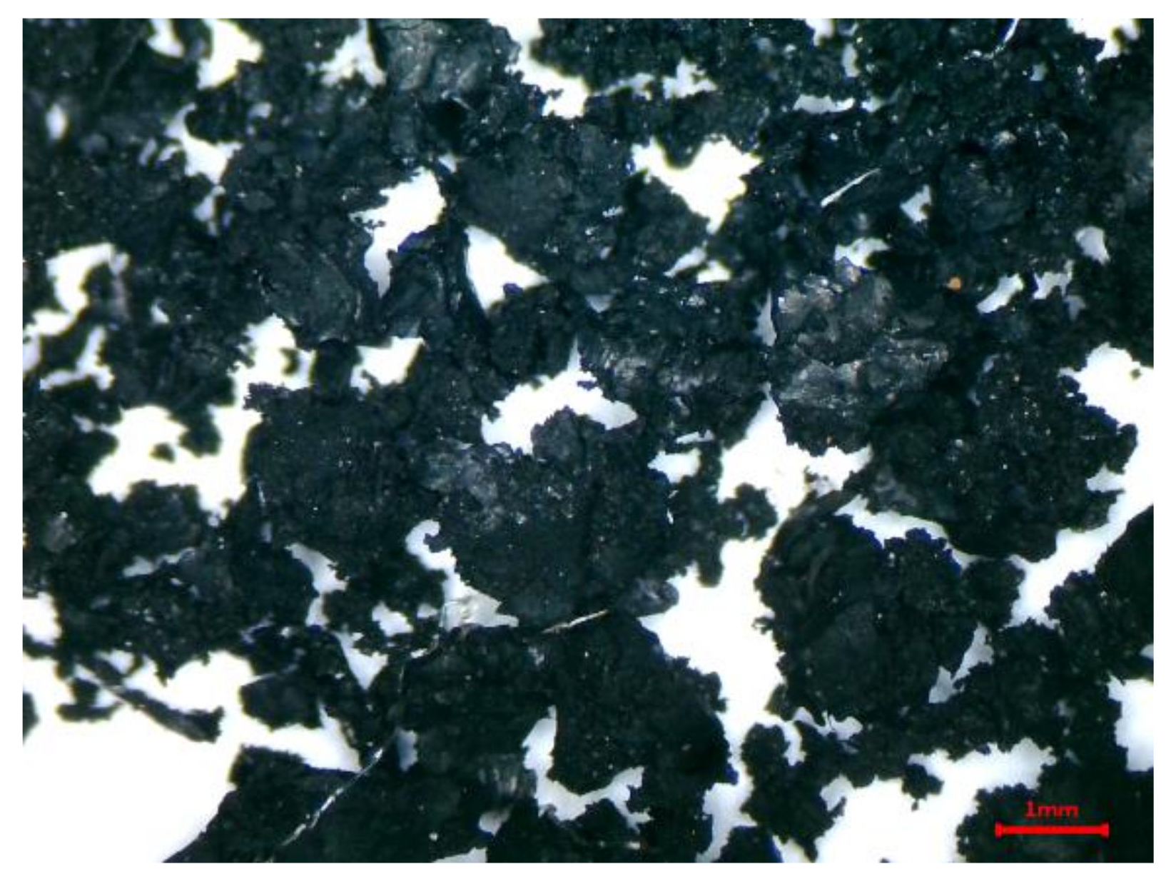
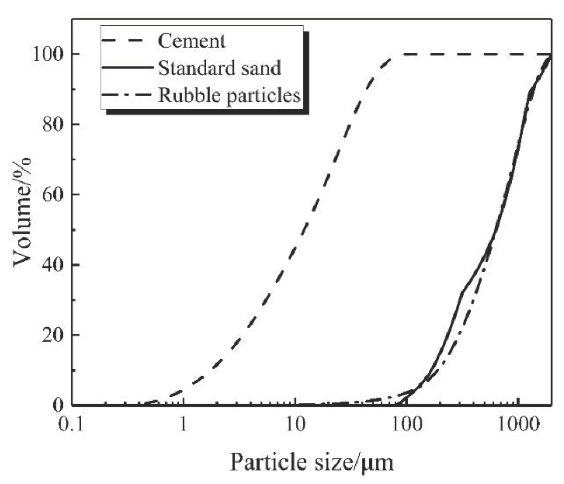
2.1. Materials
2.2. Methods
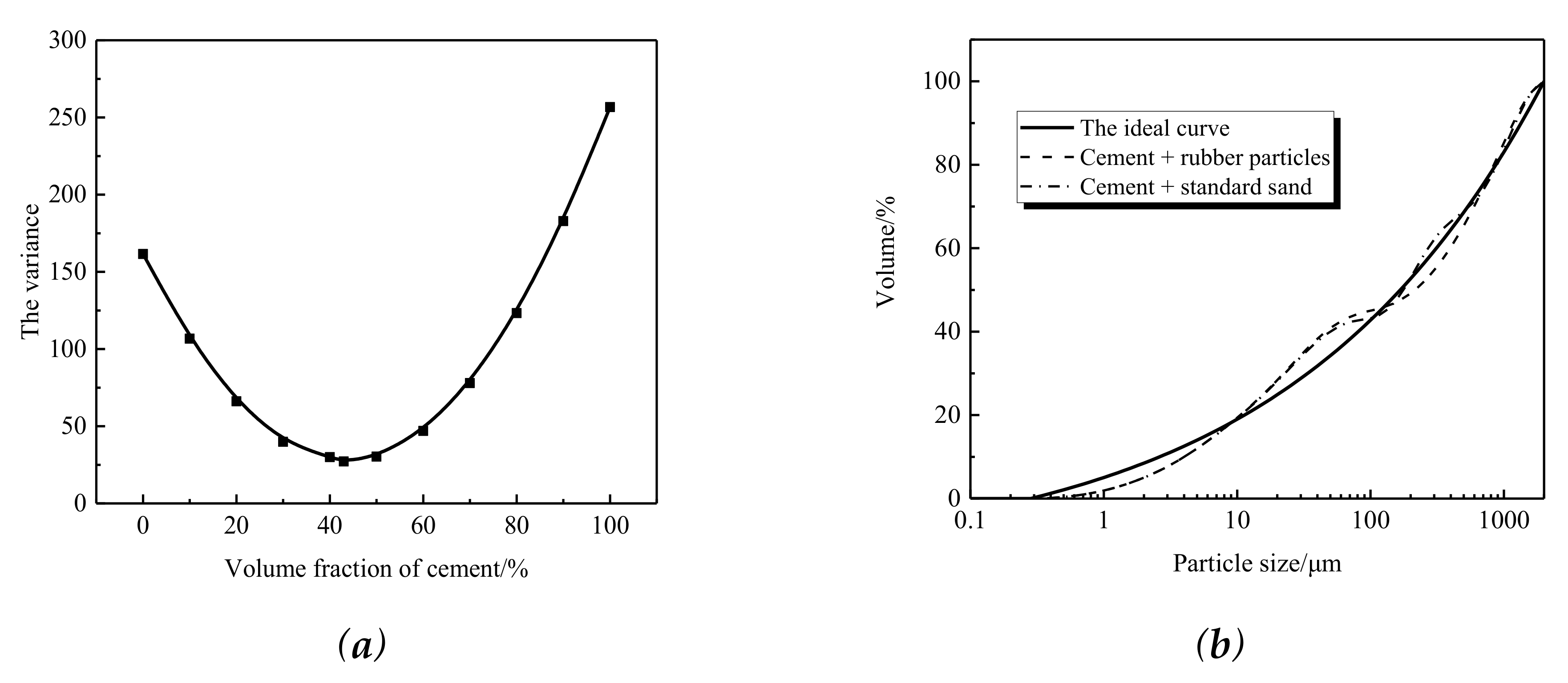
2.2.1. Mix Design
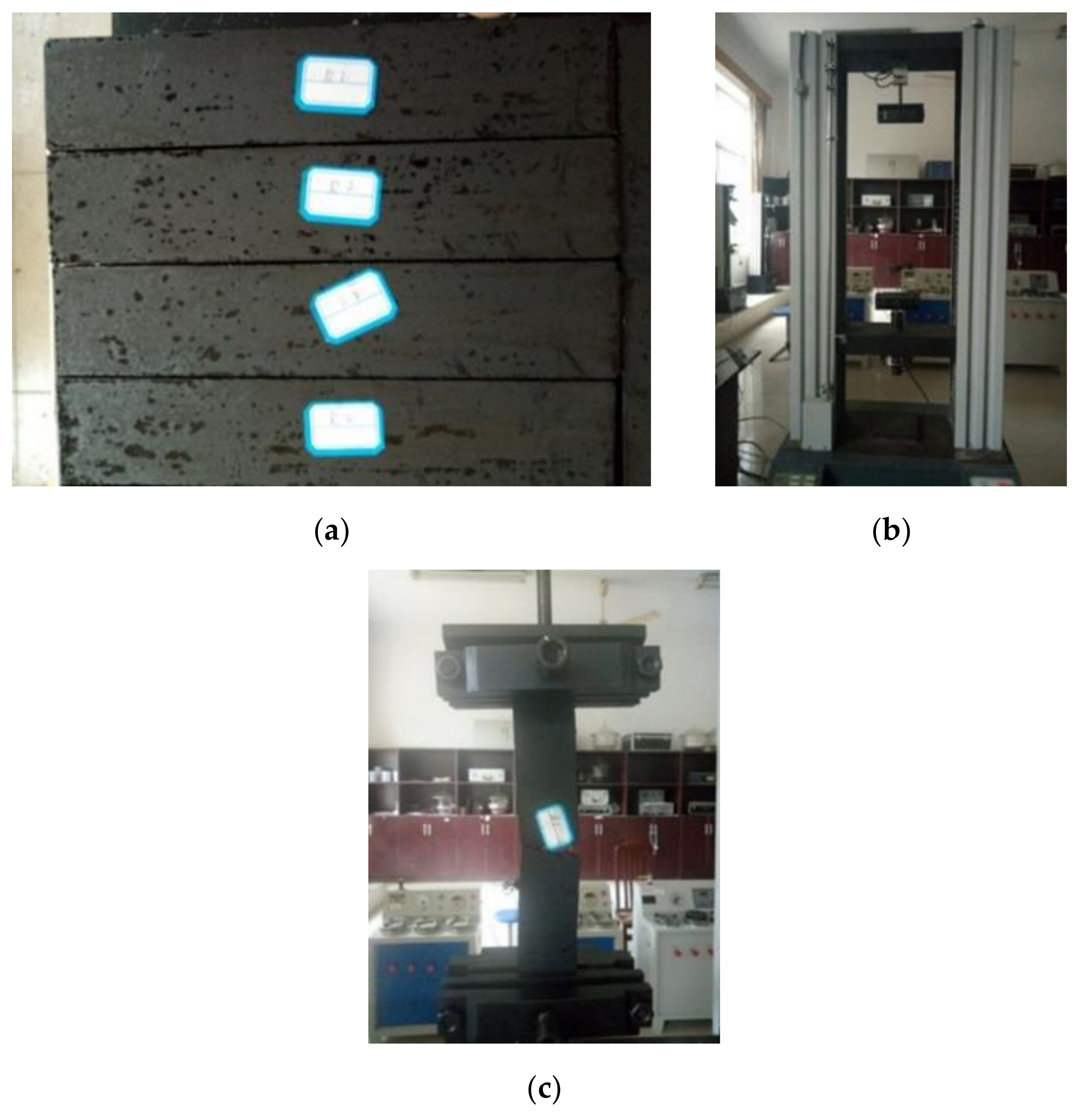
2.2.2. Specimen Preparation
2.2.3. Determination of Tensile Strength and Elongation at Break
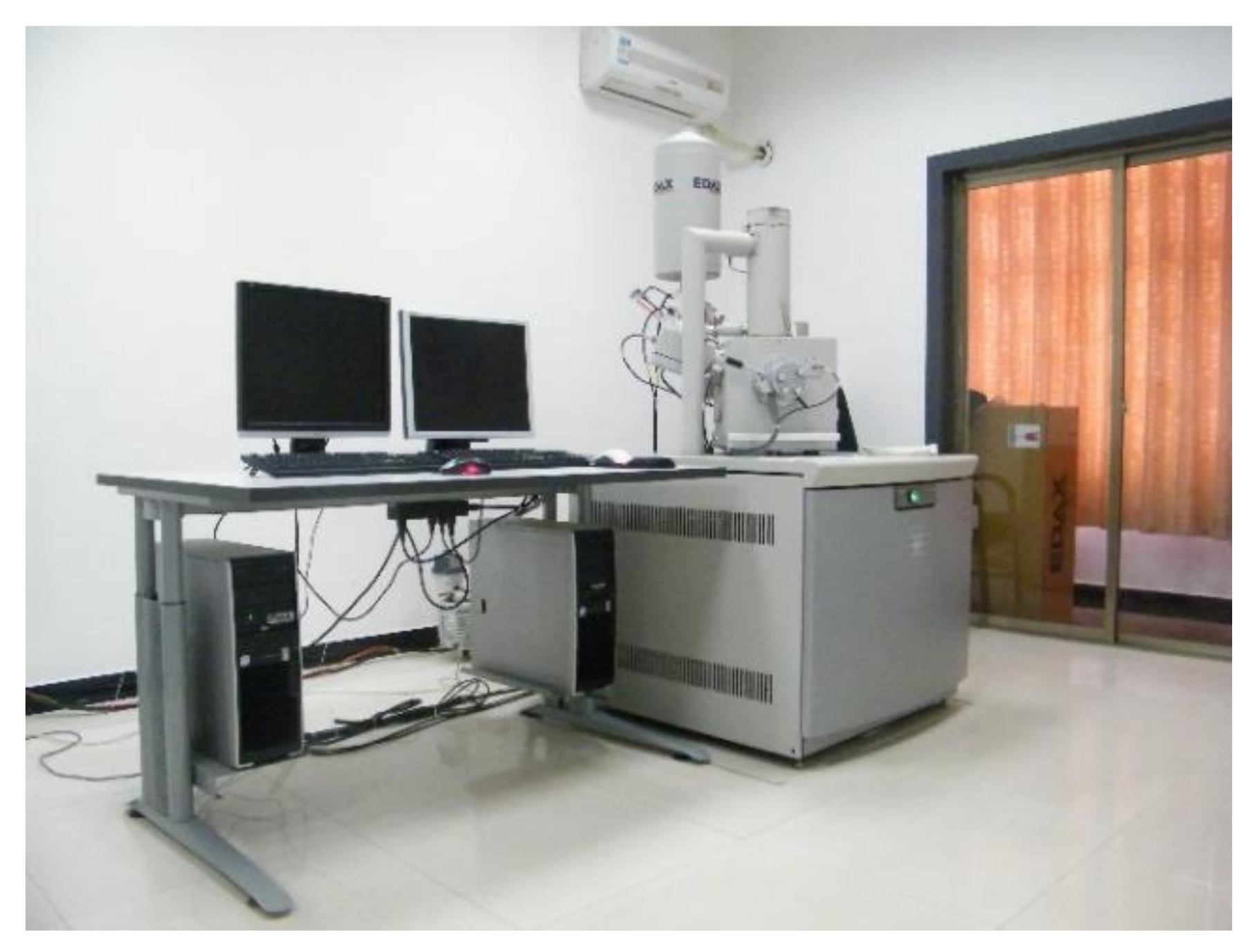
2.2.4. Microscopic Analysis
- (1)
- Instrument Introduction
- (2)
- Specimen Processing
3. Results and Discussion
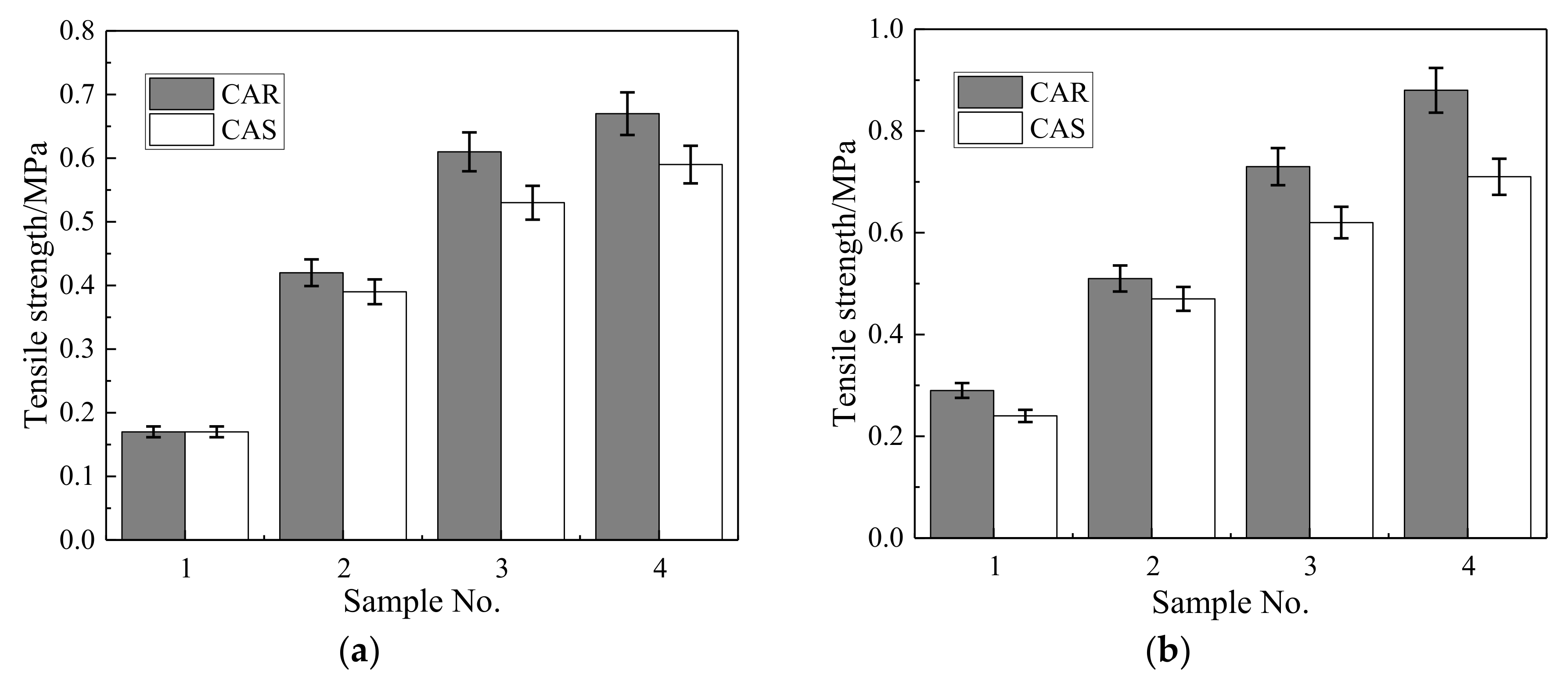
3.1. Tensile Strength
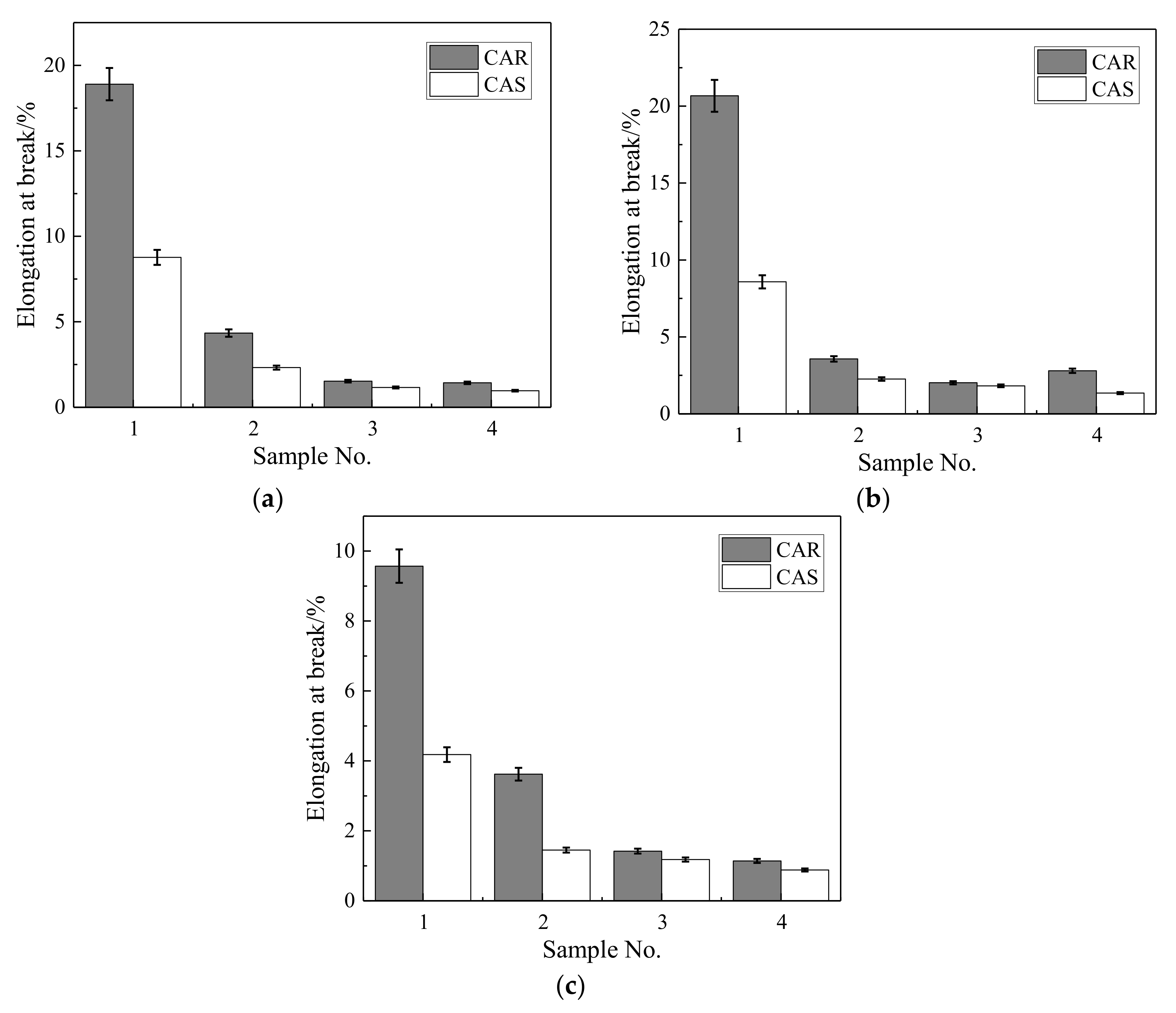
3.2. Elongation at Break
3.3. Microscopic Analysis
4. Conclusions
- The tensile strength of the CAR mortar is 9.09% higher than that of the CAS mortar at 7 days and further grows to 17.76% higher at 28 days. The elongation at break can be increased by more than 70%. The CAR system has excellent tensile properties.
- In the CAR mortar, asphalt wraps both cement hydration products and rubber particles, forming a dense and strong ITZ, which improves the tensile strength and elongation at break of the CAR mortar.
- The ternary system of cement, emulsified asphalt, and rubber particles has the potential to provide a reasonable disposal method for waste rubber.
Author Contributions
Funding
Acknowledgments
Conflicts of Interest
References
- Martínez-Barrera, G.; del Coz-Díaz, J.J.; Álvarez-Rabanal, F.P.; López Gayarre, F.; Martínez-López, M.; Cruz-Olivares, J. Waste tire rubber particles modified by gamma radiation and their use as modifiers of concrete. Case Stud. Constr. Mater. 2020, 12, e00321. [Google Scholar] [CrossRef]
- Huang, P.; Lu, W.; Zhang, F.; Wei, X. Research on performance and technology of the rubber powder modified asphalt mixture. Chin. J. Highw. Transp. 2001, 14, 4–7. [Google Scholar]
- Fontes, L.P.T.L.; Trichês, G.; Pais, J.C.; Pereira, P.A.A. Evaluating permanent deformation in asphalt rubber mixtures. Constr. Build. Mater. 2010, 24, 1193–1200. [Google Scholar] [CrossRef]
- Navarro, F.M.; Gamez, M.C.R. Influence of crumb rubber on the indirect tensile strength and stiffness modulus of hot bituminous mixes. J. Mater. Civ. Eng. 2012, 24, 715–724. [Google Scholar] [CrossRef]
- Ding, X.; Ma, T.; Zhang, W.; Zhang, D. Experimental study of stable crumb rubber asphalt and asphalt mixture. Constr. Build. Mater. 2017, 157, 975–981. [Google Scholar] [CrossRef]
- Ma, T.; Wang, H.; He, L.; Zhao, Y.; Huang, X.; Chen, J. Property Characterization of Asphalt Binders and Mixtures Modified by Different Crumb Rubbers. J. Mater. Civ. Eng. 2017, 29, 04017036. [Google Scholar] [CrossRef]
- Ding, X.; Chen, L.; Ma, T.; Ma, H.; Gu, L.; Chen, T.; Ma, Y. Laboratory investigation of the recycled asphalt concrete with stable crumb rubber asphalt binder. Constr. Build. Mater. 2019, 203, 552–557. [Google Scholar] [CrossRef]
- Youssf, O.; Hassanli, R.; Mills, J.E. Mechanical performance of FRP-confined and unconfined crumb rubber concrete containing high rubber content. J. Build. Eng. 2017, 11, 115–126. [Google Scholar] [CrossRef]
- Li, D.; Zhuge, Y.; Gravina, R.; Mills, J.E. Compressive stress strain behavior of crumb rubber concrete (CRC) and application in reinforced CRC slab. Constr. Build. Mater. 2018, 166, 745–759. [Google Scholar] [CrossRef]
- Al-Tayeb, M.M.; Abu Bakar, B.H.; Akil, H.M.; Ismail, H. Performance of rubberized and hybrid rubberized concrete structures under static and impact load conditions. Exp. Mech. 2012, 53, 377–384. [Google Scholar] [CrossRef]
- Sukontasukkul, P. Use of crumb rubber to improve thermal and sound properties of pre-cast concrete panel. Constr. Build. Mater. 2009, 23, 1084–1092. [Google Scholar] [CrossRef]
- Aslani, F. Mechanical properties of waste tire rubber concrete. J. Mater. Civ. Eng. 2016, 28, 04015152. [Google Scholar] [CrossRef]
- Li, Y.; Zhang, X.; Wang, R.; Lei, Y. Performance enhancement of rubberised concrete via surface modification of rubber: A review. Constr. Build. Mater. 2019, 227, 116691. [Google Scholar] [CrossRef]
- Li, Z.; Li, F.; Li, J.S.L. Properties of concrete incorporating rubber tyre particles. Mag. Concr. Res. 1998, 50, 297–304. [Google Scholar] [CrossRef]
- Ossola, G.; Wojcik, A. UV modification of tire rubber for use in cementitious composites. Cem. Concr. Compos. 2014, 52, 34–41. [Google Scholar] [CrossRef]
- Xie, Y.J.; Zeng, X.H.; Deng, D.H.; Liu, B.; Zheng, K.R. Mechanical characteristics of China Railway Track System(CRTS)I type slab tracks CA mortar under different strain rates. J. Build. Mater. 2010, 13, 483–486 + 528. [Google Scholar]
- Fu, Q.; Xie, Y.; Zheng, K.; Song, H.; Zhou, X. Influence of asphalt on mechanical properties of cement and asphalt mortar. J. Chin. Ceram. Soc. 2014, 42, 642. [Google Scholar]
- Song, H.; Xie, Y.; Long, G. Advances in cement emulsified asphalt mortar. Mater. Review. 2018, 32, 836–846. [Google Scholar]
- Deng, D.H.; Tian, Q.; Liu, Z.Q.; Ai, Y.Q.; Yuan, Q. Physical structure of hardened cement asphalt paste for the slab track of high-speed railway. Sci. Sin. Tech. 2014, 44, 661–671. (In Chinese) [Google Scholar]
- Ye, Q. Study on Setting and Hardening Mechanism and Microstructure of Cement Emulsified Asp Halt Concrete. Master’s Thesis, Chang’an University, Xi’an, China, 2012. [Google Scholar]


| Compositions | CaO | SiO2 | Al2O3 | Fe2O3 | SO3 | MgO |
|---|---|---|---|---|---|---|
| Mass fraction/% | 62.21 | 19.12 | 5.39 | 3.79 | 3.06 | 0.86 |
| Compositions | Ash | Acetone Extract | Carbon Black | Rubber Hydrocarbon |
|---|---|---|---|---|
| Mass fraction/% | 5.38 | 10.16 | 28.78 | 54.45 |
| Groups | Sample No. | Emulsified Asphalt | Rubber Particles | Standard Sand | Cement |
|---|---|---|---|---|---|
| 1 | R-1 | 1 | 0.15 | 0.35 | |
| S-1 | 1 | 0.41 | 0.35 | ||
| 2 | R-2 | 1 | 0.2 | 0.47 | |
| S-2 | 1 | 0.55 | 0.47 | ||
| 3 | R-3 | 1 | 0.25 | 0.58 | |
| S-3 | 1 | 0.69 | 0.58 | ||
| 4 | R-4 | 1 | 0.3 | 0.7 | |
| S-4 | 1 | 0.82 | 0.7 |
| Groups | Sample No. | Tensile Strength/MPa | ||
|---|---|---|---|---|
| 3 Days | 7 Days | 28 Days | ||
| 1 | R-1 | 0.13 | 0.17 | 0.29 |
| S-1 | 0.14 | 0.17 | 0.24 | |
| 2 | R-2 | 0.16 | 0.42 | 0.51 |
| S-2 | 0.19 | 0.39 | 0.47 | |
| 3 | R-3 | 0.49 | 0.61 | 0.73 |
| S-3 | 0.47 | 0.53 | 0.62 | |
| 4 | R-4 | 0.57 | 0.67 | 0.88 |
| S-4 | 0.52 | 0.59 | 0.71 | |
| Groups | Sample No. | Elongation at Break/% | ||
|---|---|---|---|---|
| 3 Days | 7 Days | 28 Days | ||
| 1 | R-1 | 18.9 | 20.67 | 9.57 |
| S-1 | 8.77 | 8.58 | 4.18 | |
| 2 | R-2 | 4.34 | 3.57 | 3.62 |
| S-2 | 2.32 | 2.26 | 1.45 | |
| 3 | R-3 | 1.53 | 2.02 | 1.42 |
| S-3 | 1.16 | 1.82 | 1.18 | |
| 4 | R-4 | 1.43 | 2.80 | 1.14 |
| S-4 | 0.97 | 1.35 | 0.88 | |
© 2020 by the authors. Licensee MDPI, Basel, Switzerland. This article is an open access article distributed under the terms and conditions of the Creative Commons Attribution (CC BY) license (http://creativecommons.org/licenses/by/4.0/).
Share and Cite
Li, C.; Liu, Z.; Chen, J.; Yuan, Q. Comparative Research on Tensile Properties of Cement–Emulsified Asphalt–Standard Sand (CAS) Mortar and Cement–Emulsified Asphalt–Rubber Particle (CAR) Mortar. Materials 2020, 13, 4042. https://doi.org/10.3390/ma13184042
Li C, Liu Z, Chen J, Yuan Q. Comparative Research on Tensile Properties of Cement–Emulsified Asphalt–Standard Sand (CAS) Mortar and Cement–Emulsified Asphalt–Rubber Particle (CAR) Mortar. Materials. 2020; 13(18):4042. https://doi.org/10.3390/ma13184042
Chicago/Turabian StyleLi, Chaoyuan, Zanqun Liu, Juan Chen, and Qiang Yuan. 2020. "Comparative Research on Tensile Properties of Cement–Emulsified Asphalt–Standard Sand (CAS) Mortar and Cement–Emulsified Asphalt–Rubber Particle (CAR) Mortar" Materials 13, no. 18: 4042. https://doi.org/10.3390/ma13184042
APA StyleLi, C., Liu, Z., Chen, J., & Yuan, Q. (2020). Comparative Research on Tensile Properties of Cement–Emulsified Asphalt–Standard Sand (CAS) Mortar and Cement–Emulsified Asphalt–Rubber Particle (CAR) Mortar. Materials, 13(18), 4042. https://doi.org/10.3390/ma13184042