Theoretical Analysis of Blast Protection of Graded Metal Foam-Cored Sandwich Cylinders/Rings


Abstract
1. Introduction
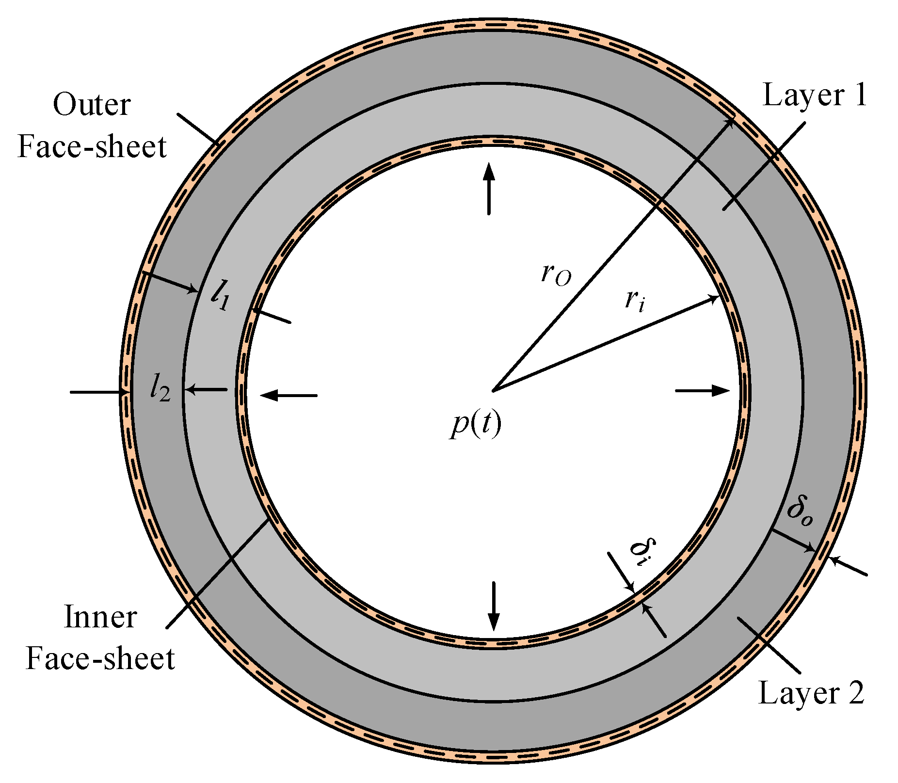
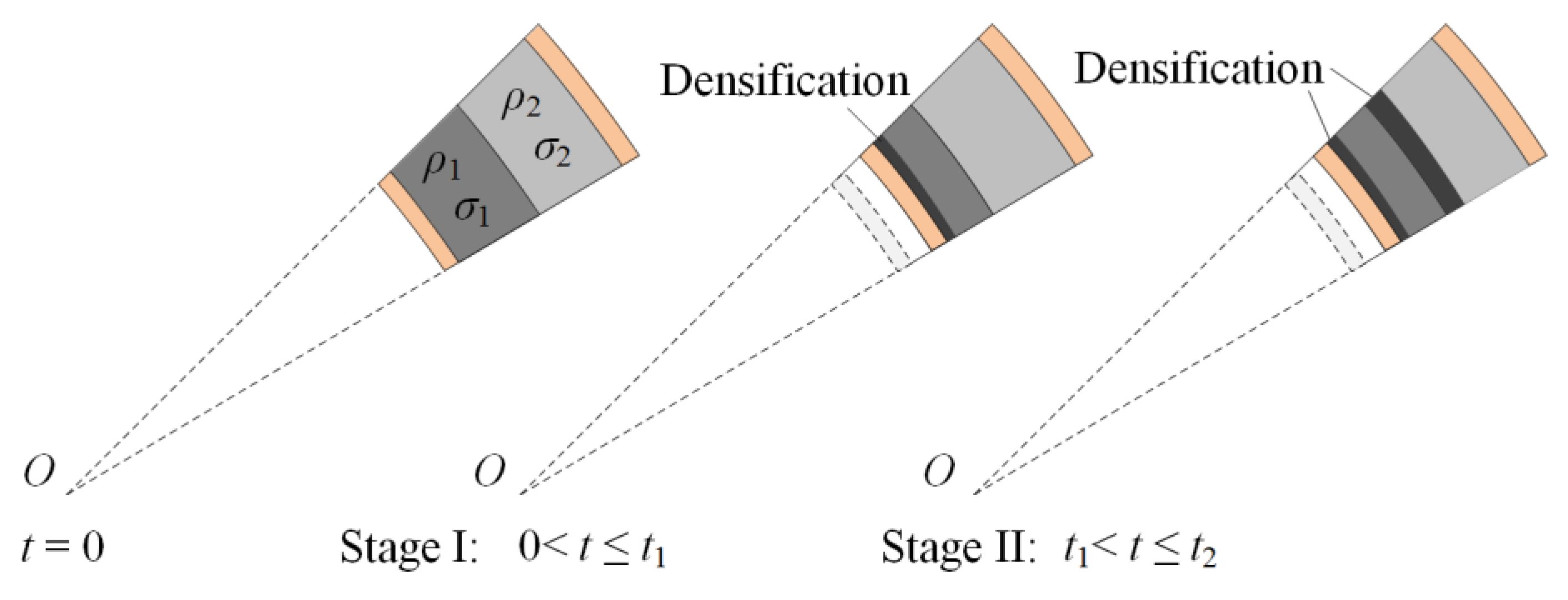
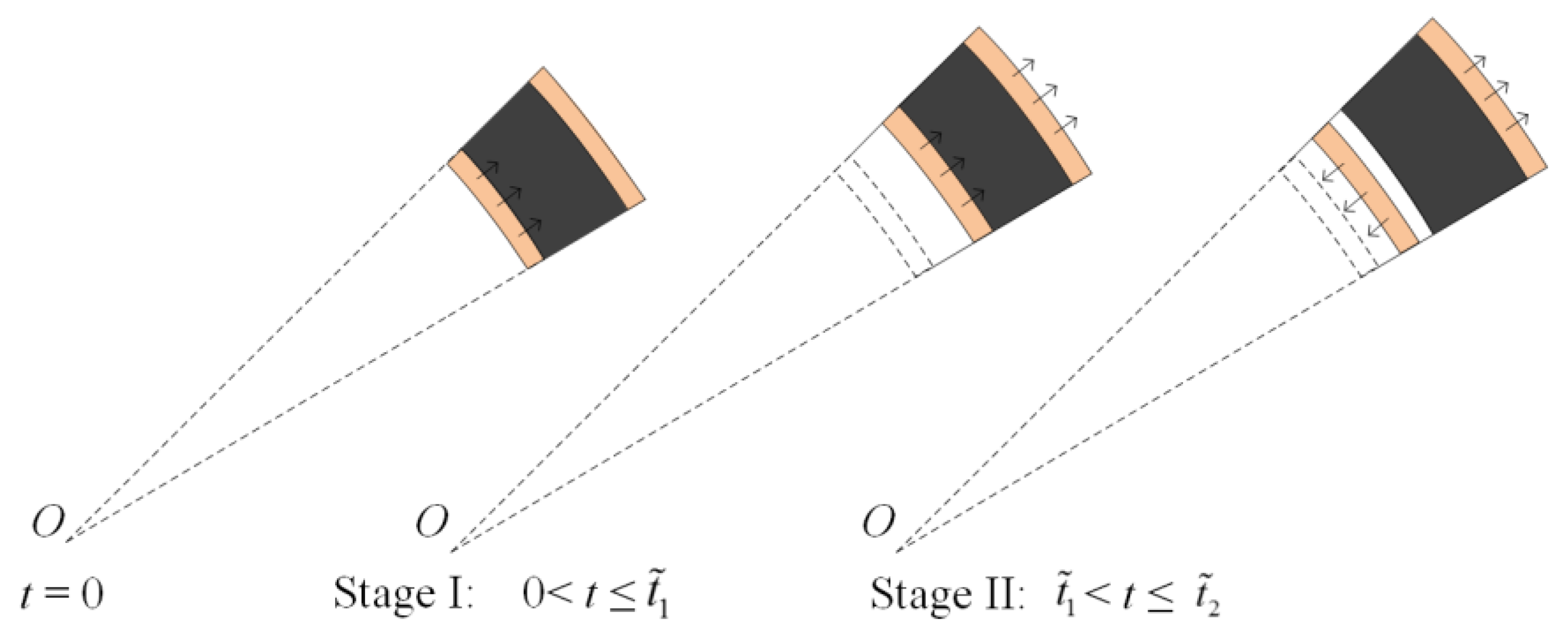
2. Analytical Model
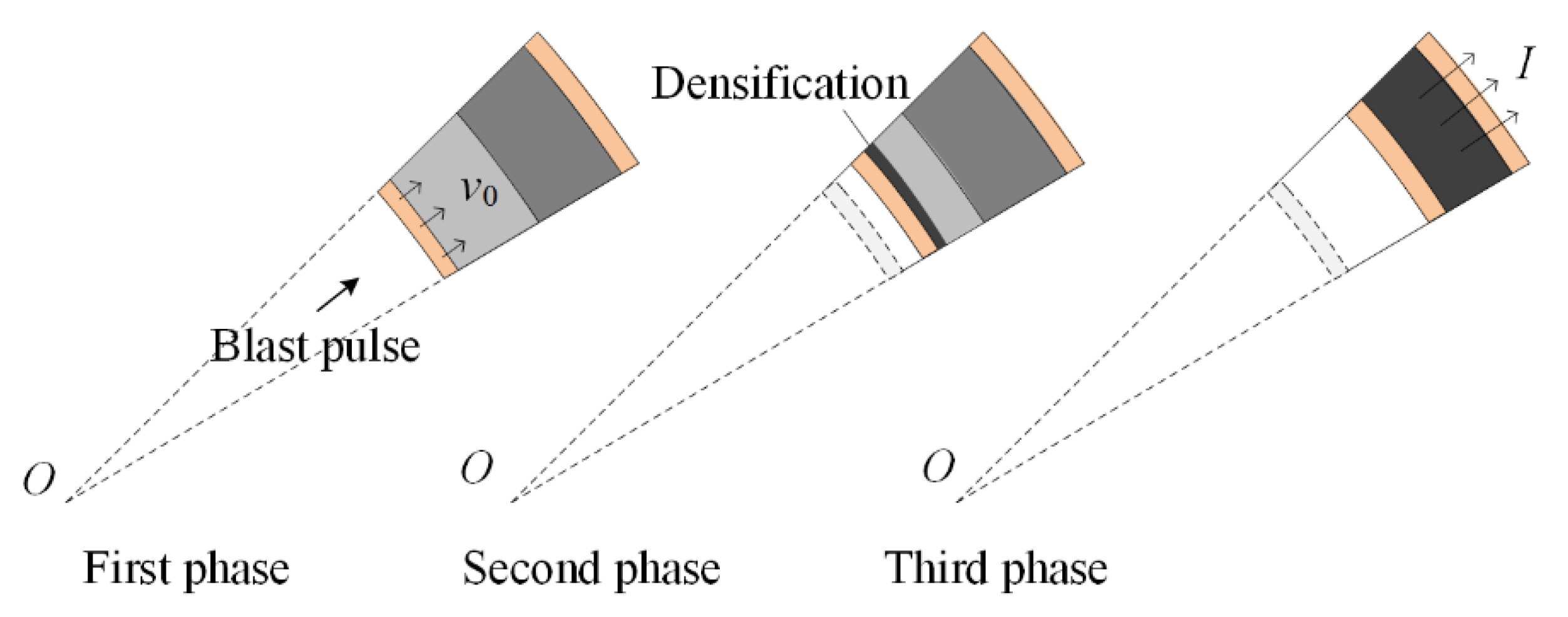
2.1. First Phase: FSI
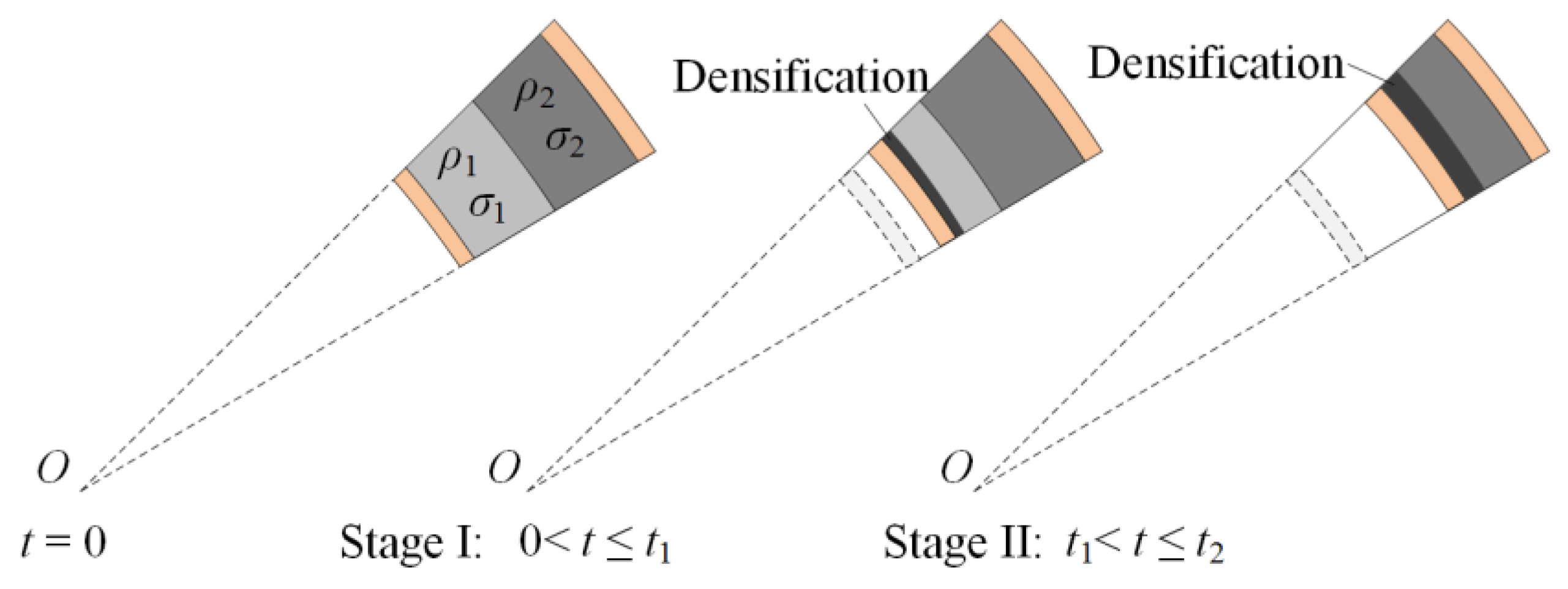
2.2. Second Phase: Core Crushing
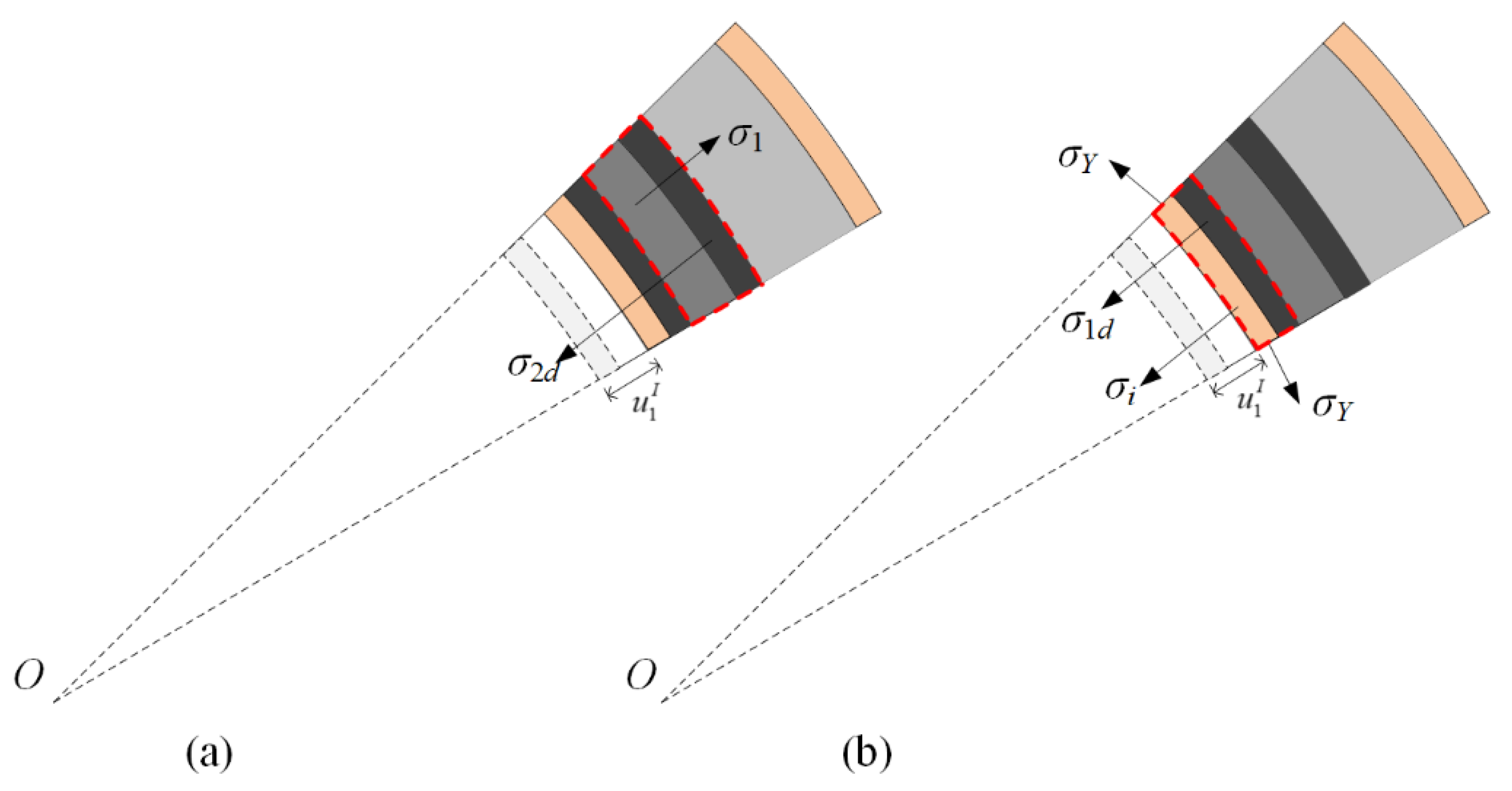
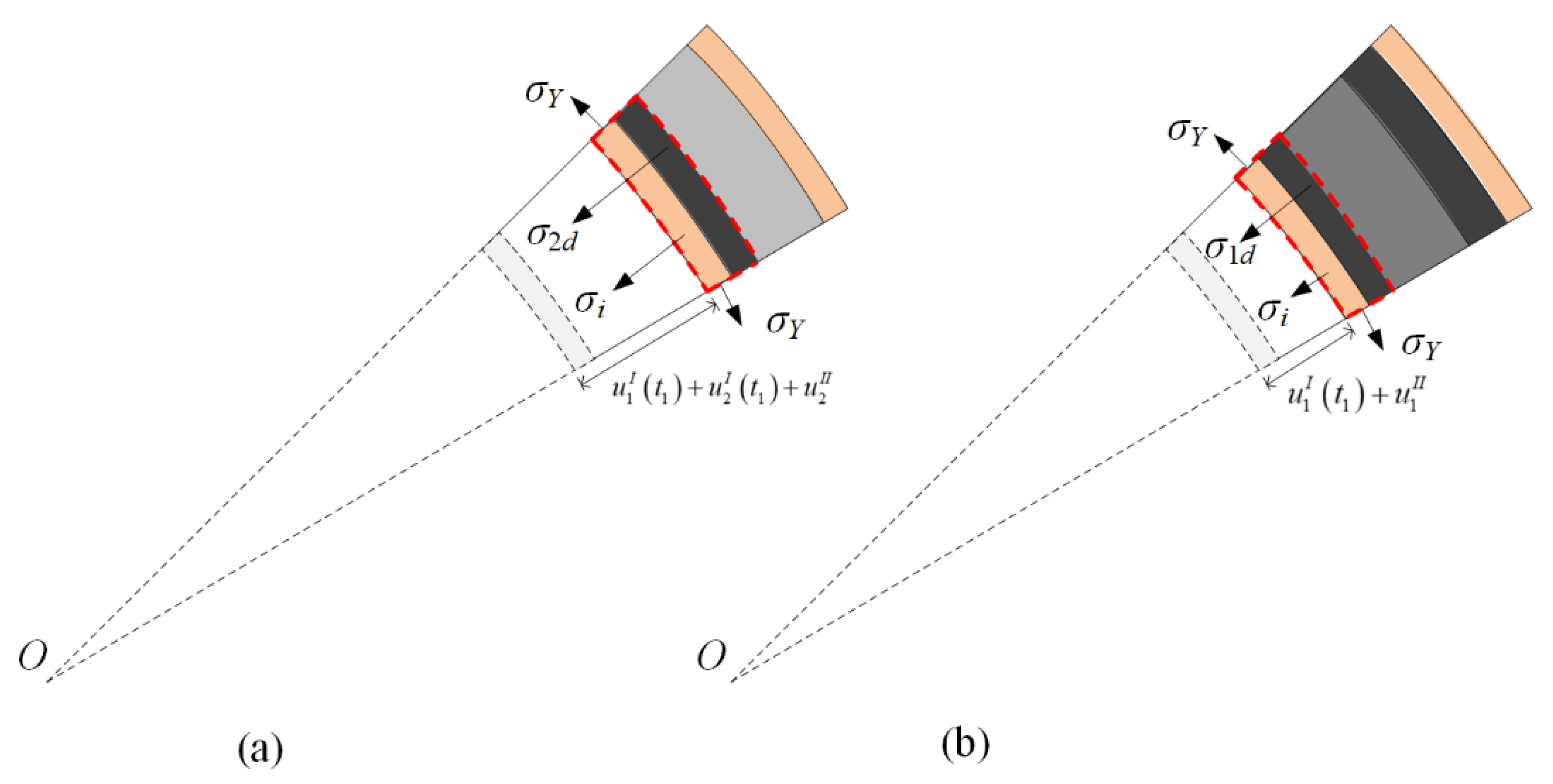
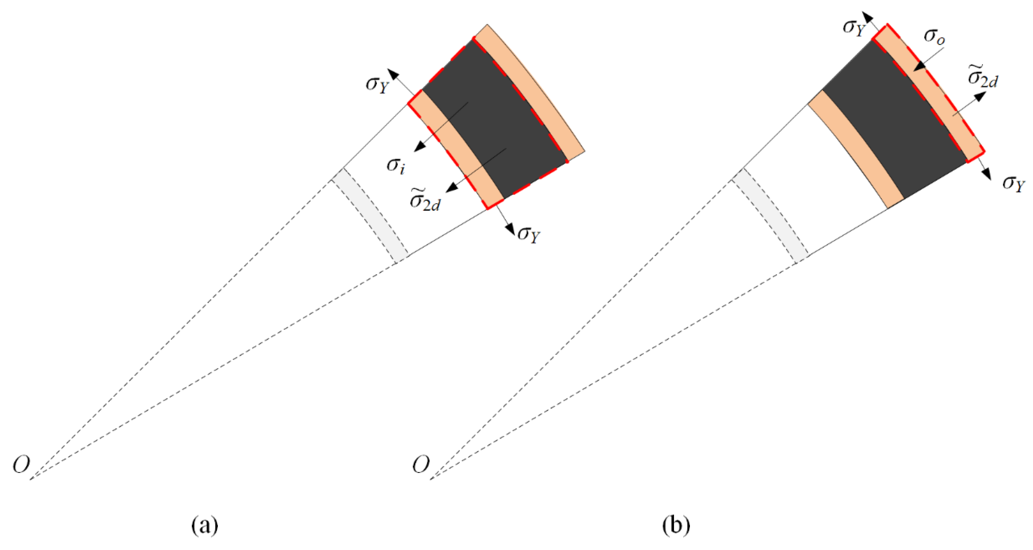
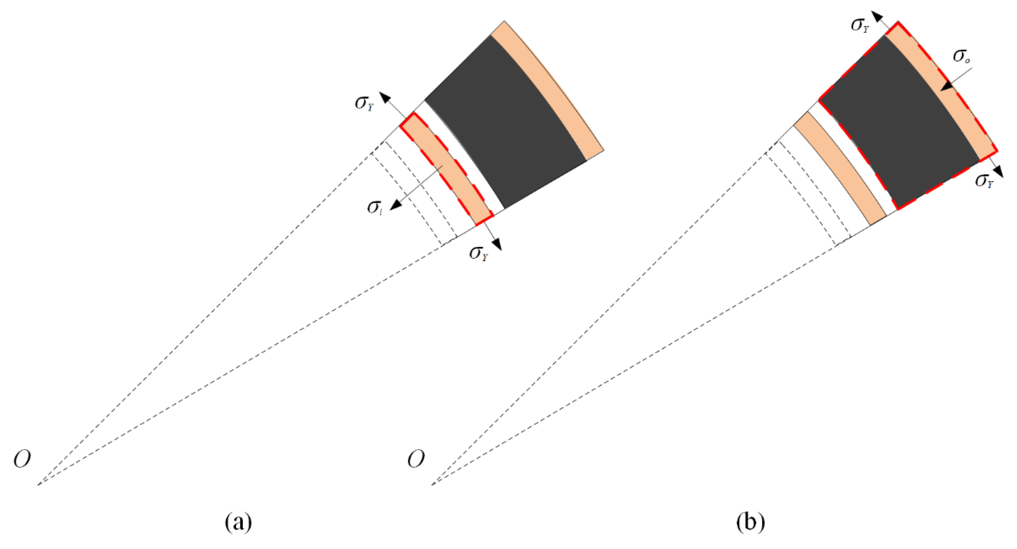
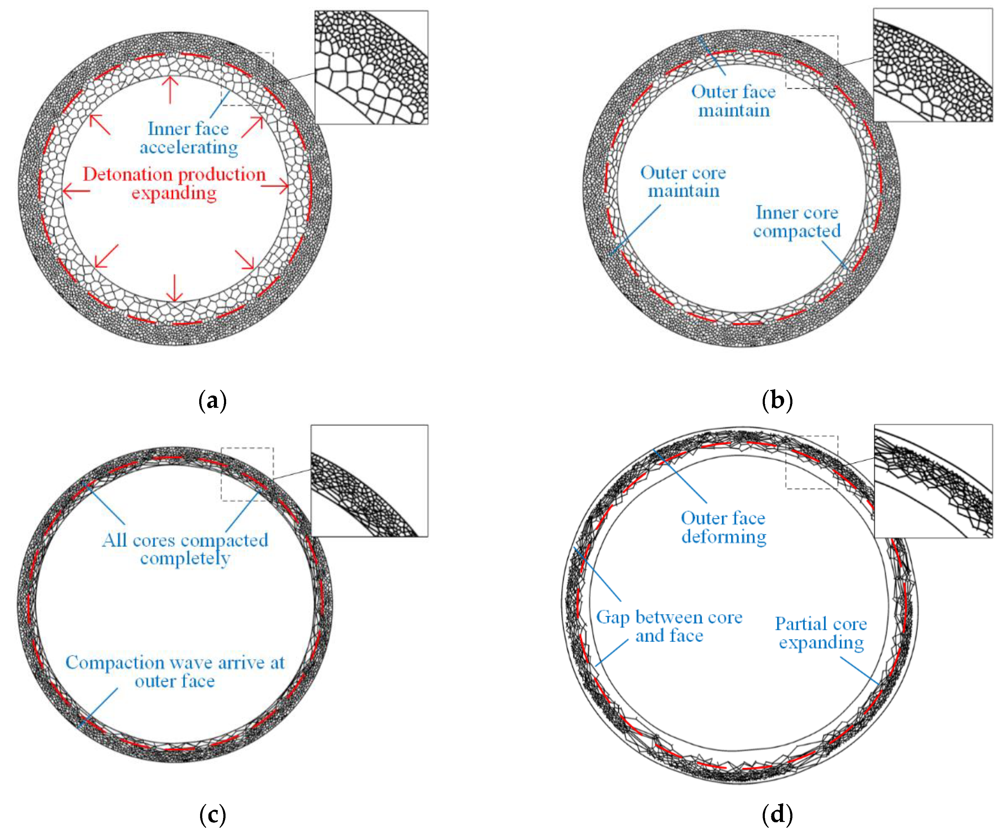
2.2.1. Positive Gradient Core Situation
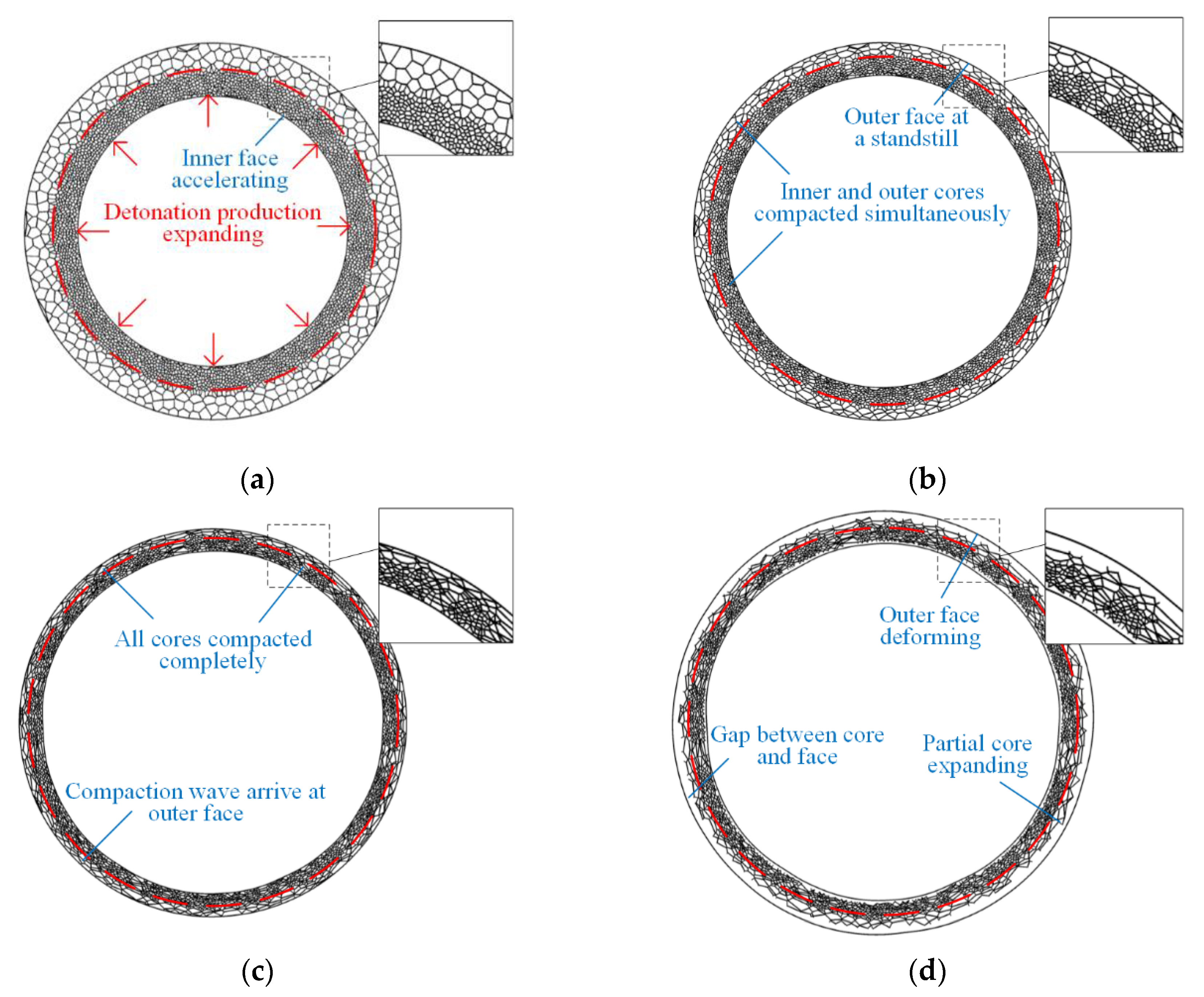
2.2.2. Negative-Gradient Core Situation
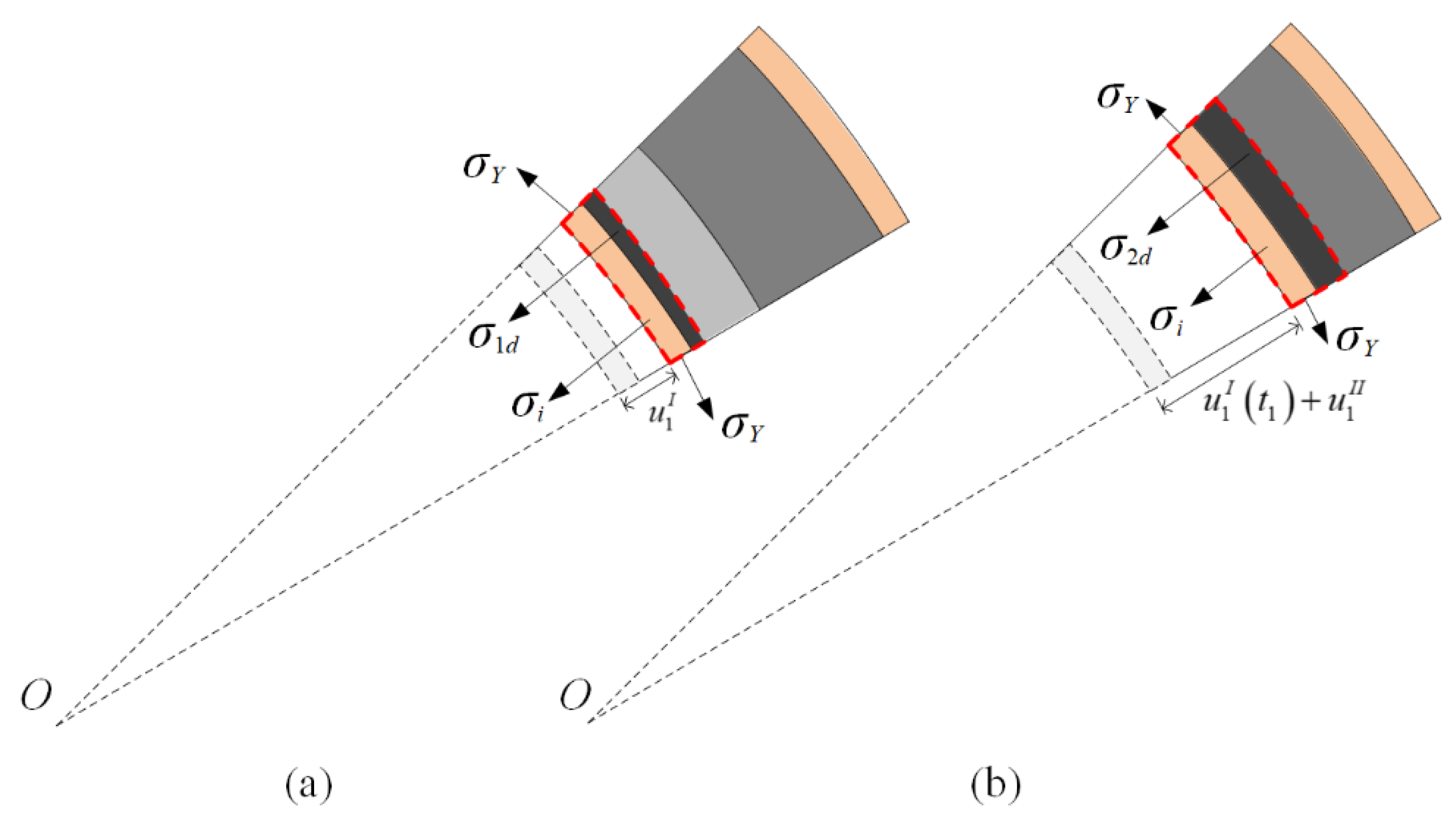
2.3. Third Phase: Outer Face-Sheet Deformation
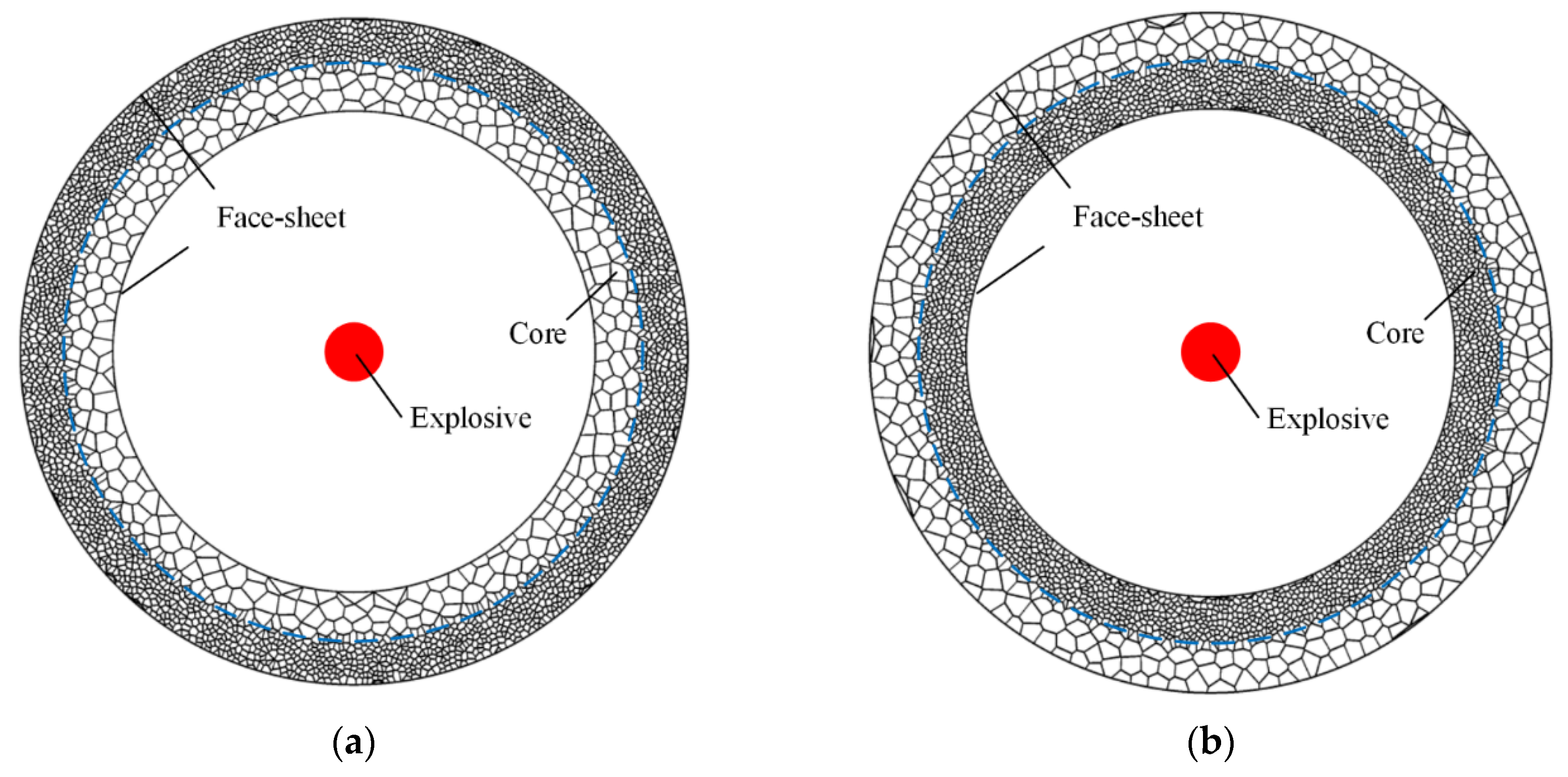
3. FE Model
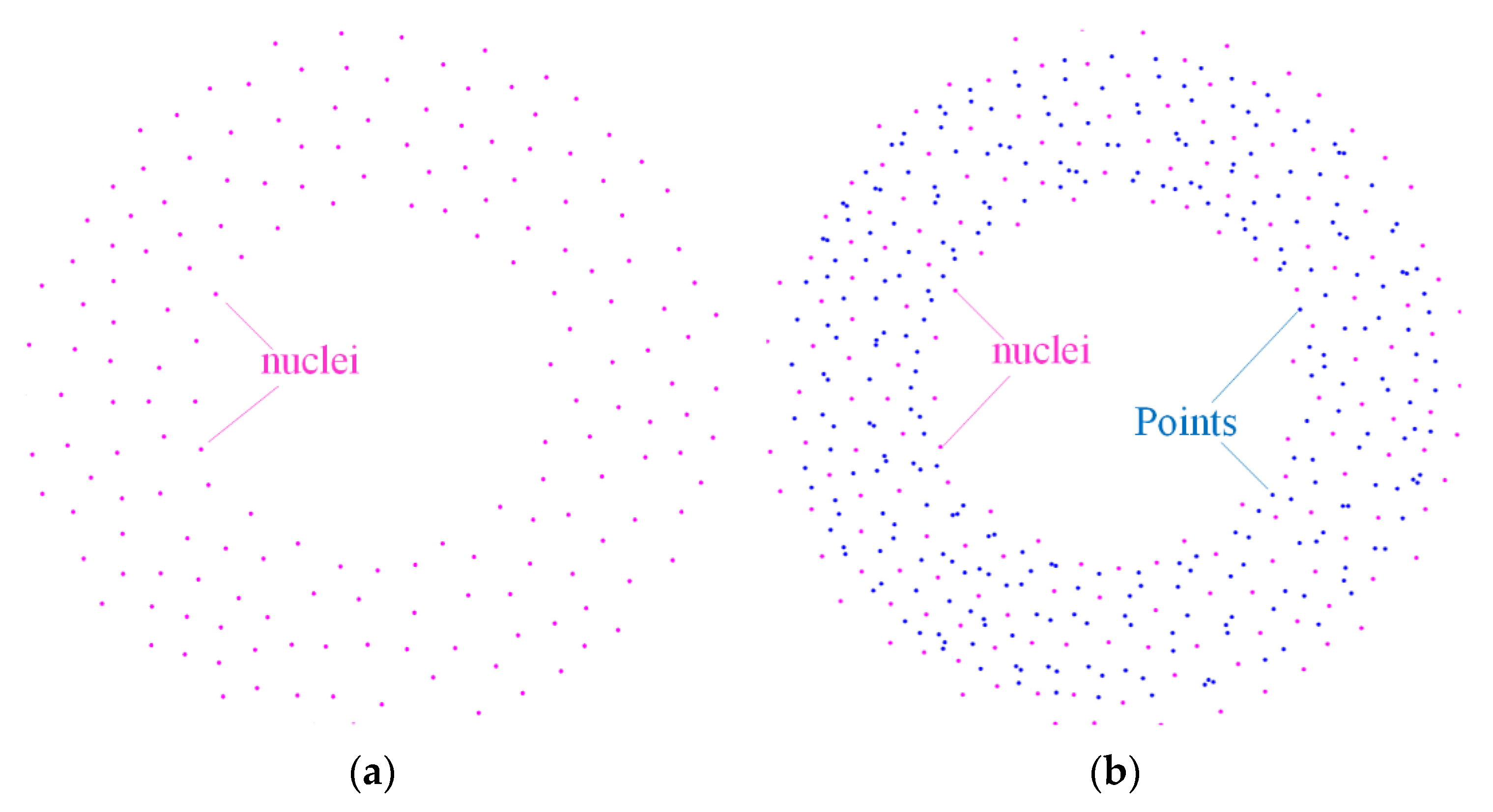
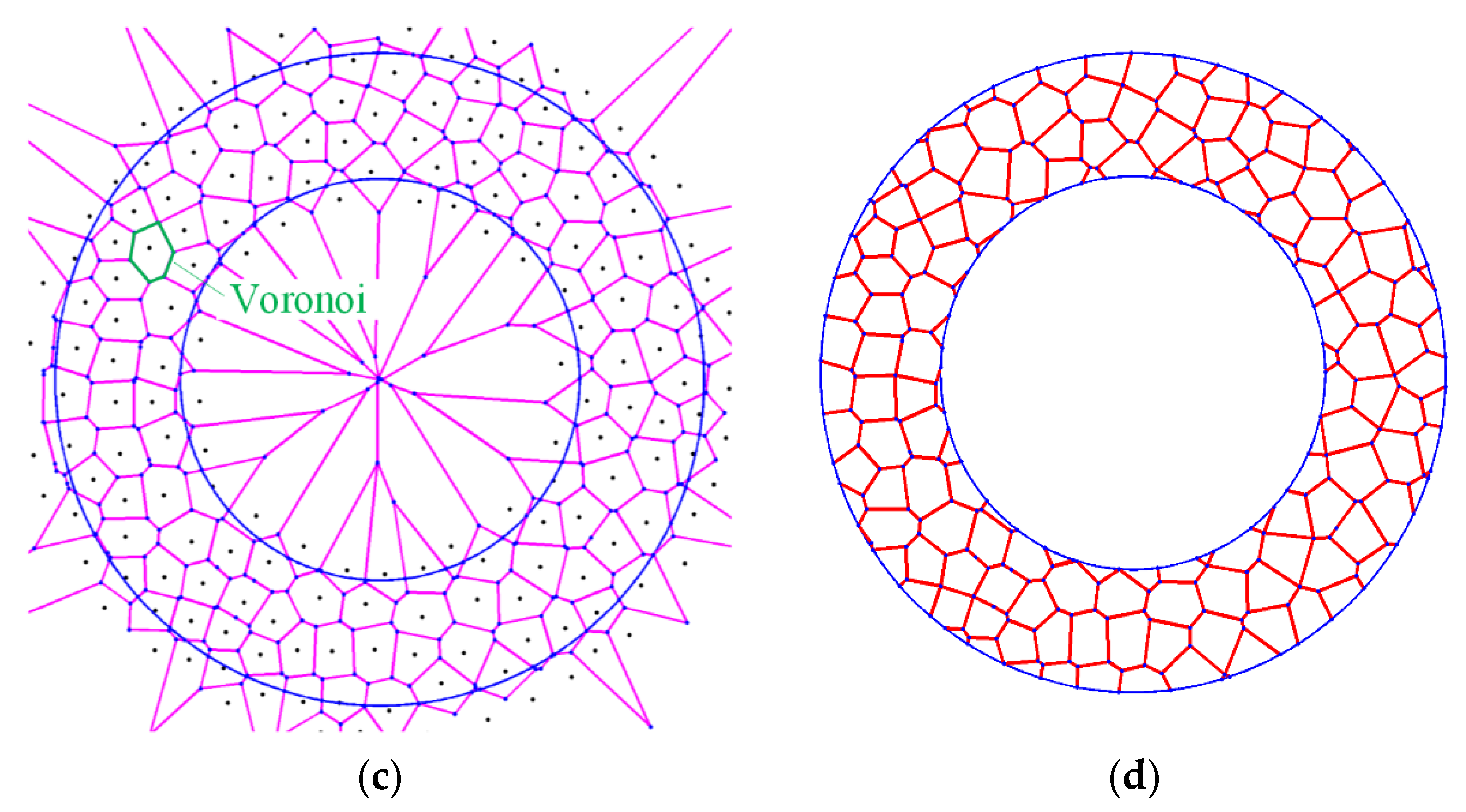
3.1. Foam Core Modeling
3.2. Material Model
3.3. Numerical Model
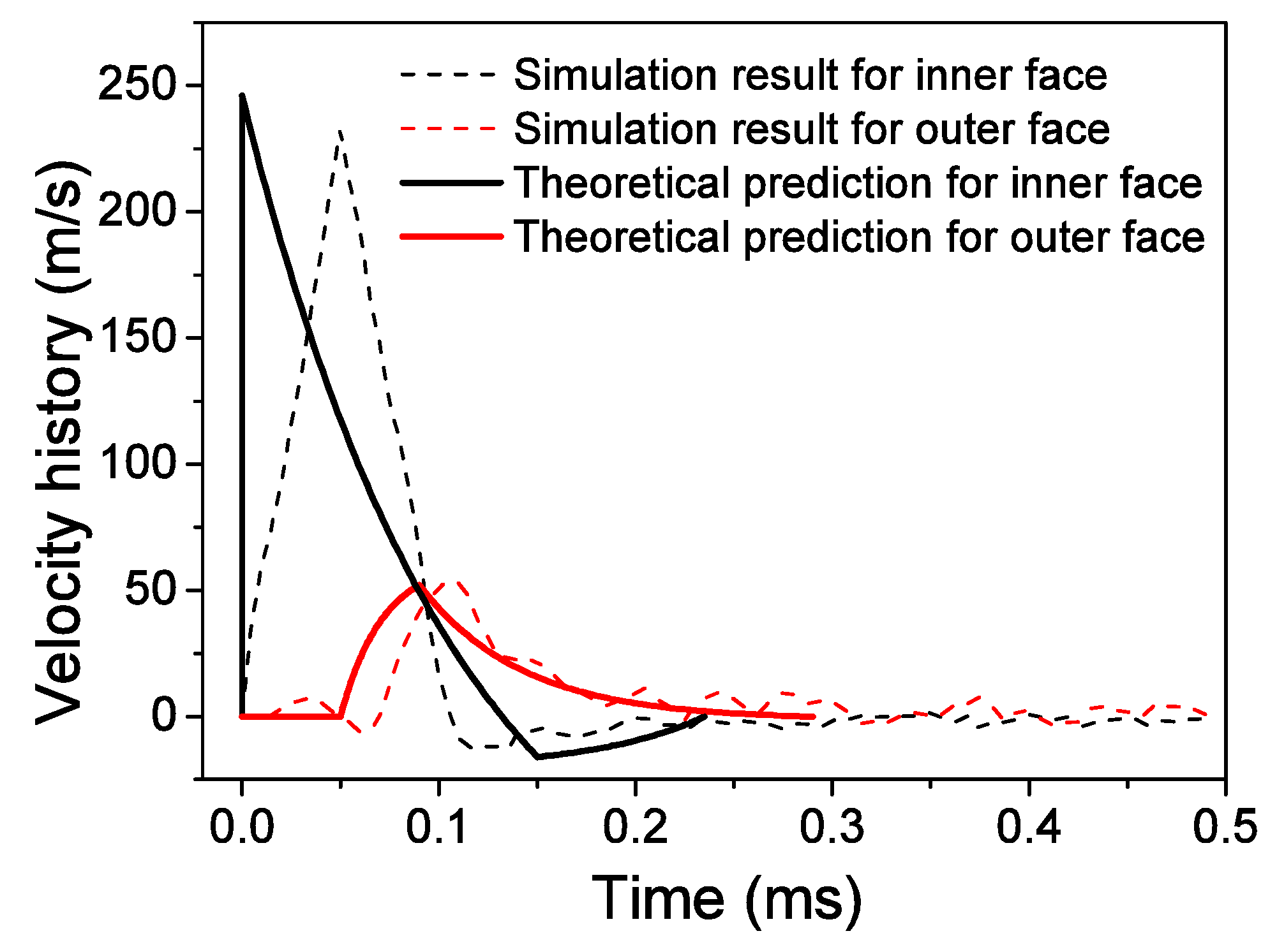
4. Comparisons of Theoretical and Numerical Results
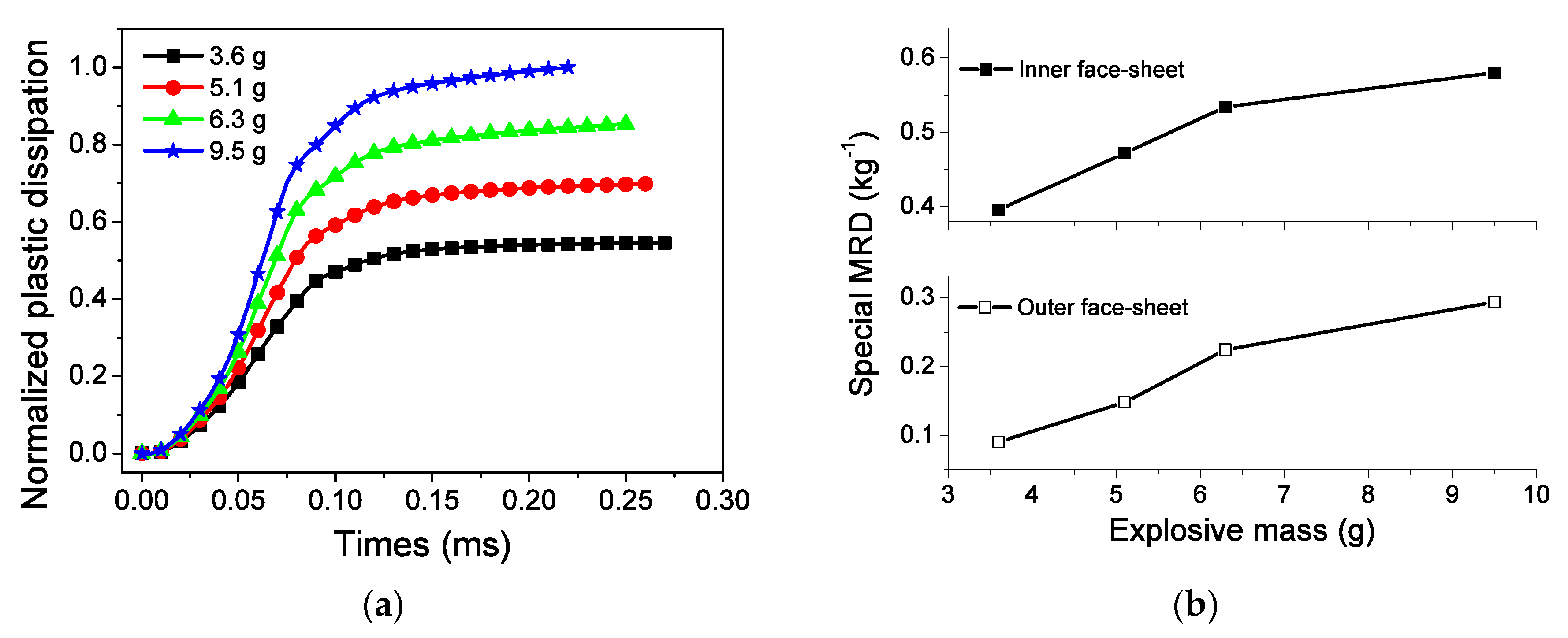
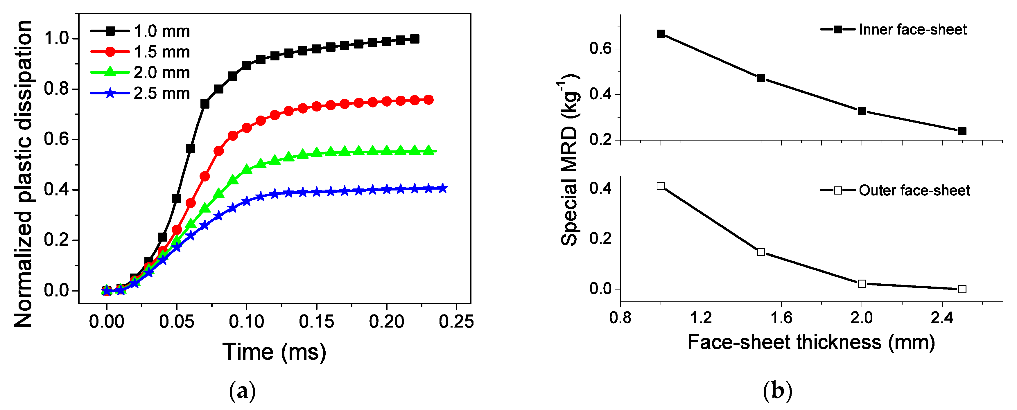
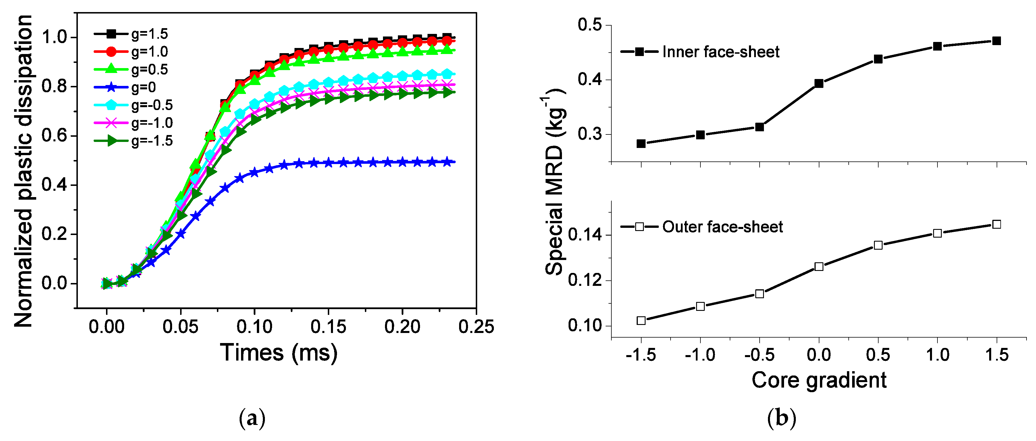
5. Discussion
6. Conclusions
Author Contributions
Funding
Conflicts of Interest
References
- Alqwasmi, N.; Tarlochan, F.; Alkhatib, S.E. Study of mild steel sandwich structure energy absorption performance subjected to localized impulsive loading. Materials 2020, 13, 670. [Google Scholar] [CrossRef] [PubMed]
- Li, S.; Li, X.; Wang, Z.; Wu, G.; Lu, G.; Zhao, L. Sandwich panels with layered graded aluminum honeycomb cores under blast loading. Compos. Struct. 2017, 173, 242–254. [Google Scholar] [CrossRef]
- Zhou, T.; Zhang, P.; Xiao, W.; Liu, J.; Cheng, Y. Experimental investigation on the performance of pvc foam core sandwich panels under air blast loading. Compos. Struct. 2019, 226, 111081. [Google Scholar] [CrossRef]
- Sun, Y.; Guo, L.-C.; Wang, T.-S.; Yao, L.-J.; Sun, X.-Y. Bending strength and failure of single-layer and double-layer sandwich structure with graded truss core. Compos. Struct. 2019, 226, 111204. [Google Scholar] [CrossRef]
- Amaro, A.M.; Neto, M.A.; Cirne, J.S.; Reis, P.N.B. Mechanical characterization of different aluminium foams at high strain rates. Materials 2019, 12, 1428. [Google Scholar] [CrossRef]
- Qu, J.; Ju, D.; Gao, S.; Chen, J. Research on the dynamic mechanical properties of polymethacrylimide foam sandwich structure. Compos. Struct. 2018, 204, 22–30. [Google Scholar] [CrossRef]
- Chen, Y.; Ye, L.; Escobedo-Diaz, J.P.; Zhang, Y.-X.; Fu, K. Quasi-static and dynamic progressive crushing of cf/ep composite sandwich panels under in-plane localised compressive loads. Compos. Struct. 2019, 222, 110839. [Google Scholar] [CrossRef]
- Sun, Y.; Li, Q.M. Dynamic compressive behaviour of cellular materials: A review of phenomenon, mechanism and modelling. Int. J. Impact Eng. 2018, 112, 74–115. [Google Scholar] [CrossRef]
- Davids, S.A.; Langdon, G.S.; Nurick, G.N. The influence of charge geometry on the response of partially confined right circular stainless steel cylinders subjected to blast loading. Int. J. Impact Eng. 2017, 108, 252–262. [Google Scholar] [CrossRef]
- Baba, B.O. Curved sandwich composites with layer-wise graded cores under impact loads. Compos. Struct. 2017, 159, 1–11. [Google Scholar] [CrossRef]
- Chang, B.; Zheng, Z.; Zhang, Y.; Zhao, K.; He, S.; Yu, J. Crashworthiness design of graded cellular materials: An asymptotic solution considering loading rate sensitivity. Int. J. Impact Eng. 2020, 143, 103611. [Google Scholar] [CrossRef]
- Jing, L.; Su, X.; Chen, D.; Yang, F.; Zhao, L. Experimental and numerical study of sandwich beams with layered-gradient foam cores under low-velocity impact. Thin-Walled Struct. 2019, 135, 227–244. [Google Scholar] [CrossRef]
- Sun, G.; Zhang, J.; Li, S.; Fang, J.; Wang, E.; Li, Q. Dynamic response of sandwich panel with hierarchical honeycomb cores subject to blast loading. Thin-Walled Struct. 2019, 142, 499–515. [Google Scholar] [CrossRef]
- Jin, X.; Wang, Z.; Ning, J.; Xiao, G.; Liu, E.; Shu, X. Dynamic response of sandwich structures with graded auxetic honeycomb cores under blast loading. Compos. Part B Eng. 2016, 106, 206–217. [Google Scholar] [CrossRef]
- Liang, M.Z.; Li, X.Y.; Lin, Y.L.; Zhang, K.F.; Lu, F.Y. Dynamic compressive behaviors of two-layer graded aluminum foams under blast loading. Materials 2019, 12, 1445. [Google Scholar] [CrossRef]
- Ding, Y.; Wang, S.; Zhao, K.; Zheng, Z.; Yang, L.; Yu, J. Blast alleviation of cellular sacrificial cladding: A nonlinear plastic shock model. Int. J. Appl. Mech. 2016, 8, 1650057. [Google Scholar] [CrossRef]
- Chen, G.; Cheng, Y.; Zhang, P.; Liu, J.; Chen, C.; Cai, S. Design and modelling of auxetic double arrowhead honeycomb core sandwich panels for performance improvement under air blast loading. J. Sandwich Struct. Mater. 2020, 1099636220935563. [Google Scholar] [CrossRef]
- Shen, C.J.; Lu, G.; Yu, T.X. Investigation into the behavior of a graded cellular rod under impact. Int. J. Impact Eng. 2014, 74, 92–106. [Google Scholar] [CrossRef]
- Liu, J.; Hou, B.; Lu, F.; Zhao, H. A theoretical study of shock front propagation in the density graded cellular rods. Int. J. Impact Eng. 2015, 80, 133–142. [Google Scholar] [CrossRef]
- Zhang, J.; Wang, Z.; Zhao, L. Dynamic response of functionally graded cellular materials based on the voronoi model. Compos. Part B Eng. 2016, 85, 176–187. [Google Scholar] [CrossRef]
- Liang, M.; Lu, F.; Zhang, G.; Li, X. Design of stepwise foam claddings subjected to air-blast based on voronoi model. Steel Compos. Struct. 2017, 23, 107–114. [Google Scholar] [CrossRef]
- Liang, M.; Li, Z.; Lu, F.; Li, X. Theoretical and numerical investigation of blast responses of continuous-density graded cellular materials. Compos. Struct. 2017, 164, 170–179. [Google Scholar] [CrossRef]
- Eloy, F.D.S.; Gomes, G.F.; Ancelotti, J.A.C.; da Cunha, J.S.S.; Faria Bombard, A.J.; Junqueira, D.M. Experimental dynamic analysis of composite sandwich beams with magnetorheological honeycomb core. Eng. Struct. 2018, 176, 231–242. [Google Scholar] [CrossRef]
- Birman, V.; Kardomateas, G.A. Review of current trends in research and applications of sandwich structures. Compos. Part B Eng. 2018, 142, 221–240. [Google Scholar] [CrossRef]
- Liu, X.; Tian, X.; Lu, T.J.; Zhou, D.; Liang, B. Blast resistance of sandwich-walled hollow cylinders with graded metallic foam cores. Compos. Struct. 2012, 94, 2485–2493. [Google Scholar] [CrossRef]
- Zhu, W.; Huang, G.-Y.; Liu, C.-M.; Feng, S.-S. Experimental and numerical investigation of a hollow cylindrical water barrier against internal blast loading. Eng. Struct. 2018, 172, 789–806. [Google Scholar] [CrossRef]
- Shen, J.; Lu, G.; Zhao, L.; Zhang, Q. Short sandwich tubes subjected to internal explosive loading. Eng. Struct. 2013, 55, 56–65. [Google Scholar] [CrossRef]
- Karagiozova, D.; Langdon, G.S.; Nurick, G.N.; Niven, T. The influence of a low density foam sandwich core on the response of a partially confined steel cylinder to internal air-blast. Int. J. Impact Eng. 2016, 92, 32–49. [Google Scholar] [CrossRef]
- Liang, M.; Lu, F.; Zhang, G.; Li, X. Experimental and numerical study of aluminum foam-cored sandwich tubes subjected to internal air blast. Compos. Part B Eng. 2017, 125, 134–143. [Google Scholar] [CrossRef]
- Liang, M.; Zhang, G.; Lu, F.; Li, X. Blast resistance and design of sandwich cylinder with graded foam cores based on the voronoi algorithm. Thin-Walled Struct. 2017, 112, 98–106. [Google Scholar] [CrossRef]
- Liang, M.Z.; Li, X.Y.; Lin, Y.L.; Lu, F.Y. Compaction wave propagation in layered cellular materials under air-blast. Int. J. Appl. Mech. 2019, 11, 1950003. [Google Scholar] [CrossRef]
- Reid, S.R.; Peng, C. Dynamic uniaxial crushing of wood. Int. J. Impact Eng. 1997, 19, 531–570. [Google Scholar] [CrossRef]
- Tan, P.J.; Reid, S.R.; Harrigan, J.J.; Zou, Z.; Li, S. Dynamic compressive strength properties of aluminium foams. Part II—‘shock’ theory and comparison with experimental data and numerical models. J. Mech. Phys. Solids 2005, 53, 2206–2230. [Google Scholar] [CrossRef]
- Jing, L.; Zhao, L.M. Blast resistance and energy absorption of sandwich panels with layered gradient metallic foam cores. J. Sandw. Struct. Mater. 2019, 21, 464–482. [Google Scholar] [CrossRef]
- Liang, M.; Li, X.; Lin, Y.; Zhang, K.; Lu, F. Influence of multi-layer core on the blast response of composite sandwich cylinders. Int. J. Appl. Mech. 2020, 12, 2050018. [Google Scholar] [CrossRef]
- Zheng, Z.; Wang, C.; Yu, J.; Reid, S.R.; Harrigan, J.J. Dynamic stress-strain states for metal foams using a 3d cellular model. J. Mech. Phys. Solids 2014, 72, 93–114. [Google Scholar] [CrossRef]
- Shen, C.J.; Yu, T.X.; Lu, G. Double shock mode in graded cellular rod under impact. Int. J. Solids Struct. 2013, 50, 217–233. [Google Scholar] [CrossRef]


| Explosive | A | B | ω | R1 | R2 | Em0 (J/m3) |
|---|---|---|---|---|---|---|
| TNT | 3.74 | 0.032 | 0.3 | 4.15 | 0.95 | 70 |
| Material | Density ρs (kg/m3) | Young Modulus Es (GPa) | Poisson Ratio γs | Yield Stress σys (MPa) |
|---|---|---|---|---|
| Aluminum | 2730 | 69.2 | 0.3 | 168 |
© 2020 by the authors. Licensee MDPI, Basel, Switzerland. This article is an open access article distributed under the terms and conditions of the Creative Commons Attribution (CC BY) license (http://creativecommons.org/licenses/by/4.0/).
Share and Cite
Liang, M.; Li, X.; Lin, Y.; Zhang, K.; Lu, F. Theoretical Analysis of Blast Protection of Graded Metal Foam-Cored Sandwich Cylinders/Rings. Materials 2020, 13, 3903. https://doi.org/10.3390/ma13173903
Liang M, Li X, Lin Y, Zhang K, Lu F. Theoretical Analysis of Blast Protection of Graded Metal Foam-Cored Sandwich Cylinders/Rings. Materials. 2020; 13(17):3903. https://doi.org/10.3390/ma13173903
Chicago/Turabian StyleLiang, Minzu, Xiangyu Li, Yuliang Lin, Kefan Zhang, and Fangyun Lu. 2020. "Theoretical Analysis of Blast Protection of Graded Metal Foam-Cored Sandwich Cylinders/Rings" Materials 13, no. 17: 3903. https://doi.org/10.3390/ma13173903
APA StyleLiang, M., Li, X., Lin, Y., Zhang, K., & Lu, F. (2020). Theoretical Analysis of Blast Protection of Graded Metal Foam-Cored Sandwich Cylinders/Rings. Materials, 13(17), 3903. https://doi.org/10.3390/ma13173903