Seismic Behavior of Extended End-Plate Connections Subjected to Cyclic Loading on the Top-Side of the Column


Abstract

1. Introduction
2. Test Program
2.1. Test Overview
2.2. Design of Test Specimens
2.2.1. Size Design Criteria
- End-plate
- (1)
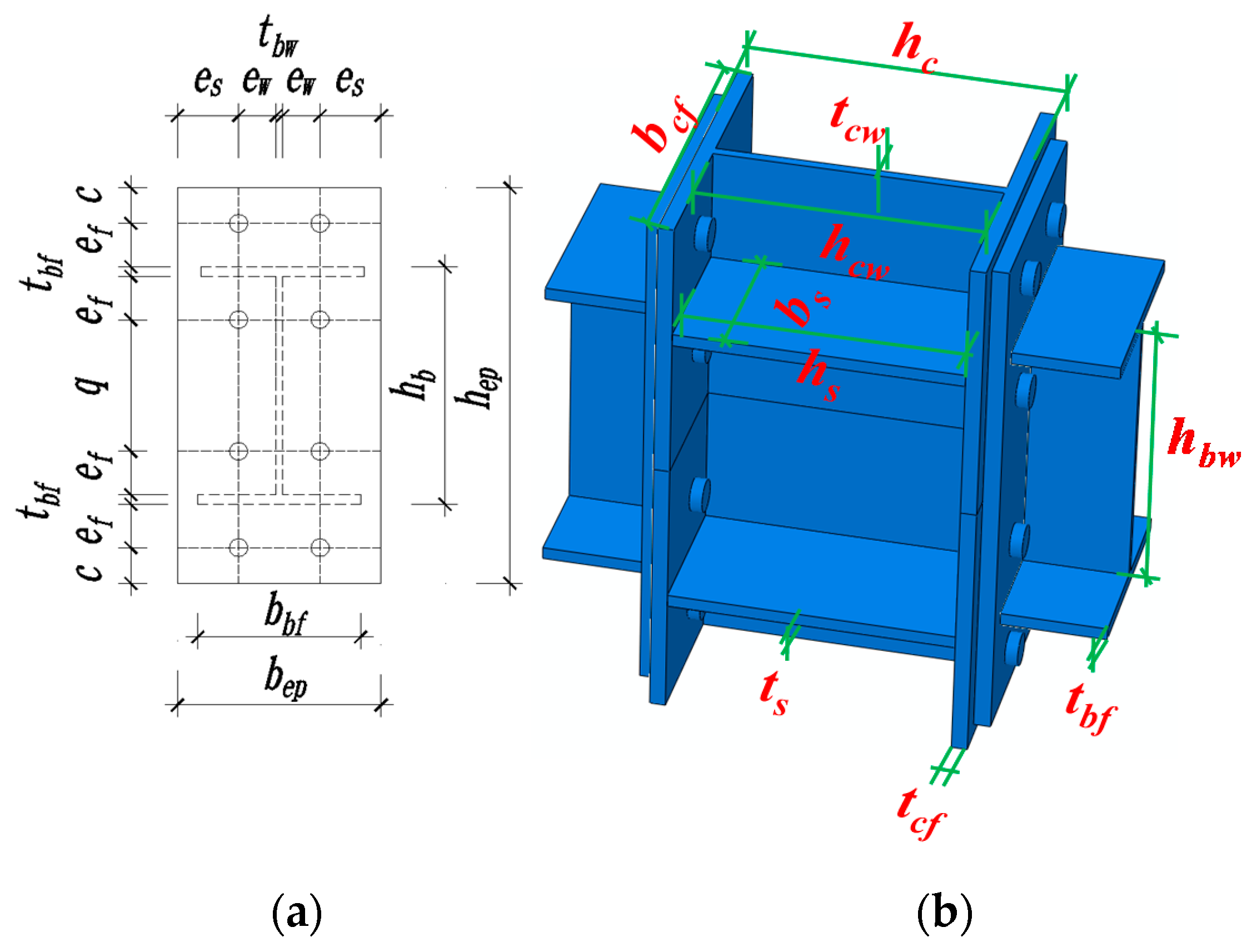
- End-plate height: hep = hb + 2 (ef + c). As shown in Figure 1a, where hep and hb are the height of the end-plate and the height of the beam, respectively. ef is the distance from the top row of bolts to the outer edge of the beam flange surface, and c is the distance from the top row of bolts to the outer edge of the end-plate. ef and c are 55 mm and 45 mm from the end-plate of the test specimen.
- (2)
- End-plate width: bep = tbw+2 (es + ew) and bbf ≤ bep ≤ bcf. As displayed in Figure 1a, where bep, bbf, and bcf are the end-plate width, beam flange width, and column flange width, respectively. In general, when the beam flange width can meet the margin requirements of bolt arrangement, the setting of bep ≥ bbf is very appropriate. Each parameter satisfies the above design formula. For specific values, refer to Figure 2b.
- (3)
- End-plate thickness: In accordance with the “American Steel Structure Design Manual”, the end-plate thickness should not be less than 12 mm. The end-plate thickness should range from 12 to 30 mm. The thickness of the end-plate in this experiment is 16 mm.
- Bolt
- (1)
- Bolt arrangement: Refer to the relevant methods in the American Steel Structure Design Manual. The bolt arrangement requires that the bolts of the end-plate connection should be symmetrically arranged. Two columns of bolts can be used in preference—that is, there are only two bolts in each row. Set a row of bolts on the inside and outside of the beam flange, respectively; according to actual needs, several rows of bolts can be added on the inner side of the flange.
- (2)
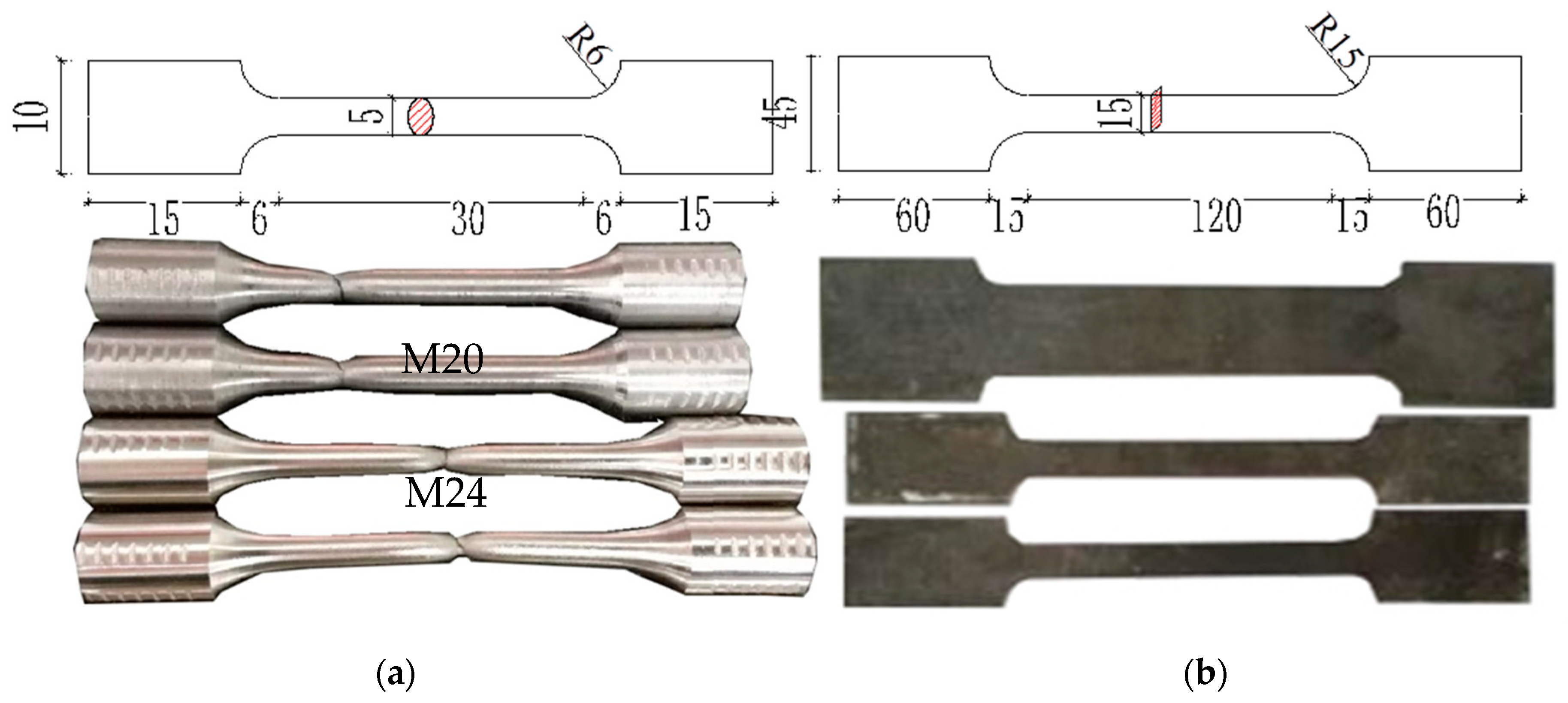
- Bolt selection: We give priority to adopt a high-strength bolt friction-type connection, the diameter is usually 16–30 mm. In this test, two commonly used bolts, M20 and M24, are selected.
- Panel zone
- (1)
- Column web: The “Chinese Code for Steel Structures” and “Chinese Code for Seismic Resistance” put forward the requirements for the thickness of the column webs based on the stability of the panel zone: tcw ≥ (hbw + hcw)/90. As exhibited in Figure 1b, where tcw, hbw, and hcw are the thickness of the column web, the height of the beam web, and the height of the column web, respectively.
- (2)
- Column flange: In this experiment, due to the difference in shear value at the specimen panel zone, the end-plate is used as the intermediate column connection, and the column flanges on both sides of the panel zone are locally thickened. The edge column joints cannot consider this issue.
- (3)
- Column web stiffener: The column web stiffener meets the conditions of ts ≥ tbf, hs = hc − 2tcf and bs = 0.5 (bcf − tcw); that is, the thickness of the stiffener is not less than the thickness of the beam flange, and the width of the stiffener reaches at least the edge of the beam flange. The column web stiffeners are aligned with the beam flange in the thickness direction. As presented in Figure 1b, where ts, tbf, tcf, and tcw are the column web stiffener thickness, beam flange thickness, and column flange thickness, hs and bs are column web stiffener height and width, and hc and bc are column section height and width.
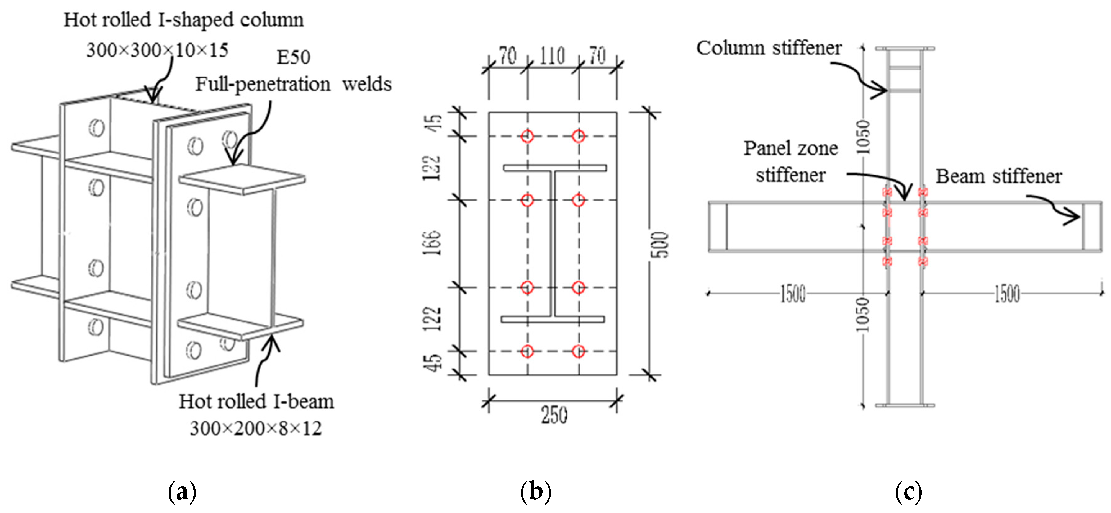
2.2.2. Specimen Configuration
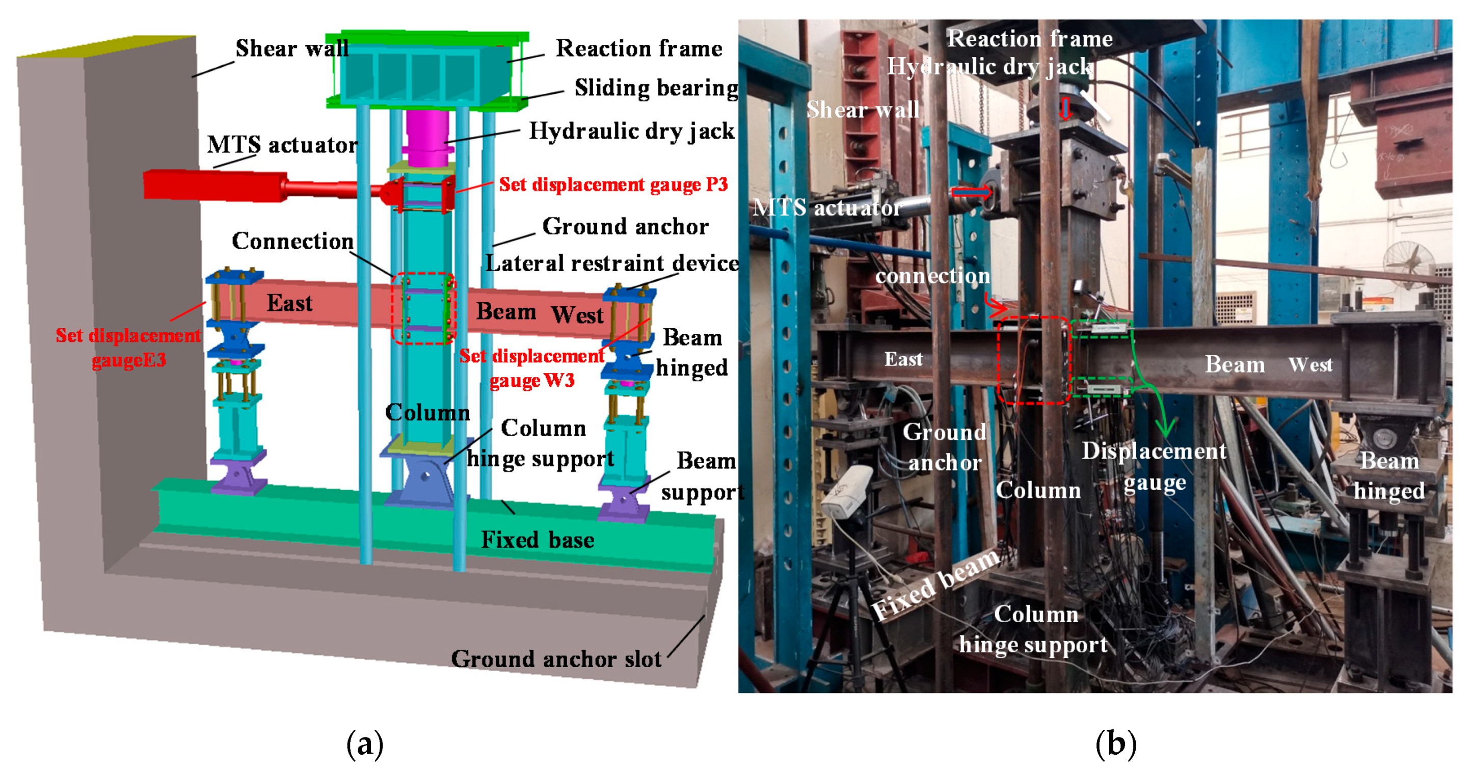
2.3. Experimental Test Setup and Loading Procedure
2.4. Measuring Point Arrangement
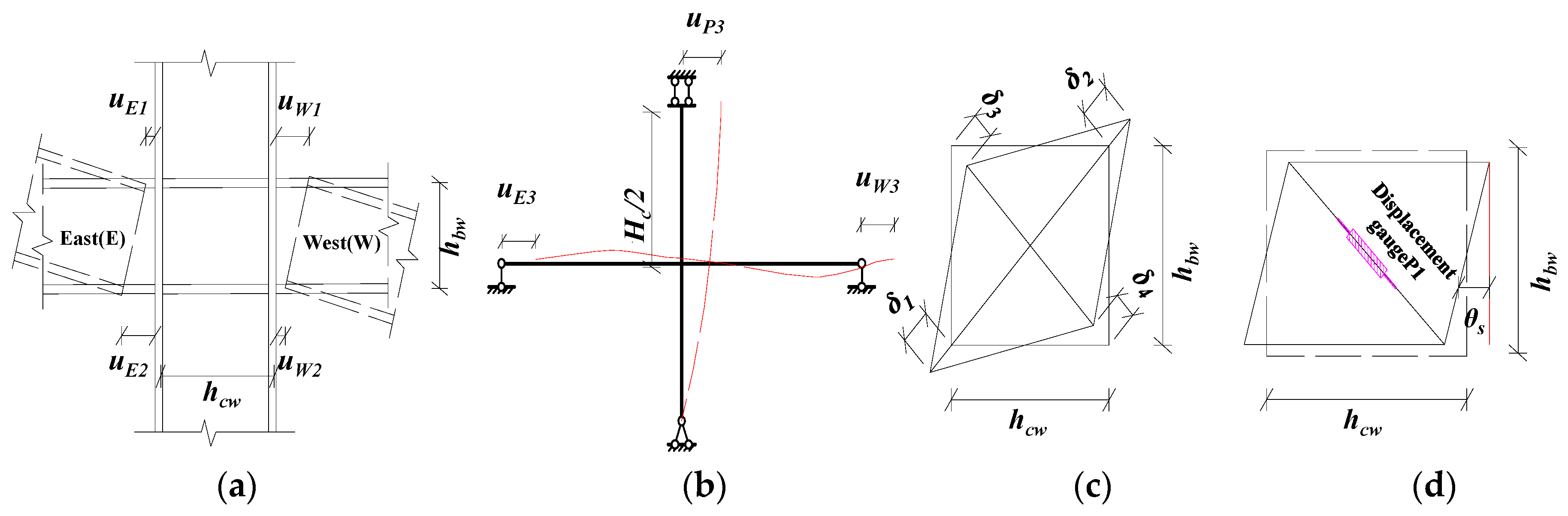
2.5. Measurement of Rotation Angle (θ)
- Relative rotation angle between the end-plate and column flange θep:
- Shear angle of panel zone θs:
- The relative rotation angle of the beam–column joint θg:where HC is the column height. hbw and hcw are the height and width of the panel zone, respectively, corresponding to the spacing between the beam and the centerline of the upper and lower flanges of the column, and the letter u corresponds to the values of the displacement gauges. Through the on-site calibration of the test, the results of the two measurement methods of data analysis, Method 1 and Method 2, can be verified with each other. The overall results are consistent, but there is a scope of application. For example, when the joint is in the elastic stage, the rotation angle of the joints calculated by Equation (2) for calculating θep is accurate. After the connection enters plasticity, the shear angle of the joints panel zone accounts for 2/3 of the total angle, and the rotation of the column also accounts for a large proportion, which no longer satisfies the minor angle method, i.e., sinθ ≠ θ ≠ tanθ ≠ Δ/HC, making the joint angle θgw (θ) calculated by Equation (5) too small. However, for the calculation of θs in Equation (4), when the deformation value of the test is larger than the displacement measurement range used, the displacement of the displacement meter on a single diagonal edge fails, resulting in the ultimate shear deformation of the panel zone that cannot be directly measured accurately. This makes it difficult to accurately reflect the joint’s moment–angle curve from subsequent calculations. In the follow-up study of this paper, the relative rotation angle of the end-plate (θep) and the shear rotation angle (θs) are both adopted by Method 1.
3. Result
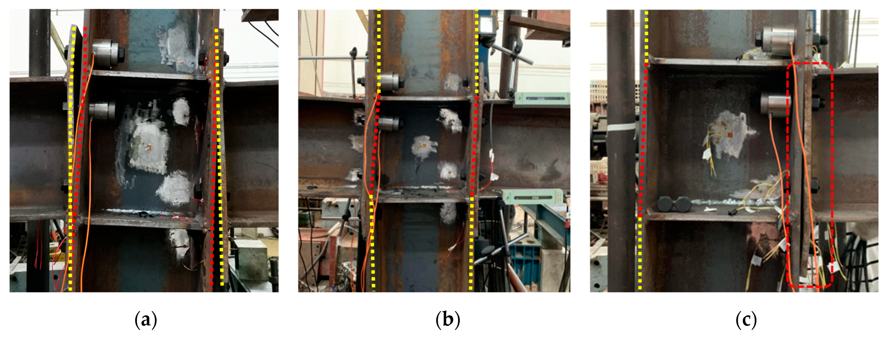
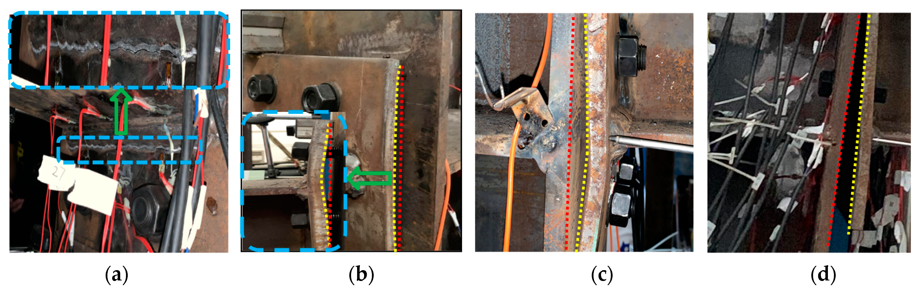
3.1. Test Phenomenon and Failure Modes
3.1.1. Specimen IC-EP1
3.1.2. Specimen IC-EP2
3.1.3. Specimens EC-EP1 and EC-EP2
4. Discussion
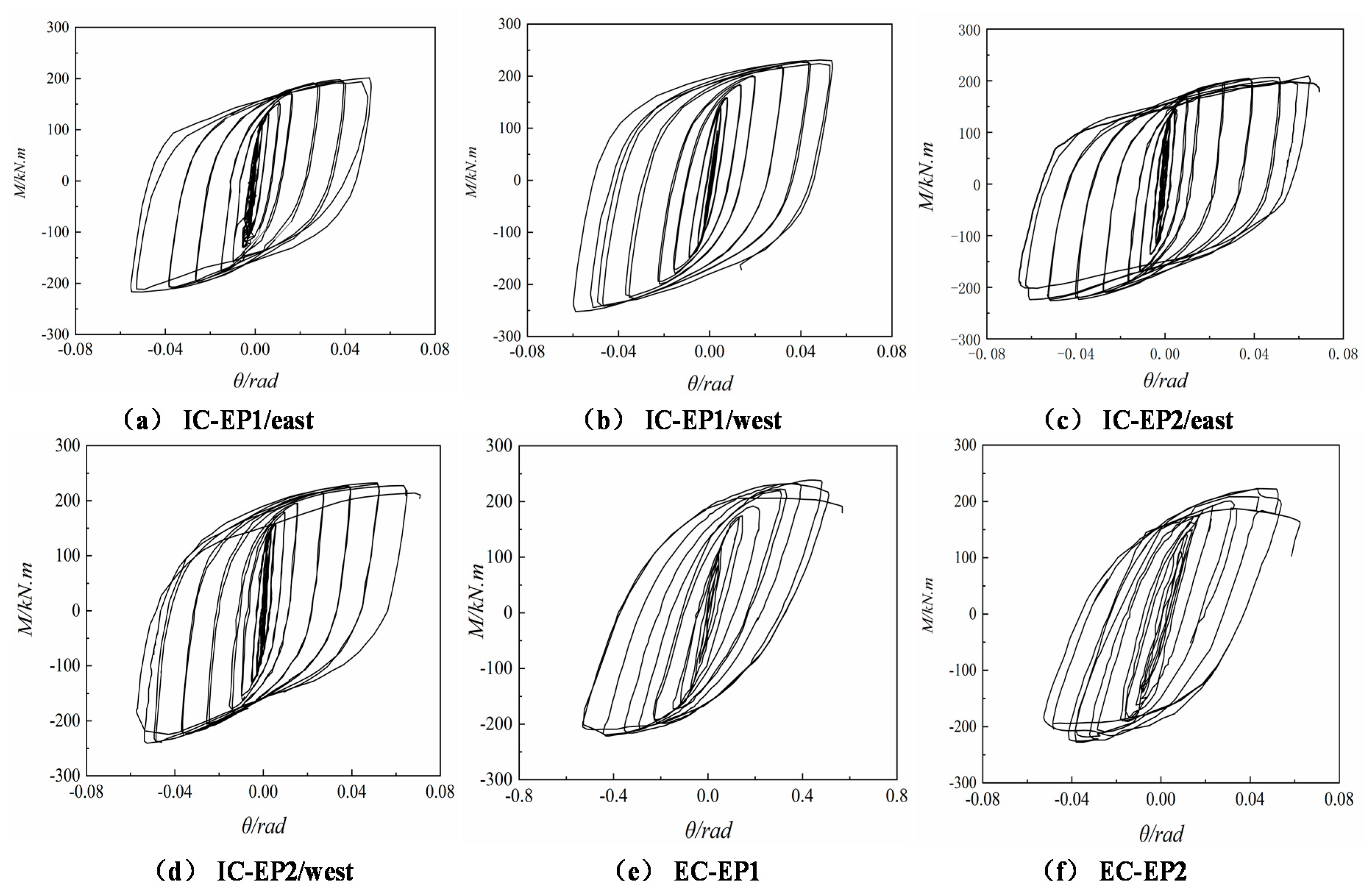
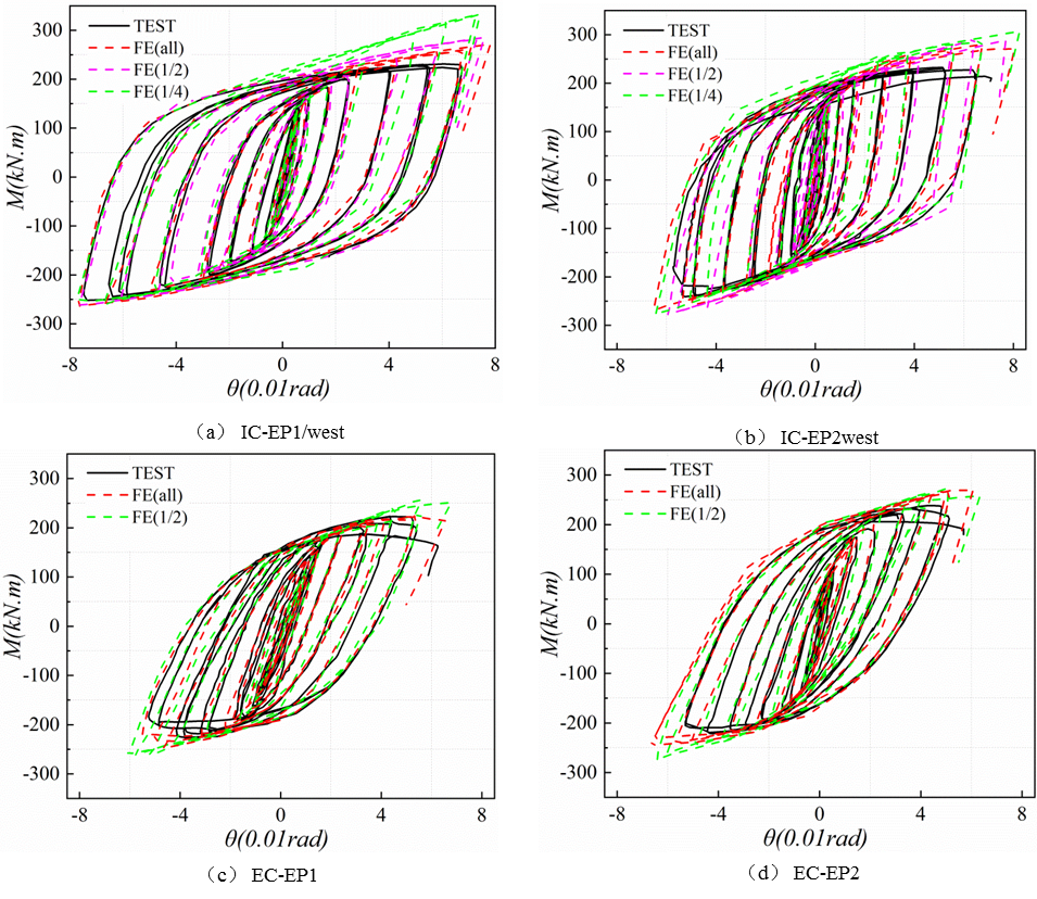
4.1. Moment–Rotation Hysteresis Curves
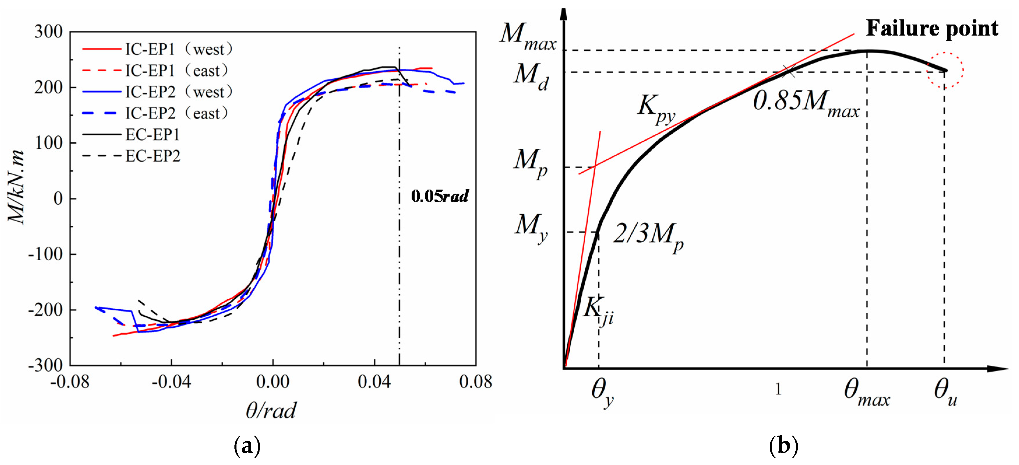
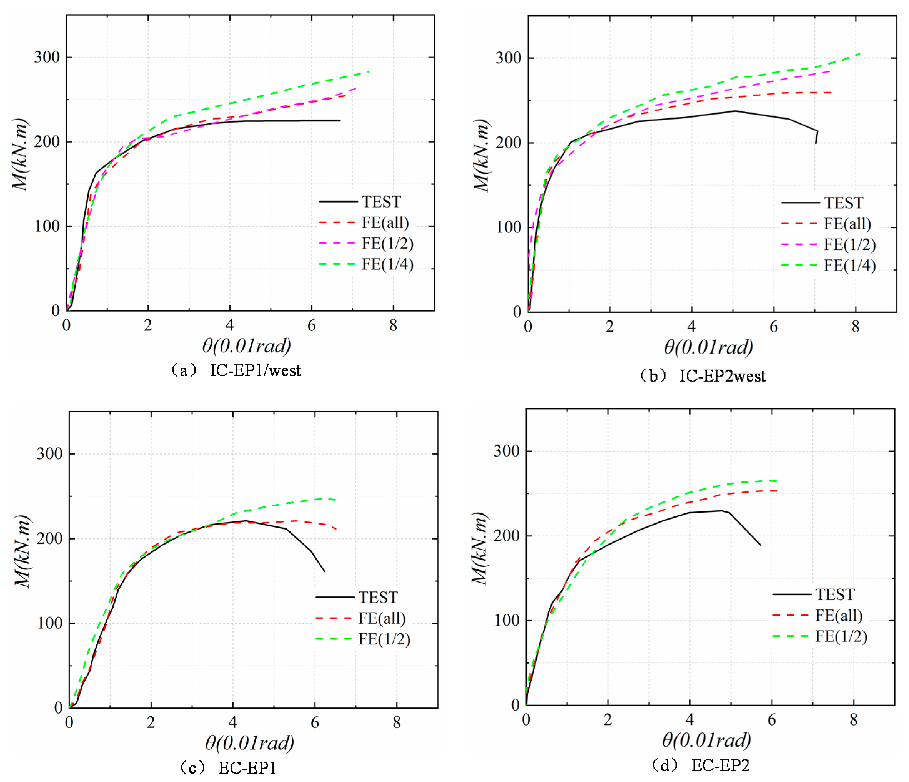
4.2. M–θ Envelope Curves
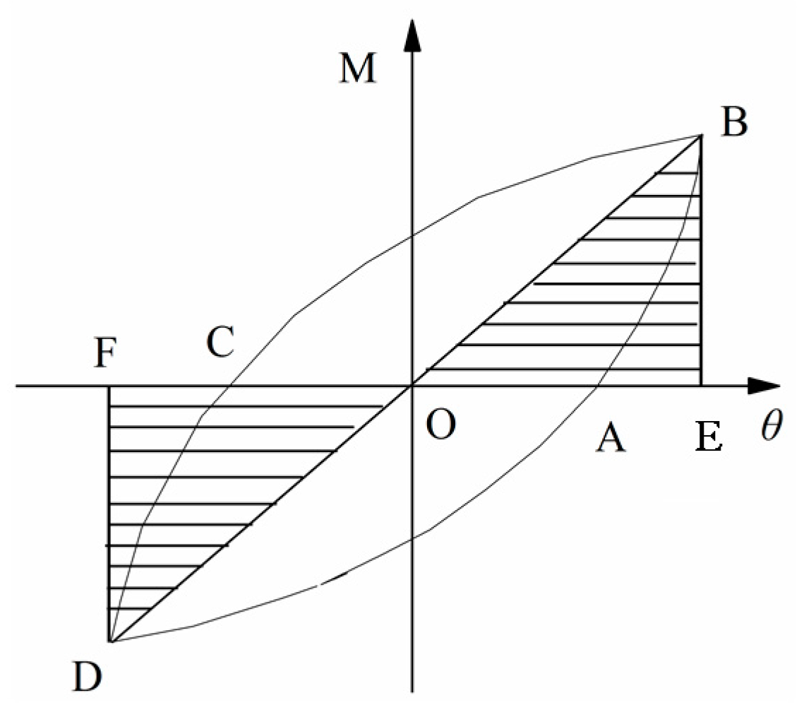
4.3. Energy Dissipation
- (1)
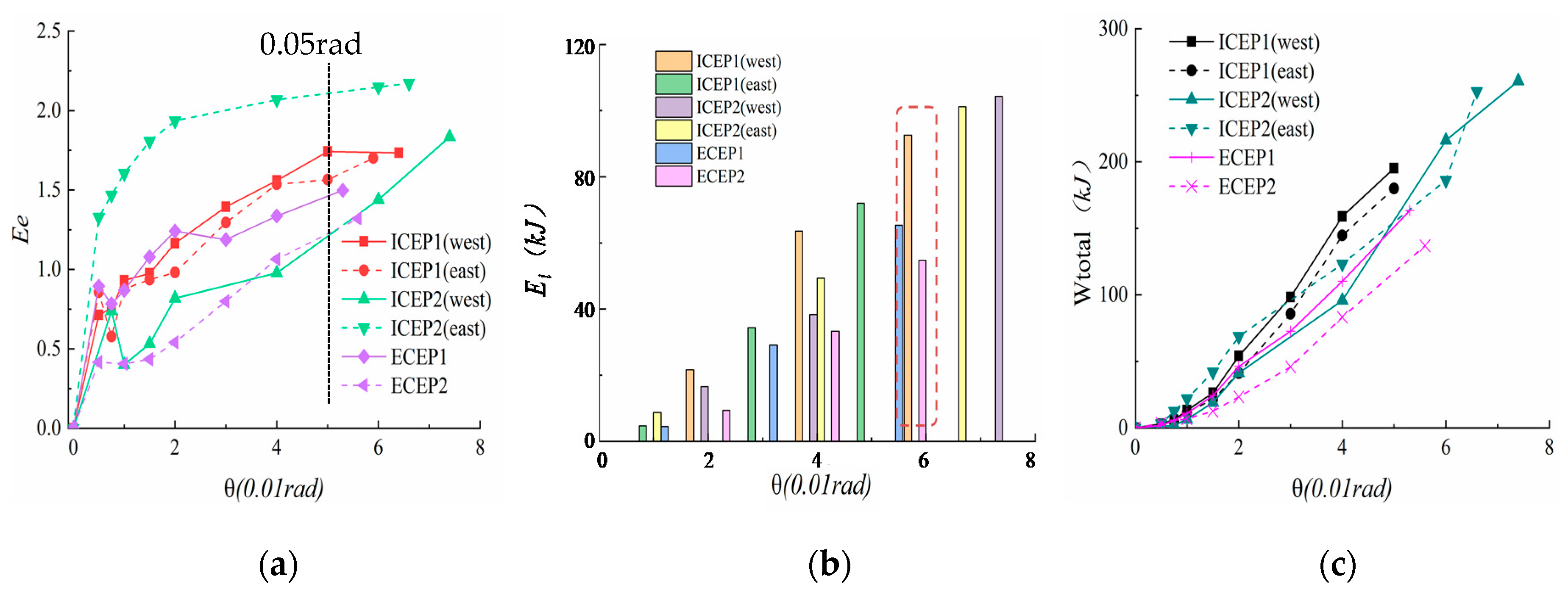
- As shown in Figure 14a, as the cyclic displacement increases, the Ee values of the four specimens change. Under the relative rotation angle of the joints of 0.05 rad, the Ee value of the loaded specimens in all experiments is greater than 1, which indicates that all specimens have acceptable energy dissipation capacity.
- (2)
- Table 6 shows that the energy dissipation coefficient of the IC-EP2 specimen exceeds 2.2 when the specimen is a failure, indicating that this type of joint is an ideal seismic energy dissipation connection. The IC-EP1 and EC-EP1 specimens with the same parameter configuration are only the difference between the single and double-sided end-plates, which increases the total energy consumption of the east and west sides of the IC-EP1 specimen by 30.7% and 41.6%. For the setting of joints, it indicates that for the edge column and the intermediate column, the energy dissipation capacity of the edge columns should be used as the reference value for the lower limit of the design in the seismic energy dissipation design.
- (3)
- Compared with the IC-EP1 and IC-EP2 specimens, the use of bolts with a smaller diameter makes the connection fail prematurely, as displayed in Figure 14c, and the corresponding joint energy consumption is also reduced by about 21%.
- (4)
- As shown in Figure 14b,c, the energy dissipated in each step (Ei) and the cumulative energy dissipation (Wtotal) are constantly increased. At a relative rotation angle of 0.05 rad, the Ei of the four specimens are basically more than 60 kJ, and the cumulative energy dissipation of the intermediate column specimens during failure varies from 170 to 260 kJ, showing that the energy consumption effect of the structure in the early stage is very distinct. The two specimens EC-EP1 and EC-EP2 showed similar responses in the limit state, but the EC-EP2 specimen increased the thickness of the end-plate by 4 mm, corresponding to a 14.5% decrease in total energy consumption.
4.4. Rotation Ability and Ductility
4.5. Classification of the Tested Connections
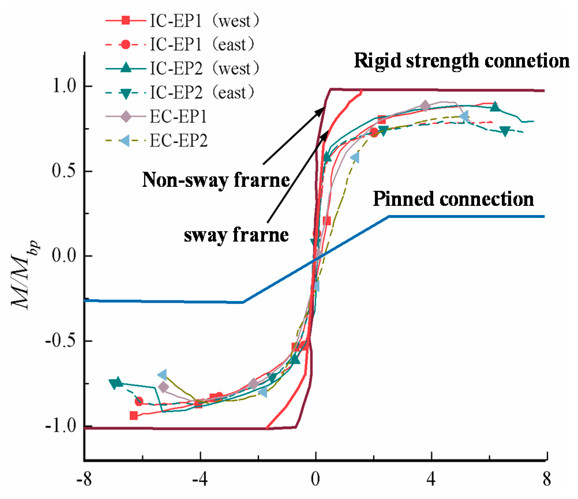
- Classification according to stiffness: when Kji ≥ 8EIb/Lb (braced frame, EIb/Lb is the linear stiffness of the beam, where E, Ib and Lb are the elasticity modulus, second moment of area, and the length of the steel beam, respectively) or Kji ≥ 25EIb/Lb (non-braced frame), it is a rigid connection; Kji ≤ 0.5EIb/Lb, it is nominally pinned; 0.5EIb/Lb < Kji < 8EIb/Lb (braced frame) or 0.5EIb/Lb < Kji < 25EIb/Lb (non-braced frame), it is a semi-rigid connection.
- Classification according to strength: when Md ≥ Mbp (where Mbp represents the design plastic flexural resistance of the steel beam), it is a full-strength connection; when 0.25Mbp < Md < Mbp, it is a partial-strength connection; when 0.25Mbp > Md, it is a nominally pinned connection.
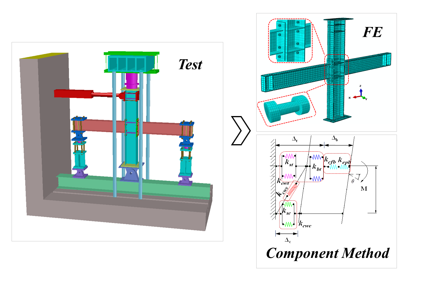
5. Finite Element Verification and Exploratory Numerical Research
5.1. Finite Element Modeling
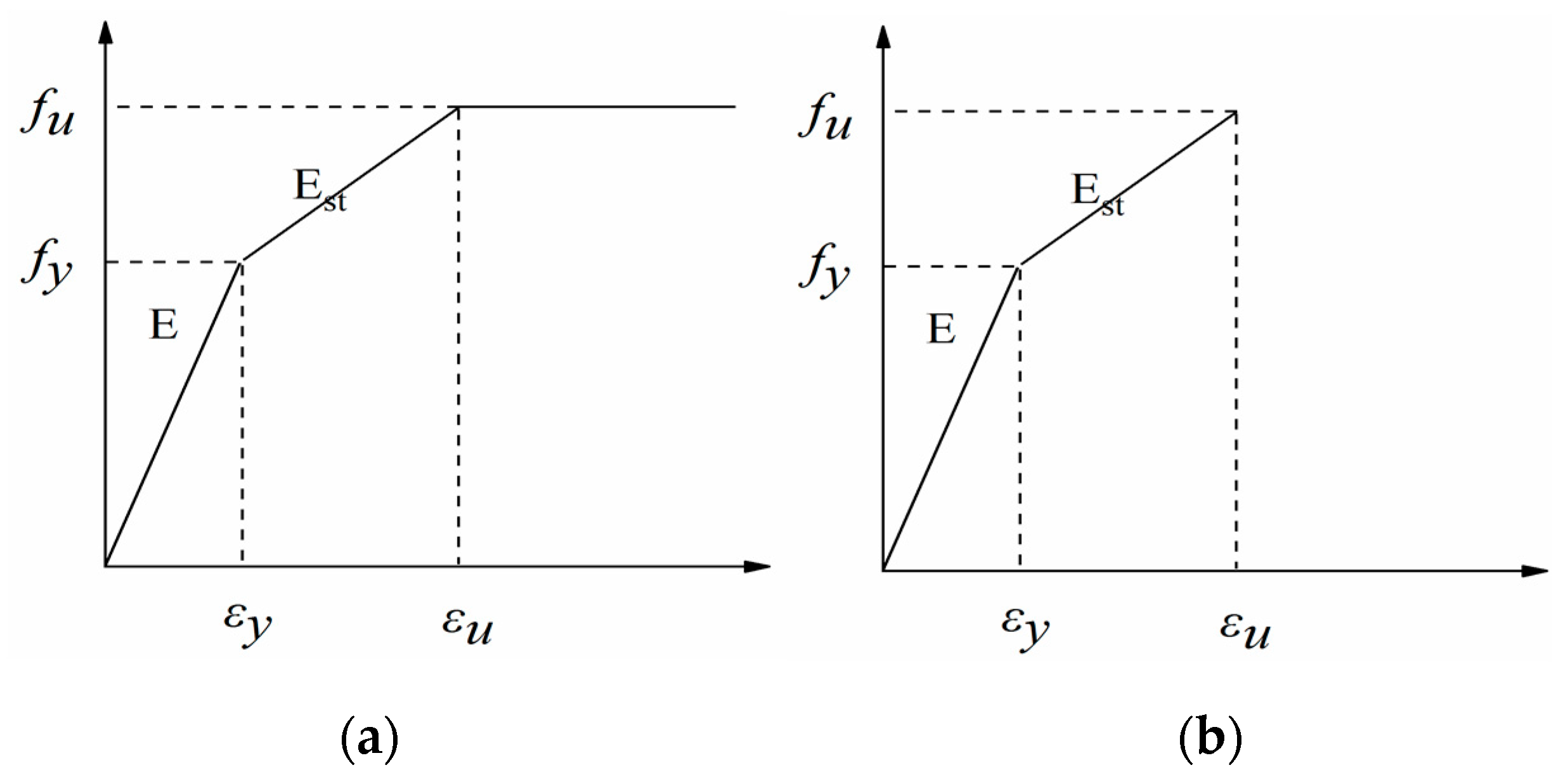
5.1.1. Material Models
5.1.2. Model Description
5.2. Validation
5.3. Results and Discussion
6. Conclusions
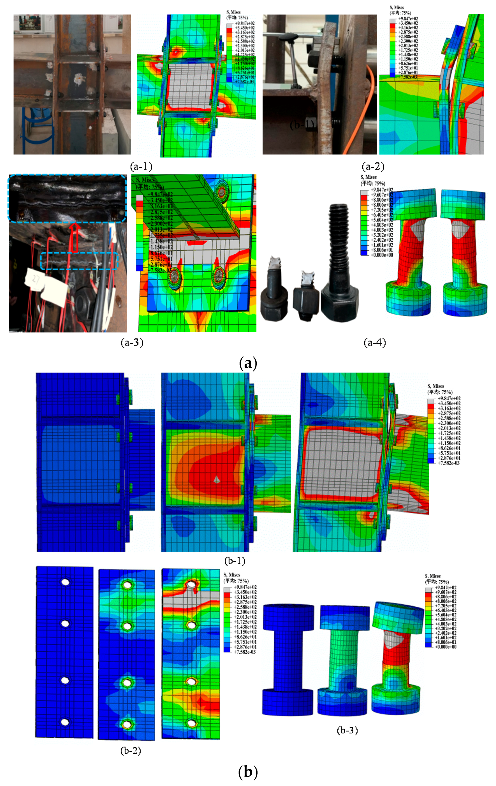
- The bolt diameter approximately equal to the thickness of the end-plate can effectively avoid premature connection failure and excessive bending of the end plate. Loaded to 6% drift ratio, the column web basically reaches the buckling state, and the shear deformation of the panel zone is obvious. The final failure mode is the tear of the weld between the beam flange and the end-plate (WEP-BF); when the bolt diameter is smaller than the thickness of the end-plate, the failure mode is bolt break (BF), and then the end-plate and the column web are separated, causing brittle failure of the joint. More importantly, three typical failure modes are proposed for the bolts at the connection. According to the bolts, the angle of the failure surface is divided into failure modes I, II, and III, and the bolt failure modes are related to its stress state.
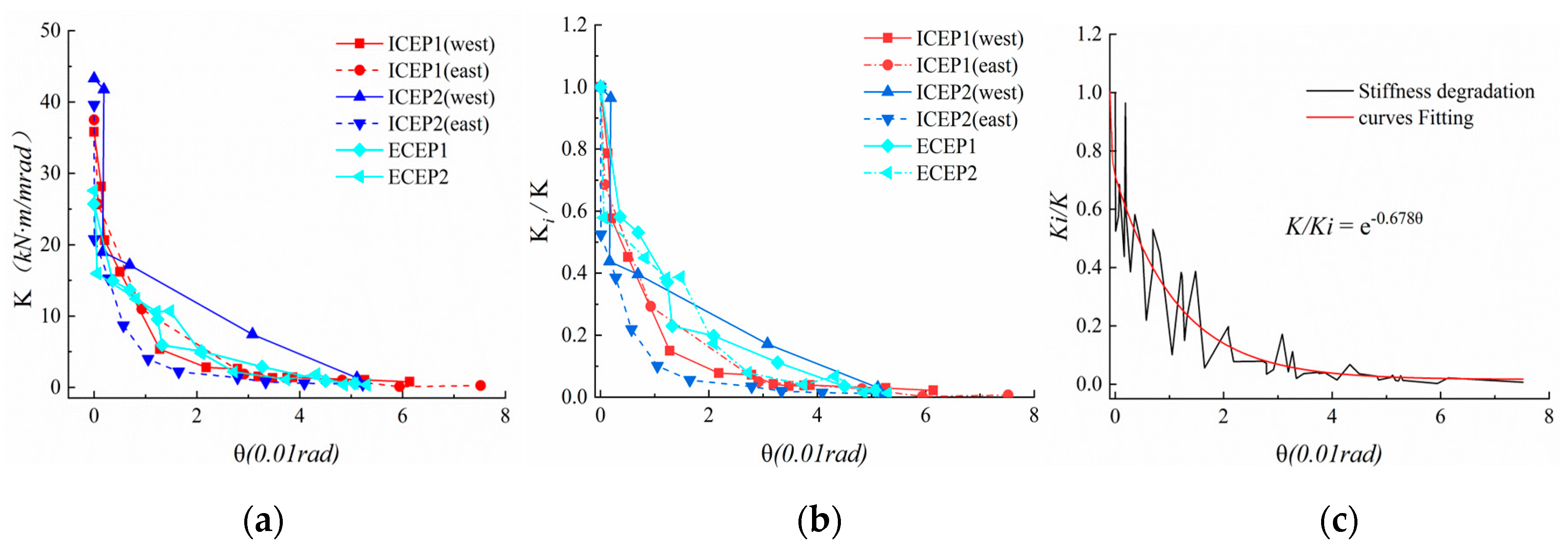
- The observation results show that the hysteresis curve of the extended end-plate connection is plum and that the intermediate column joints have better rotational stiffness and rotation ability than the edge column joints. As far as the intermediate column joints are concerned, the joint stiffness is more than 80% greater than that of the edge column joints. However, the ultimate flexural resistance capacity of both is not much different, and the difference in the mechanical behaviors of the two sides’ connection of the intermediate column joints is slight. According to the EC3 classification, the joints under this loading method are still semi-rigid and partially equal-strength connection joints; the energy dissipation coefficients of the specimen joints are all over 1.3, which is the ideal seismic energy dissipation joint. During the whole loading process, the joint stiffness degrades exponentially; at a rotation angle of 0.05 rad, all components of the specimen basically enter the plastic state, and the joint stiffness is less than 0.1 times the initial rotational stiffness.
- The column top-side loading scheme is different from the previous beam tip loading method, and the plastic hinge is also transferred from the beam end to the panel zone of the column web, which manifests itself in the form of excessive shear. This is consistent with the failure mode of some joints during the earthquake. For the comparison of the two loading methods, the joints are in the elastic stage, and the mechanical indicators such as the initial rotational stiffness are basically the same. However, after the joints enter the plastic stage, the different force transmission mechanisms result in the failure model and the ultimate flexural resistance being different.
- The ductility coefficient μθ of the extended end-plate joints is in the range of 9.4 to 16.1, the yield angle θy is about (0.78 to 1.6) [θe], and the plastic limit rotation angle θu of the joint is about (2.5 to 3.5) [θp]. The analysis results with the elastic layer angular displacement limit and the elastic–plastic layer angular displacement limit of the steel structure show that such joints have good ductility and meet the requirements of seismic design.
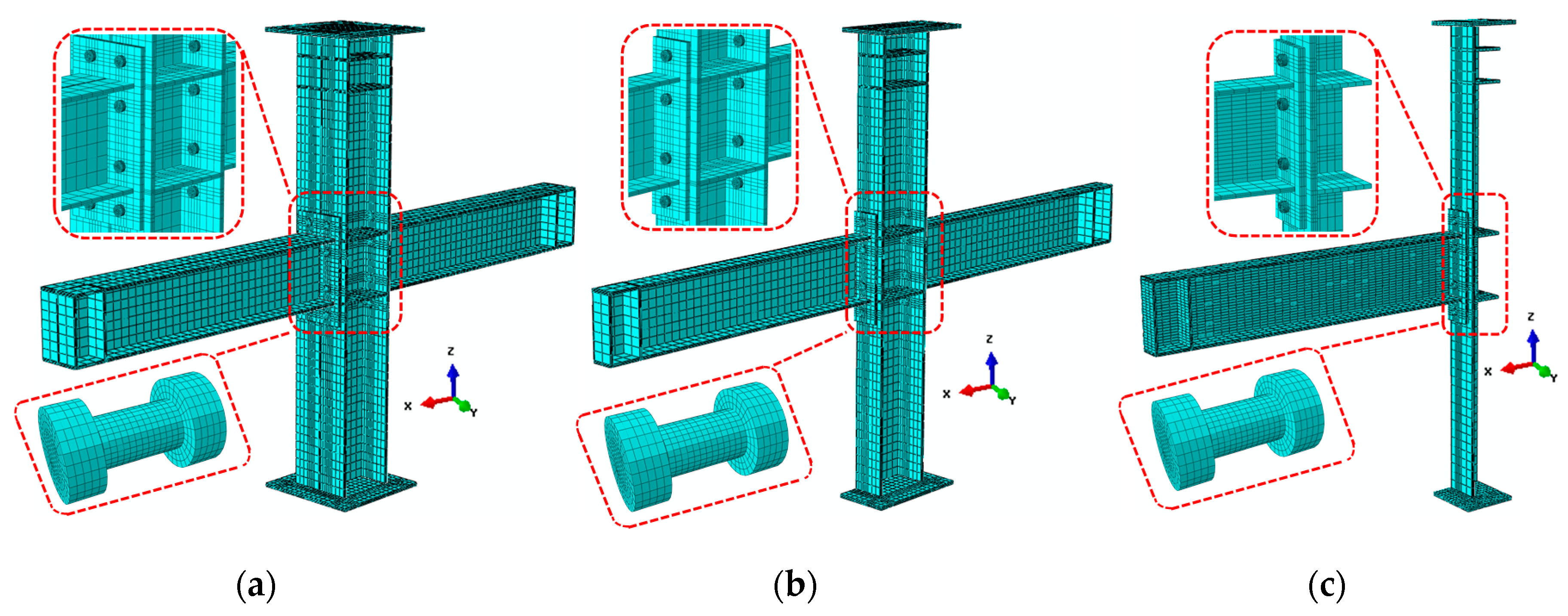
- Use the ABAQUS/Standard module to establish the finite element full-model, symmetric half-model, and quarter-model of the connected joints. These FE models were used to cross-validate the test results. The results show that the half-model and the quarter-model can be used to simulate the intermediate column and edge column joints’ connection behavior, respectively. More importantly, FE can accurately predict the rotational stiffness of the joints in the elastic stage with sufficient accuracy. An effective simulation is given for the location where the failure occurs in the test. The results of finite element analysis are in agreement with the test, which demonstrated the reliability of the experimental results.
Author Contributions
Funding
Acknowledgments
Conflicts of Interest
References
- Chen, C.-C.; Chen, S.-W.; Chung, M.-D.; Lin, M.-C. Cyclic behaviour of unreinforced and rib-reinforced moment connections. J. Constr. Steel Res. 2005, 61, 1–21. [Google Scholar] [CrossRef]
- Akiyama, H. Evaluation of fractural mode of failure in steel structures following Kobe lessons. J. Constr. Steel Res. 2000, 55, 211–227. [Google Scholar] [CrossRef]
- Mahin, S.A. Lessons from damage to steel buildings during the Northridge earthquake. Eng. Struct. 1998, 20, 261–270. [Google Scholar] [CrossRef]
- Tremblay, R.; Filiatrault, A.; Timler, P.; Bruneau, M. Performance of steel structures during the 1994 Northridge earthquake. Can. J. Civ. Eng. 1995, 22, 338–360. [Google Scholar] [CrossRef]
- Jaspart, J.-P. General report: Session on connections. J. Constr. Steel Res. 2000, 55, 69–89. [Google Scholar] [CrossRef]
- Krishnamurthy, N. A Fresh Look at Bolted End-Plate Behavior and Design. Eng. J. 1978, 15, 39–49. [Google Scholar]
- Sherbourne, A.N.; Bahaari, M.R. 3D Simulation of End-Plate Bolted Connections. J. Struct. Eng. -Asce 1994, 120, 3122–3136. [Google Scholar] [CrossRef]
- Abidelah, A.; Bouchaïr, A.; Kerdal, D.J.J. Experimental and analytical behavior of bolted end-plate connections with or without stiffeners. J. Constr. Steel Res. 2012, 76, 13–27. [Google Scholar] [CrossRef]
- Guo, B.; Gu, Q.; Liu, F. Experimental Behavior of Stiffened and Unstiffened End-Plate Connections under Cyclic Loading. J. Struct. Eng. -Asce 2006, 132, 1352–1357. [Google Scholar] [CrossRef]
- Popov, E.P.; Tsai, K.C. Performance of Large Seismic Steel Moment Connections under Cyclic Loads. Eng. J. 1989, 26, 51–60. [Google Scholar]
- Grimsmo, E.L.; Clausen, A.H.; Langseth, M.; Aalberg, A. An experimental study of static and dynamic behaviour of bolted end-plate joints of steel. Int. J. Impact Eng. 2015, 85, 132–145. [Google Scholar] [CrossRef]
- Ioannides, S.A.; Tarpy, T.S. Practical application of semi-rigid beam to column end-plate connectors. Appl. Math. Model. 1980, 4, 23–27. [Google Scholar] [CrossRef]
- Aribert, J.; Lauchal, A.; Nawawy, O.J.C.M. Elastic-plastic modelization of the resistance of a column in the compression region. Constr. Met. 1981, 2, 122–131. [Google Scholar]
- Shi, G.; Shi, Y.; Wang, Y.; Bradford, M.A. Numerical simulation of steel pretensioned bolted end-plate connections of different types and details. Eng. Struct. 2008, 30, 2677–2686. [Google Scholar] [CrossRef]
- Brando, G.; Sarracco, G.; De Matteis, G.J.J. Strength of an aluminum column web in tension. J. Struct. Eng. -Asce 2015, 141, 04014180. [Google Scholar] [CrossRef]
- Mostafa Radmehr, P.H. The seismic reliability analysis of moment resisting frames with bolted end-plate connection. J. Constr. Steel Res. 2020, 171, 106134. [Google Scholar] [CrossRef]
- Construction, A.I. Manual of Steel Construction: Allowable Stress Design; American Institute of Steel Construction: Chicago, IL, USA, 1989. [Google Scholar]
- Load, A. Resistance Factor Design Specification for Structural Steel Buildings; American Institute of Steel Construction: Chicago, IL, USA, 1999. [Google Scholar]
- Standardization, E. EN1993-1-8. Eurocode 3: Design of Steel Structures-Part 1-8 In Design of Joints; European Committee for Standardization: Brussels, Belgium, 2005. [Google Scholar]
- Zhan, W.; Wang, T. Experimental research and finite element analysis of the connection of weak shaft end plates of semi-rigid steel frame beams and columns China Civ. Eng. J. 2012, 45, 83–89. (In Chinese) [Google Scholar]
- Faella, C.; Piluso, V.; Rizzano, G. Structural Steel Semirigid Connections: Theory, Design, and Software; CRC press: Boca Raton, FL, USA, 1999; Volume 21. [Google Scholar]
- Wang, P.; Pan, J. Experimental and analytical behavior of stiffened angle joints. Steel Compos. Struct. 2018, 26, 67–78. [Google Scholar]
- PRC, M. ChineseStandard.GB 50017-2017. Code for Design of Steel Structure; China Building Industry Press: Beijing, China, 2017. [Google Scholar]
- PRC, M. ChineseStandard.GB/T228.1–2010 Metallic Materials Tensile Test Part 1: Tensile Test Method at Room Temperature; China Architecture and Building Press: Beijing, China, 2010. [Google Scholar]
- Clark, P.; Frank, K.; Krawinkler, H.; Shaw, R. Protocol for fabrication, inspection, testing, and documentation of beam-column connection tests and other experimental specimens. In SAC Steel Project Background Document. October, Report No. SAC/BD-97/02; SAC Joint Venture: Sacramento, CA, USA, 1997. [Google Scholar]
- Shi, Y.; Shi, G.; Wang, Y. Experimental and theoretical analysis of the moment–rotation behaviour of stiffened extended end-plate connections. J. Constr. Steel Res. 2007, 63, 1279–1293. [Google Scholar] [CrossRef]
- Gang, S.; Feng, Y.; Horda; Shi, Y.-J.; Yuanqing, W. The theoretical model and measuring calculation method of the beam-to-column joint rotation in steel frames. Eng. Mech. 2012, 29, 52–60. (In Chinese) [Google Scholar]
- Venture, S.J.; Committee, G.D.; Hamburger, R.O. Interim Guidelines Advisory No. 1: Supplement to FEMA-267 Interim Guidelines: Evaluation, Repair, Modification and Design of Welded Steel Moment Frame Structures; Federal Emergency Management Agency: Washington, DC, USA, 1997.
- Park, R.; Paulay, T. Reinforced Concrete Structures; John Wiley & Sons: Hoboken, NJ, USA, 1975. [Google Scholar]
- Peng, F.; Hanlin, Q.; Leiping, Y. Discussion and definition on yield pointsof materials, members and structures. Eng. Mech. 2017, 3, 36–46. (In Chinese) [Google Scholar]
- GB50011-2010, Code for Seismic Design of Buildings; China Architecture and Building Press: Beijing, China, 2010.
- D’Alessandro, E.; Brando, G.; De Matteis, G.J.P. Buildings, Design charts for end-plate beam-to-column steel joints. Struct. Build. 2018, 171, 444–462. [Google Scholar] [CrossRef]
- ABAQUS Analysis User’s Manual ABAQUS Standard; Version 6.14; SIMULIA: Johnston, RI, USA, 2014.
- El-Tawil, S.J.E.J.-A.I. Panel zone yielding in steel moment connections. Eng. J. (N. Y.) 2000, 37, 120–131. [Google Scholar]
- Maggi, Y.; Gonçalves, R.; Leon, R.; Ribeiro, L. Parametric analysis of steel bolted end plate connections using finite element modeling. J. Constr. Steel Res. 2005, 61, 689–708. [Google Scholar] [CrossRef]


| Joints Type | Specimen | End-Plate Thickness (mm) | Bolt Diameter (mm) | Initial Tightening Torque (N·m) | Final Tightening Torque (N·m) | Bolt Grade | Fpre (kN) | Fc (kN) |
|---|---|---|---|---|---|---|---|---|
| Intermediate column joint | IC-EP1 | 16 | 20 | 280 | 446 | 10.9 | 155 | 1211 |
| IC-EP2 | 16 | 24 | 400 | 760 | 10.9 | 225 | 1211 | |
| Edge column joint | EC-EP1 | 16 | 20 | 280 | 446 | 10.9 | 155 | 1211 |
| EC-EP2 | 20 | 20 | 280 | 446 | 10.9 | 155 | 1211 |
| Sample | t or d (mm) | E/GPa | fy/MPa | fu/MPa | εy/% | εu/% | A/% |
|---|---|---|---|---|---|---|---|
| End-plate 1 | 16 | 210.21 | 366.2 | 541.4 | 0.357 | 50.9 | 27.6 |
| End-plate 2 | 20 | 212.65 | 364.3 | 537.6 | 0.509 | 53.6 | 25.5 |
| Column web | 10 | 207.59 | 385.1 | 540.8 | 0. 378 | 28.4 | 27.6 |
| Column flange | 15 | 205.78 | 371.7 | 557.4 | 0.351 | 52.4 | 19.6 |
| Beam web | 8 | 199.47 | 390.5 | 580.1 | 0.343 | 42.5 | 30.4 |
| Beam flange | 12 | 206.85 | 358.7 | 564.6 | 0.475. | 38.6 | 26.9 |
| Stiffener | 12 | 208.35 | 354.6 | 571.5 | 0.458 | 29.7 | 28.1 |
| M20 bolt | 20 | 209.58 | 998.7 | 1165.7 | 0.487 | 9.5 | 49.8 |
| M24 bolt | 24 | 206.87 | 976.4 | 1198.5 | 0.513 | 7.6 | 50.6 |
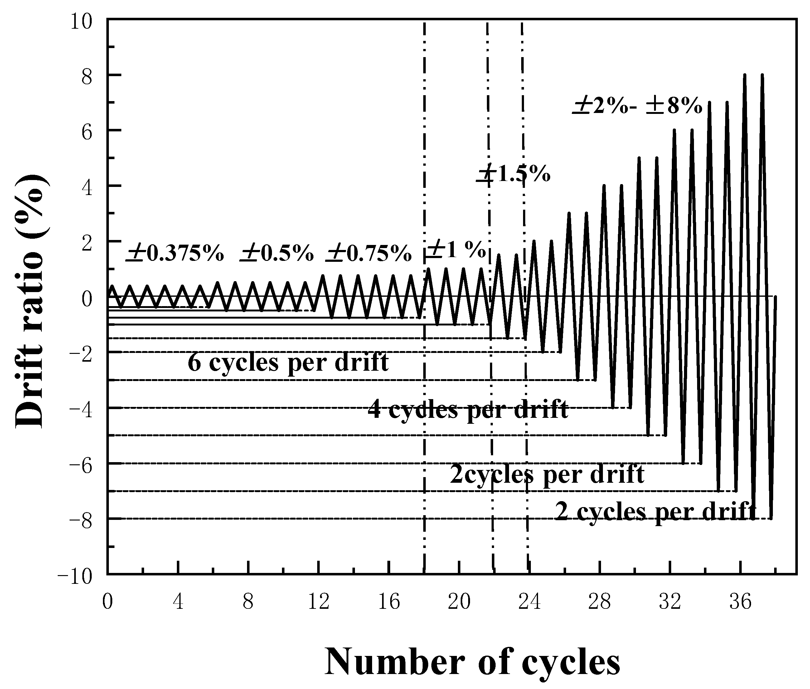
| θdr(rad) | 0.00375 | 0.005 | 0.0075 | 0.01 | 0.015 | 0.02 | 0.03 | 0.04 | 0.05 | 0.06 | 0.07 | 0.08 |
| Displacement(mm) | 7.785 | 10.5 | 15.75 | 21 | 31.5 | 42 | 63 | 84 | 105 | 126 | 147 | 168 |
| n | 6 | 6 | 6 | 4 | 2 | 2 | 2 | 2 | 2 | 2 | 2 | 2 |
| Failure Classification | Failure Mode I | Failure Mode II | Failure Mode III |
|---|---|---|---|
| Destruction surface angle | 0° | 45° | 0–45° |
| Pattern | Tensile failure | Shear failure | Both failure patterns exist |
| Phenomenon | Bolt shank breakage and contraction | Bolt shank oblique shear failure | Bolt shank axis bending and necking |
| Bolt failure location | The first row of specimen EC-EP1 and EC-EP2 | The bottom rows of IC-EP2 specimen | The bottom two rows of IC-EP2 specimen |
| Corresponding figure | Figure 9a,c,d | Figure 9b | Figure 9e |
| Specimen | Kji (kN·m/mrad) | My (kN·m) | Md (kN·m) | Mp (kN·m) | Mmax (kN·m) | θmax (rad) | θy (mrad) | θu (rad) | μθ | |
|---|---|---|---|---|---|---|---|---|---|---|
| IC-EP1 | west | 55.8 | 130.4 | 213.4 | 195.6 | 251.1 | 0.05 | 6.7 | 0.06 | 9.0 |
| east | 57.5 | 124.1 | 203.2 | 186.1 | 239.1 | 0.06 | 6.5 | 0.06 | 9.2 | |
| IC-EP2 | west | 63.3 | 138.6 | 203.8 | 208.3 | 239.8 | 0.07 | 7.9 | 0.07 | 8.9 |
| east | 62.6 | 132.1 | 194.4 | 198.1 | 228.7 | 0.06 | 7.1 | 0.06 | 8.5 | |
| EC-EP1 | - | 25.7 | 130.7 | 201.1 | 195.6 | 236.6 | 0.04 | 4.7 | 0.05 | 10.6 |
| EC-EP2 | - | 27.6 | 120.1 | 191.9 | 180.1 | 225.8 | 0.04 | 5.1 | 0.05 | 9.8 |
| Specimen | Ee | ξe | Wtotal | Δ (%) | |
|---|---|---|---|---|---|
| IC-EP1 | W | 1.73 | 0.276 | 191.43 | 41.6 |
| E | 1.70 | 0.271 | 179.60 | 30.7 | |
| IC-EP2 | W | 2.21 | 0.352 | 260.69 | 59.5 |
| E | 2.22 | 0.353 | 252.90 | 54.7 | |
| EC-EP1 | - | 1.50 | 0.238 | 163.44 | 0 |
| EC-EP2 | - | 1.35 | 0.214 | 139.66 | −14.5 |
| Material Type | fy/MPa | fu/MPa | εy/% | E/GPa | Est/GPa |
|---|---|---|---|---|---|
| Q345B steel | 370.16 | 556.20 | 0.40 | 207.27 | 0.02E |
| 10.9-grade high strength bolt | 987.55 | 1182.10 | 0.50 | 208.23 | 0.11E |
| Specimen | Method | Kji (kN·m/mrad) | My (kN·m) | θy (mrad) | KFE/KTest | Method | Kji (kN·m/mrad) | My (kN·m) | θy (mrad) | KFE/KTest |
|---|---|---|---|---|---|---|---|---|---|---|
| IC-EP1/west | Test | 55.8 | 130.4 | 6.7 | - | FE(1/2) | 53.5 | 123.2 | 5.3 | 0.96 |
| FE(all) | 57.8 | 136.7 | 6.1 | 1.04 | FE(1/4) | 52.2 | 155.8 | 5.7 | 0.94 | |
| IC-EP2/west | Test | 63.3 | 138.6 | 7.9 | - | FE(1/2) | 65.6 | 150.6 | 6.7 | 1.04 |
| FE(all) | 64.9 | 146.3 | 7.8 | 1.03 | FE(1/4) | 66.1 | 163.2 | 5.5 | 1.04 | |
| EC-EP1 | Test | 25.7 | 130.7 | 4.7 | - | FE(1/2) | 28.5 | 153.8 | 4.1 | 1.11 |
| FE(all) | 26.3 | 141.3 | 5.3 | 1.02 | ||||||
| EC-EP2 | Test | 27.6 | 120.1 | 5.1 | - | FE(1/2) | 29.8 | 135.7 | 3.7 | 1.08 |
| FE(all) | 30.9 | 130.5 | 4.9 | 1.12 |
© 2020 by the authors. Licensee MDPI, Basel, Switzerland. This article is an open access article distributed under the terms and conditions of the Creative Commons Attribution (CC BY) license (http://creativecommons.org/licenses/by/4.0/).
Share and Cite
Luo, L.; Qin, J.; Zhao, D.; Wu, Z. Seismic Behavior of Extended End-Plate Connections Subjected to Cyclic Loading on the Top-Side of the Column. Materials 2020, 13, 3724. https://doi.org/10.3390/ma13173724
Luo L, Qin J, Zhao D, Wu Z. Seismic Behavior of Extended End-Plate Connections Subjected to Cyclic Loading on the Top-Side of the Column. Materials. 2020; 13(17):3724. https://doi.org/10.3390/ma13173724
Chicago/Turabian StyleLuo, Liang, Jiangui Qin, Dongzhuo Zhao, and Zhiwei Wu. 2020. "Seismic Behavior of Extended End-Plate Connections Subjected to Cyclic Loading on the Top-Side of the Column" Materials 13, no. 17: 3724. https://doi.org/10.3390/ma13173724
APA StyleLuo, L., Qin, J., Zhao, D., & Wu, Z. (2020). Seismic Behavior of Extended End-Plate Connections Subjected to Cyclic Loading on the Top-Side of the Column. Materials, 13(17), 3724. https://doi.org/10.3390/ma13173724