Numerical Simulation and Experimental Confirmation of a Bimetallic Pipe Forming Process

Abstract
1. Introduction
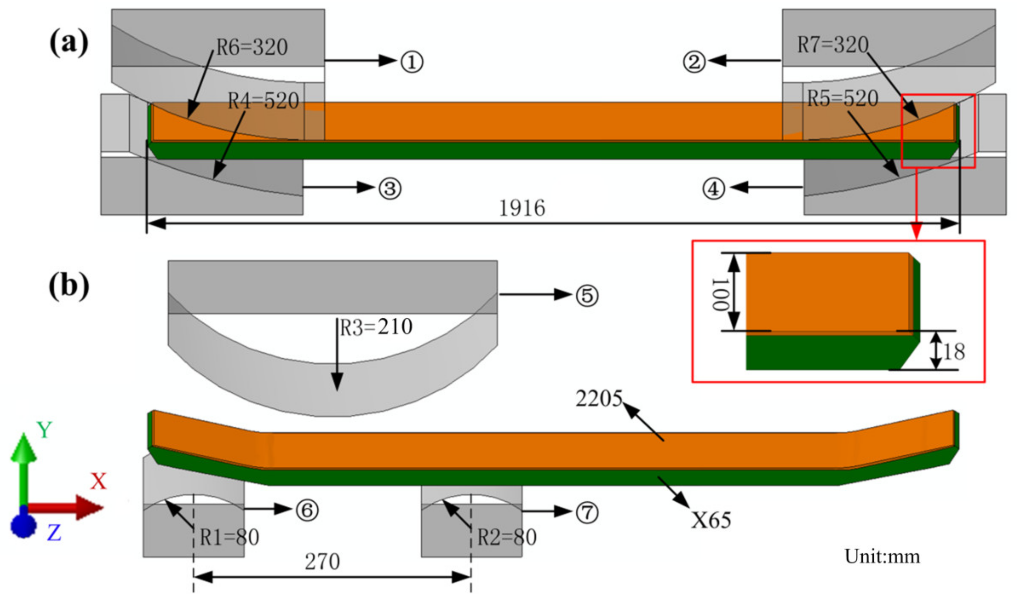
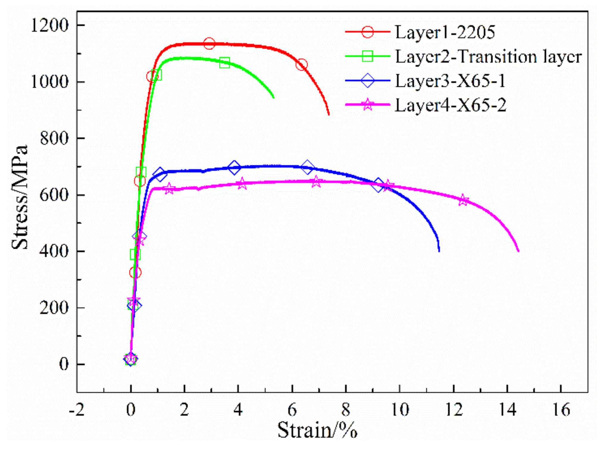
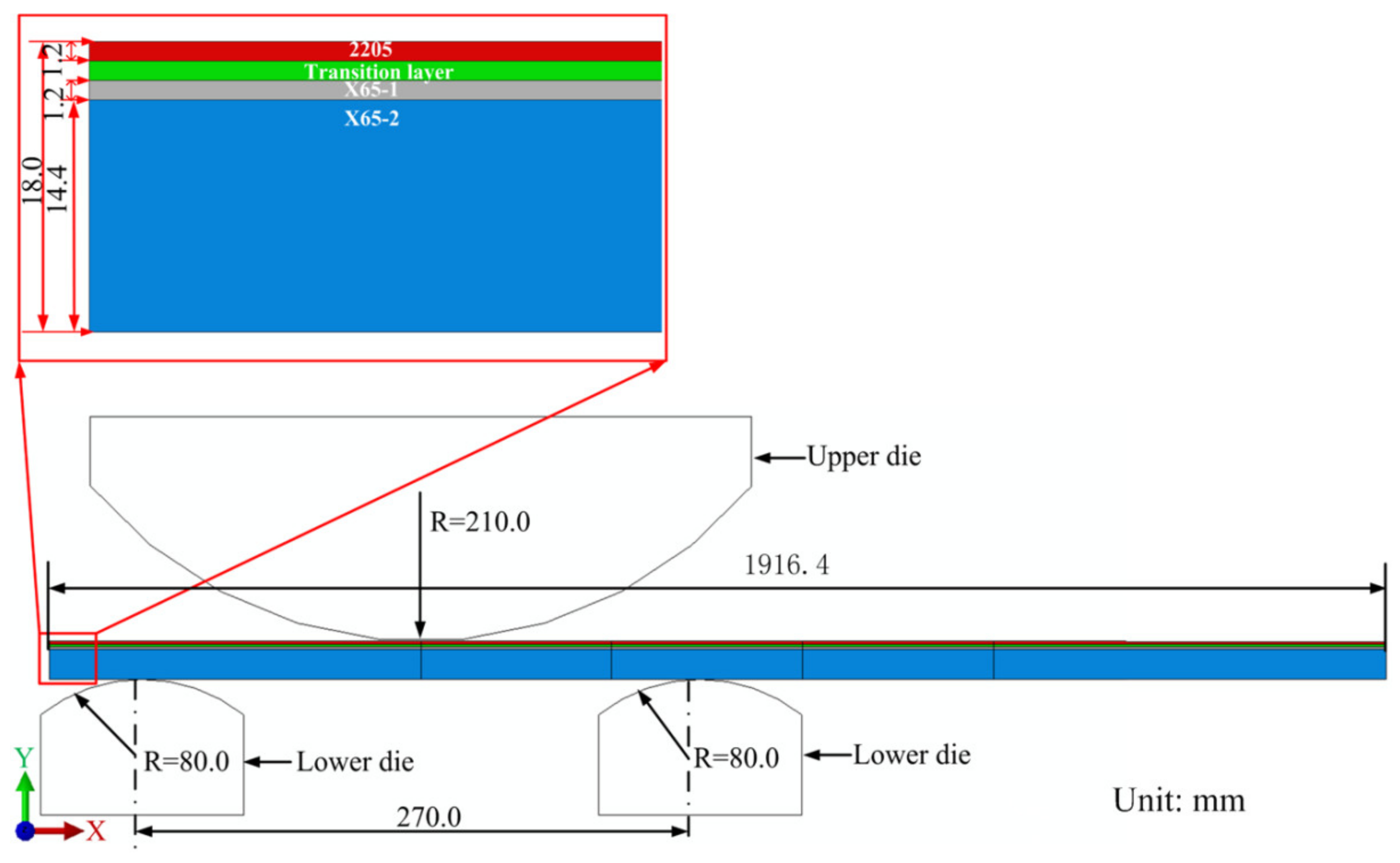
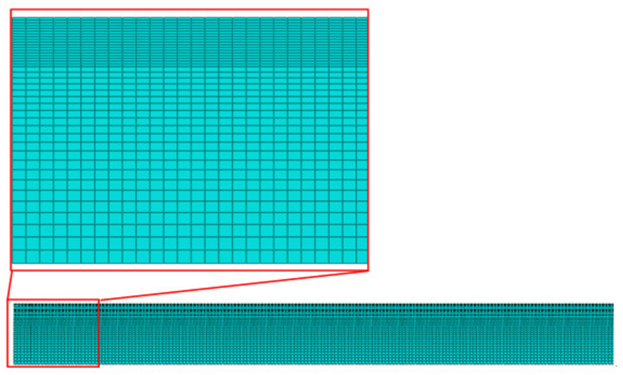
2. Materials and Methods
3. Results and Discussion
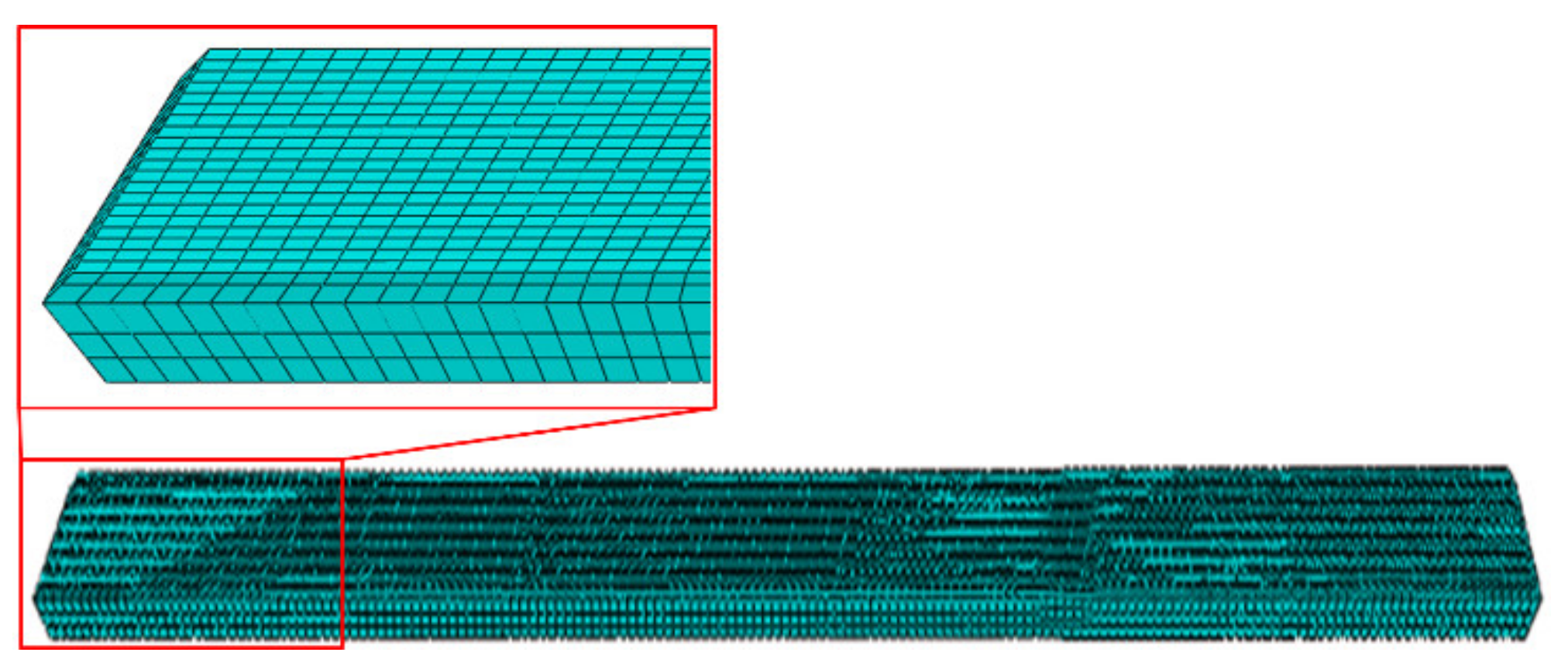
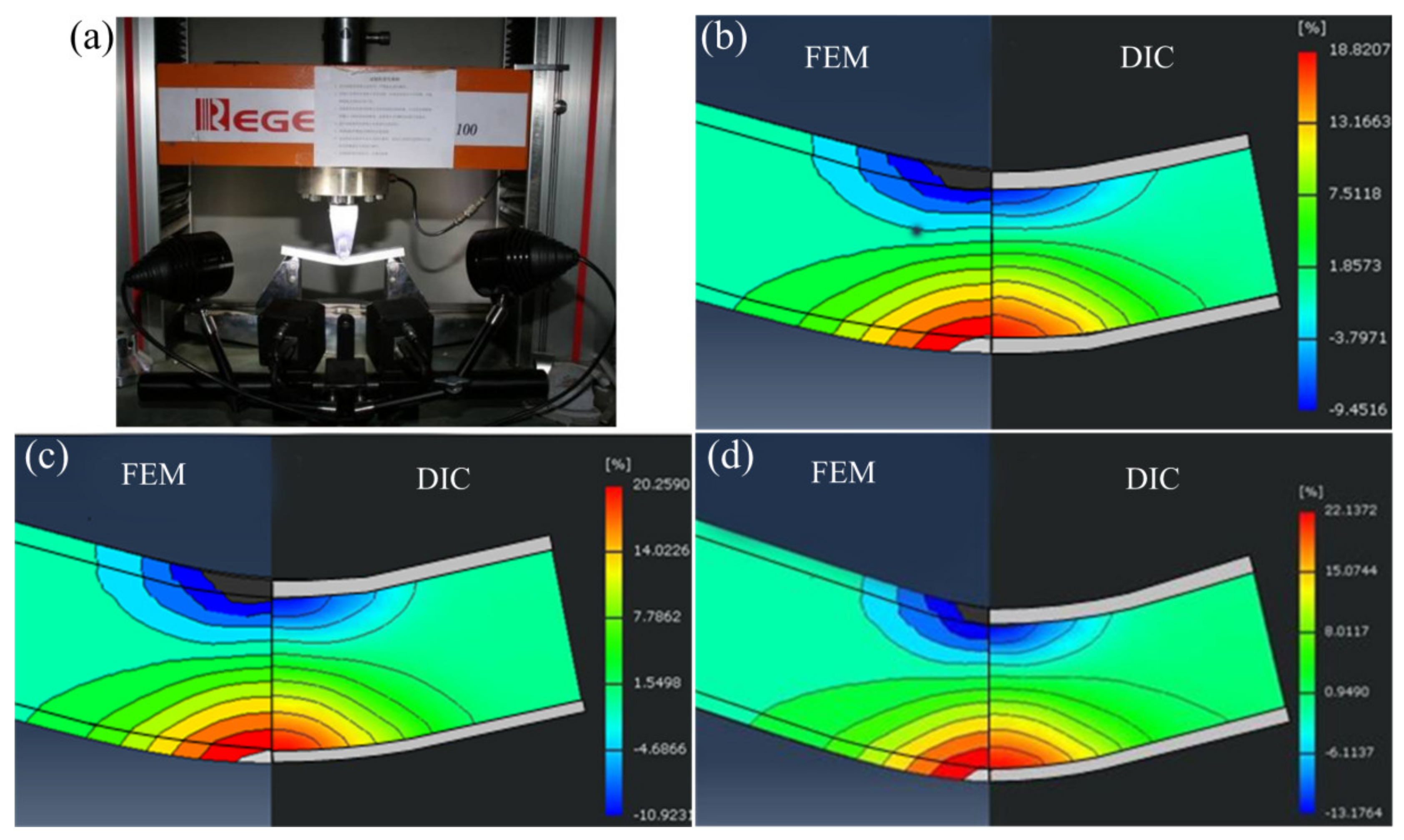
3.1. Confirmation of Finite Element Model
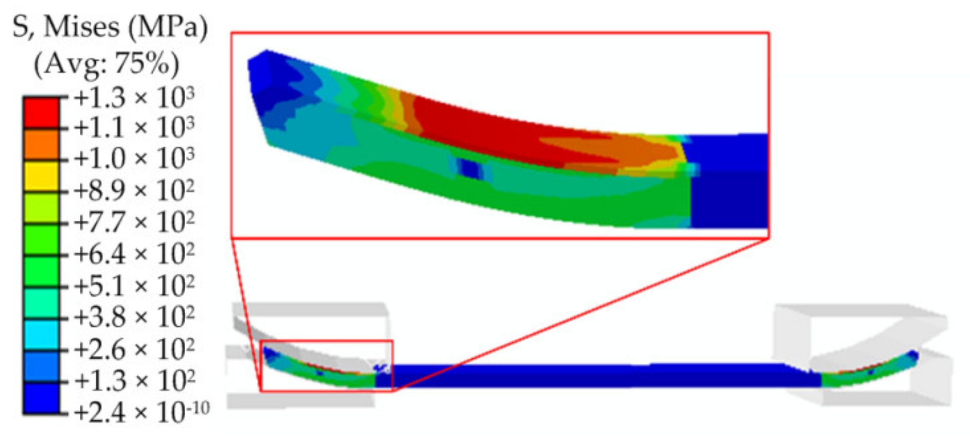
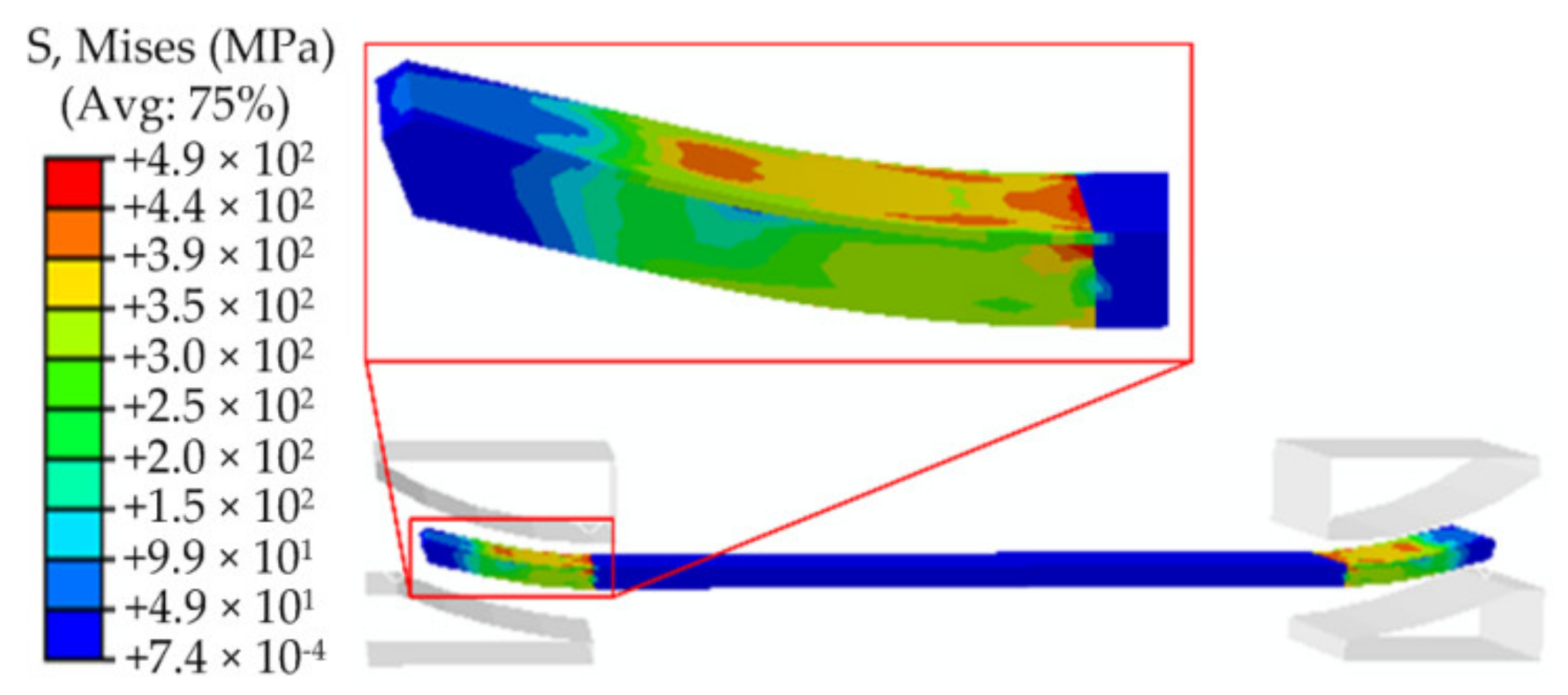
3.2. Pre-Bending
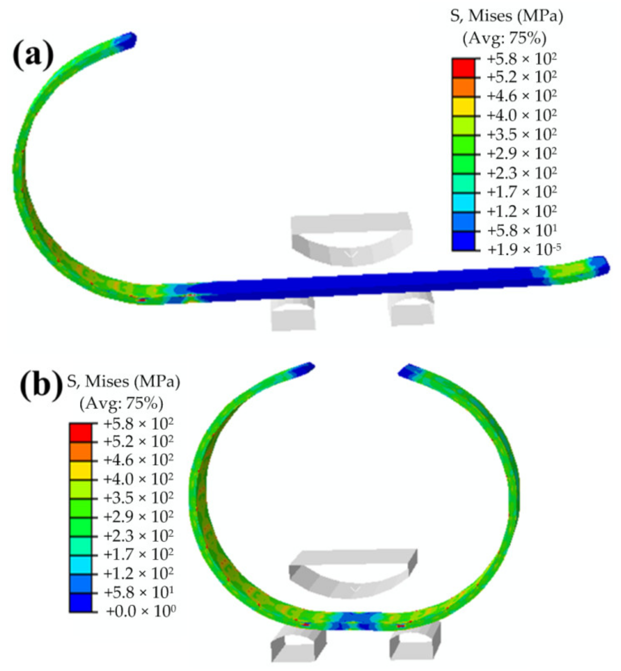
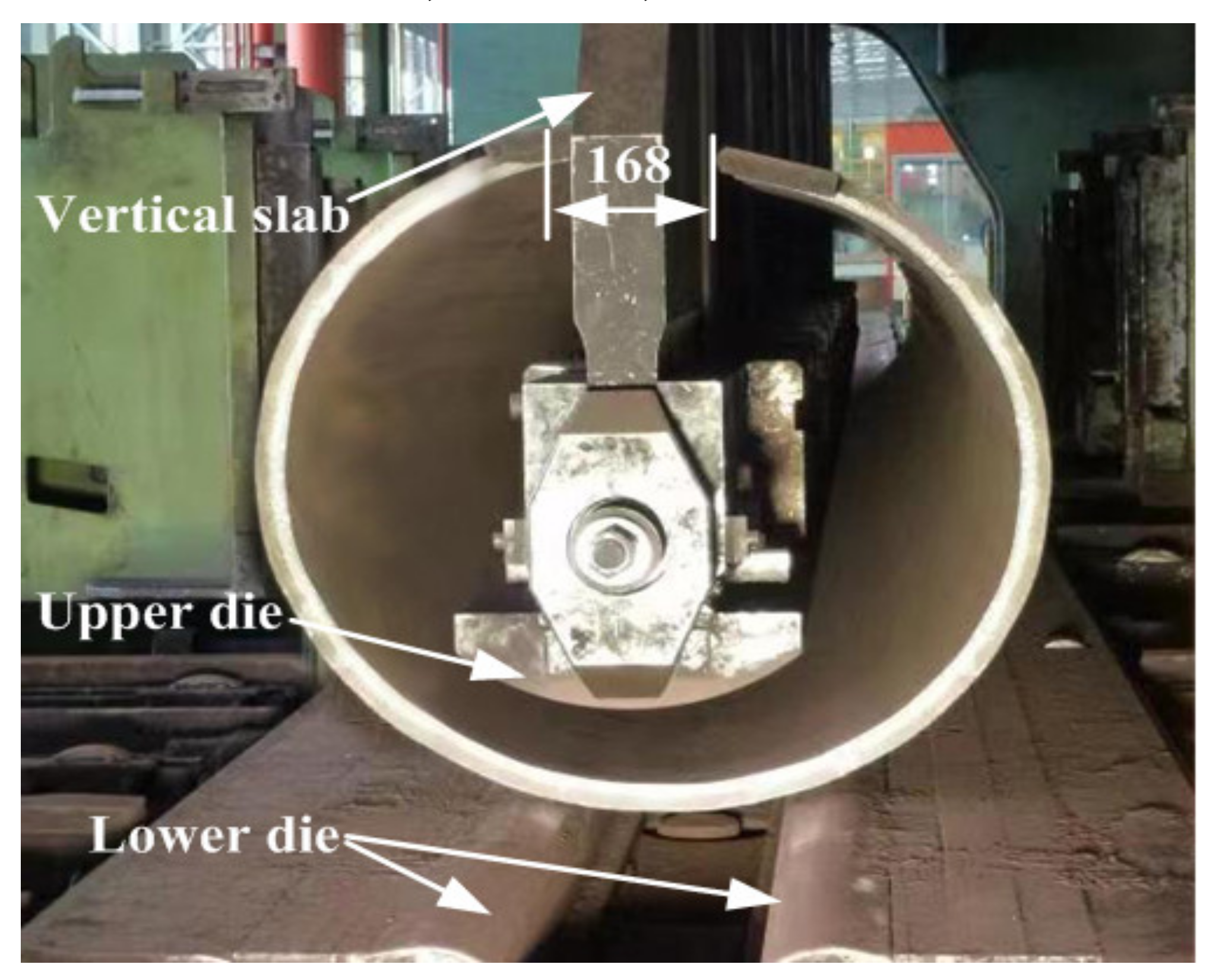
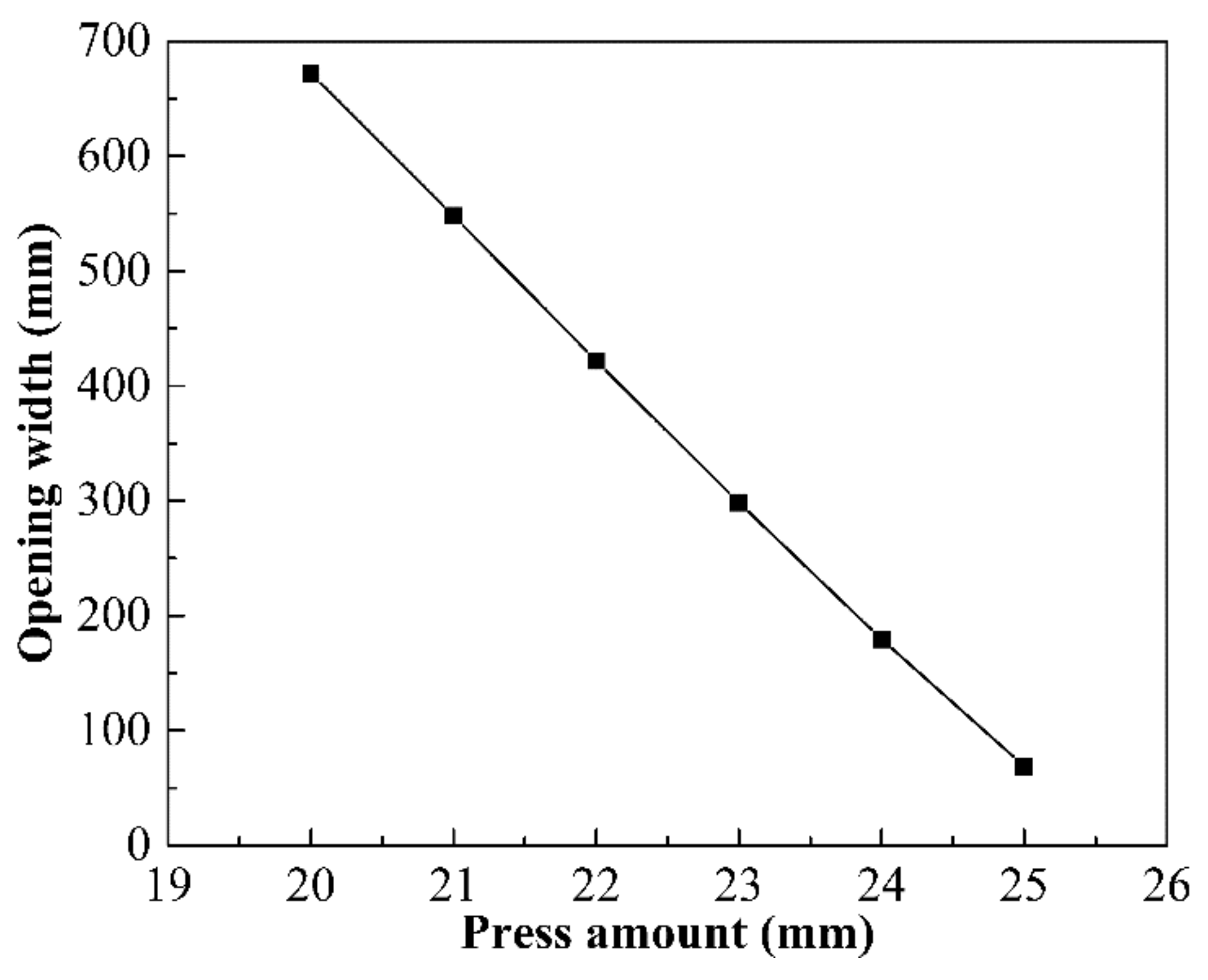
3.3. JCO Forming
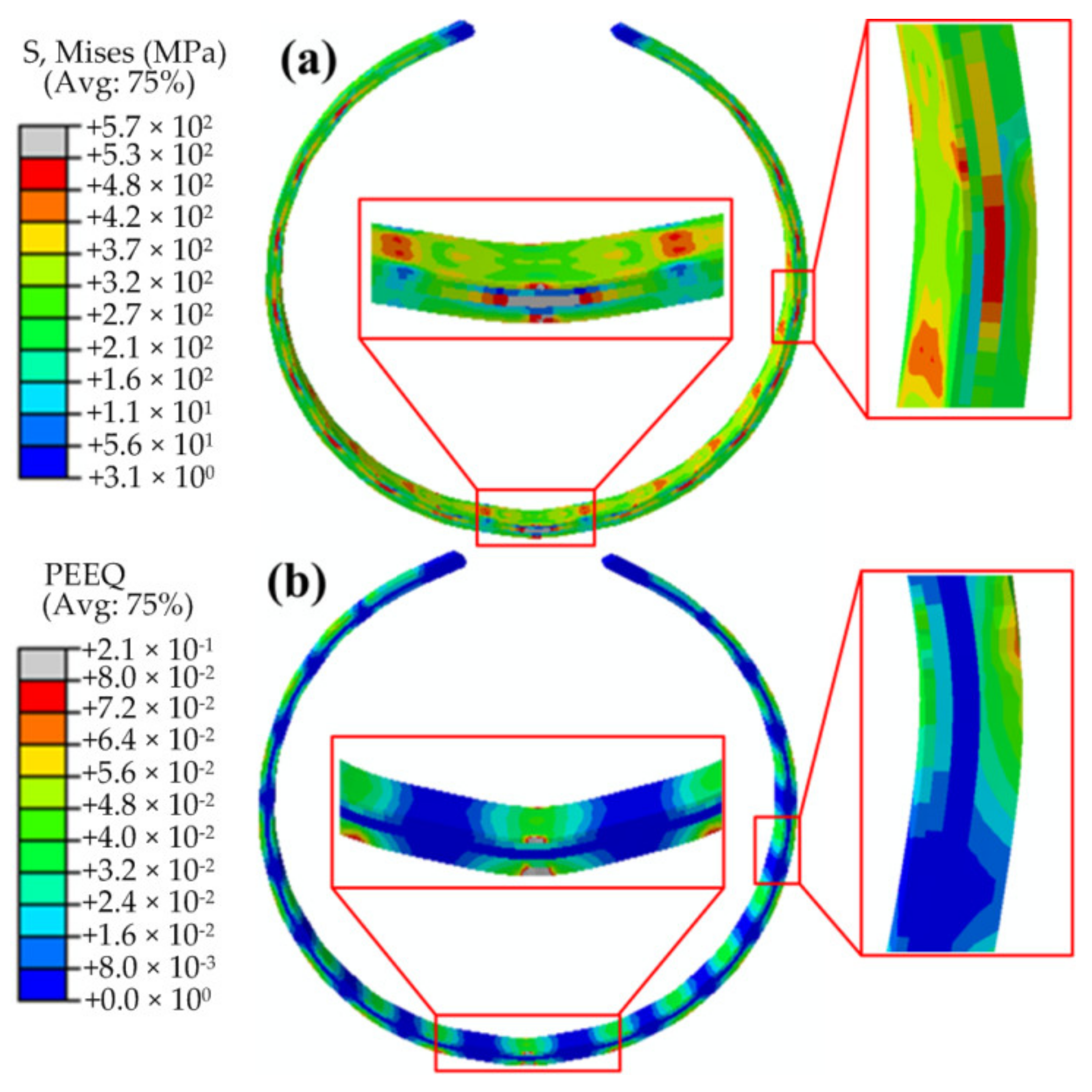
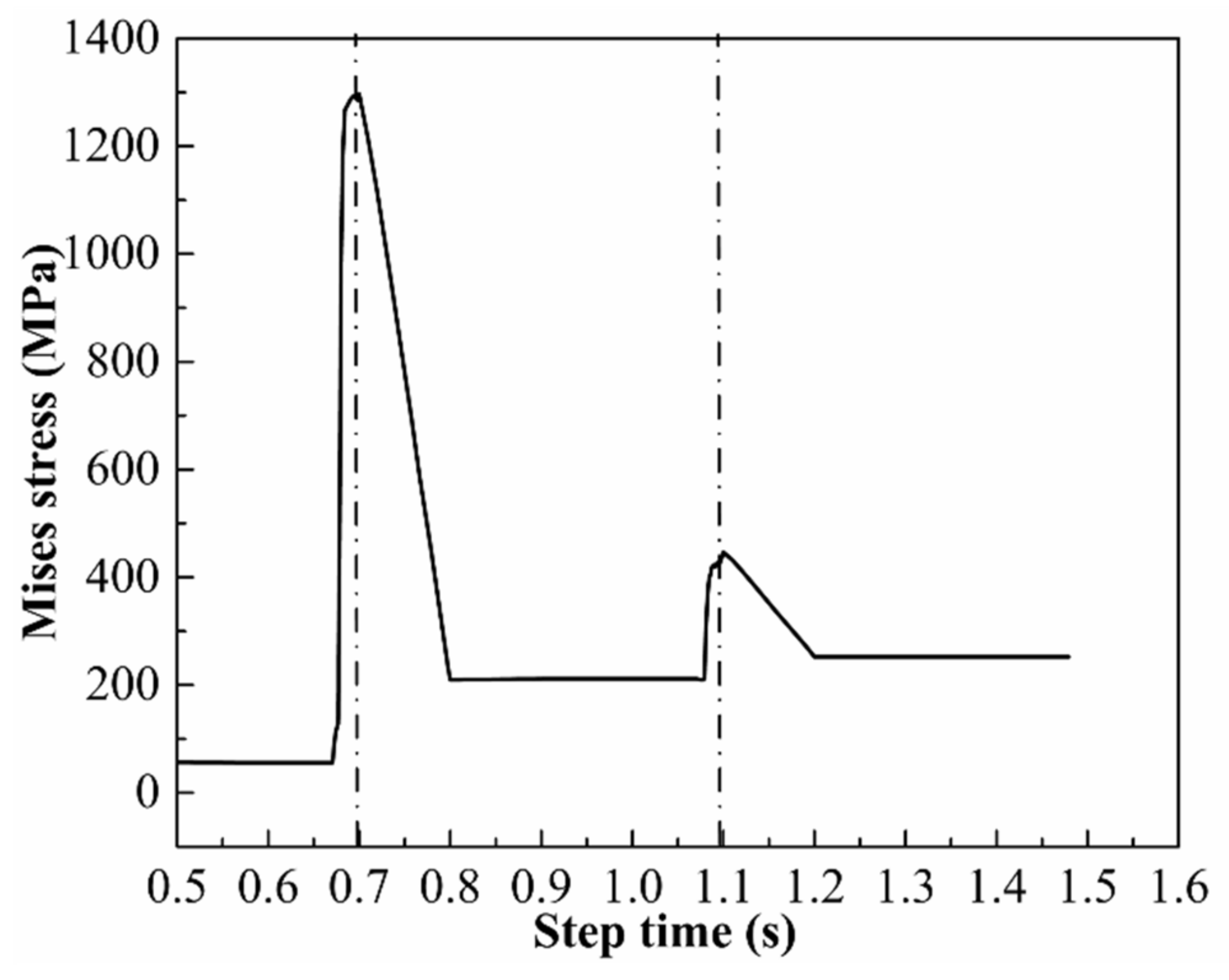
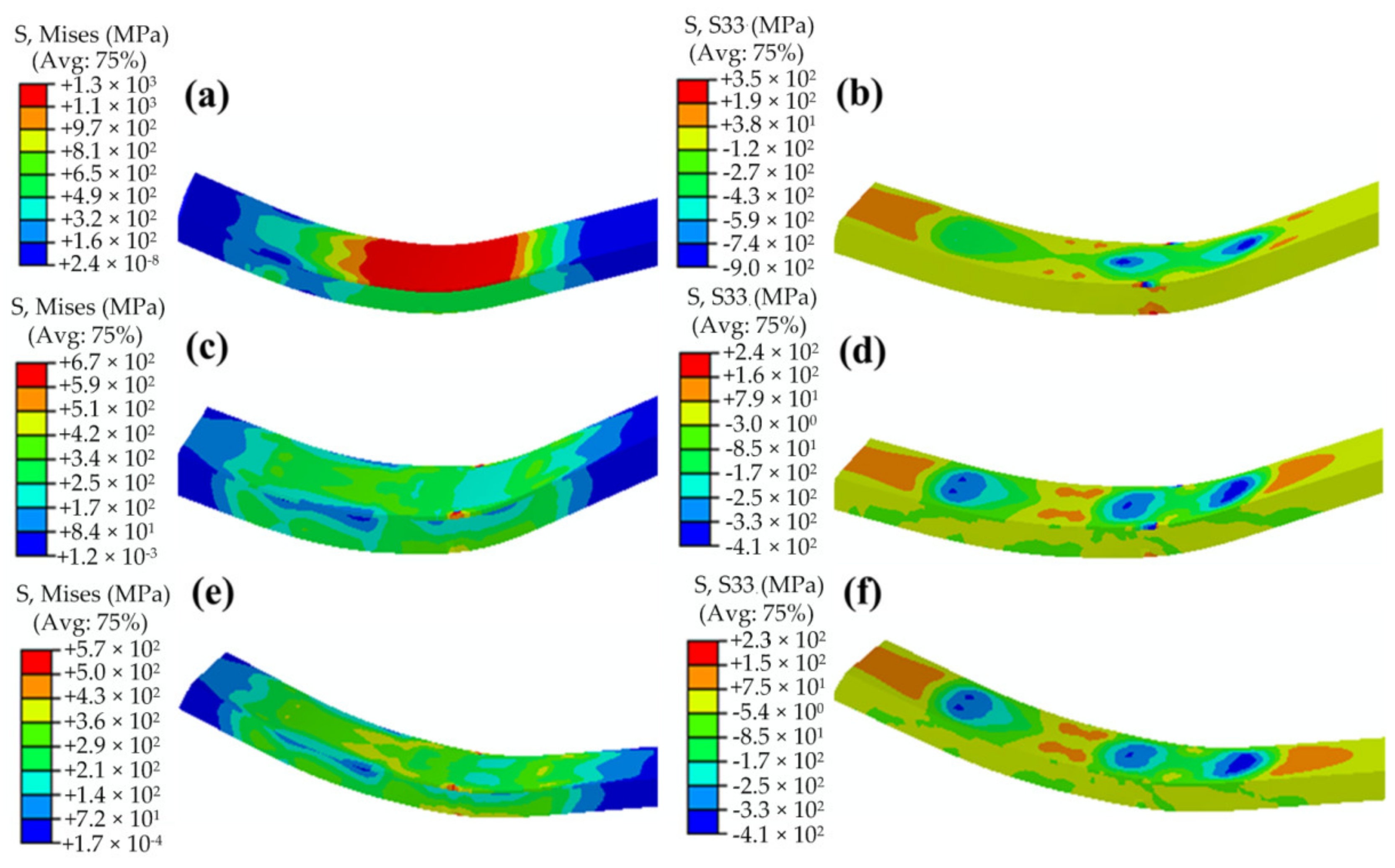
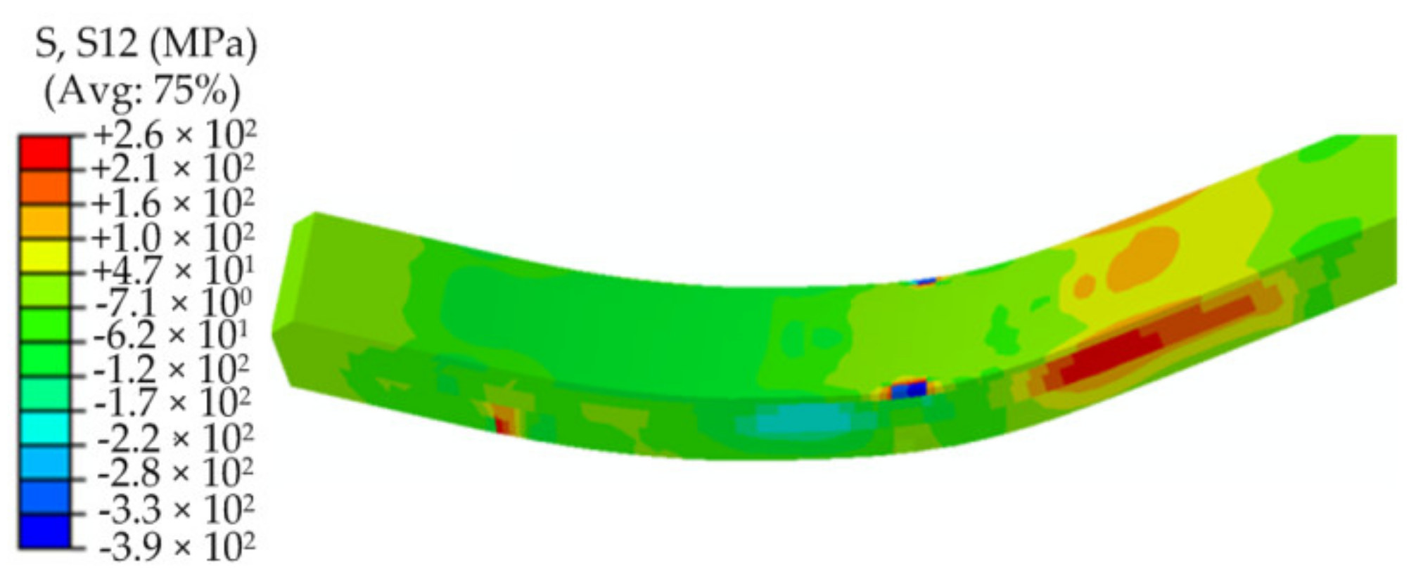
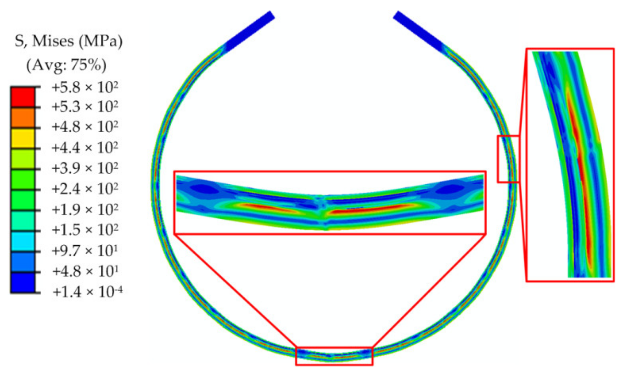
3.4. Analysis of Stress Evolution and Distribution Characteristics of JCO Pipe
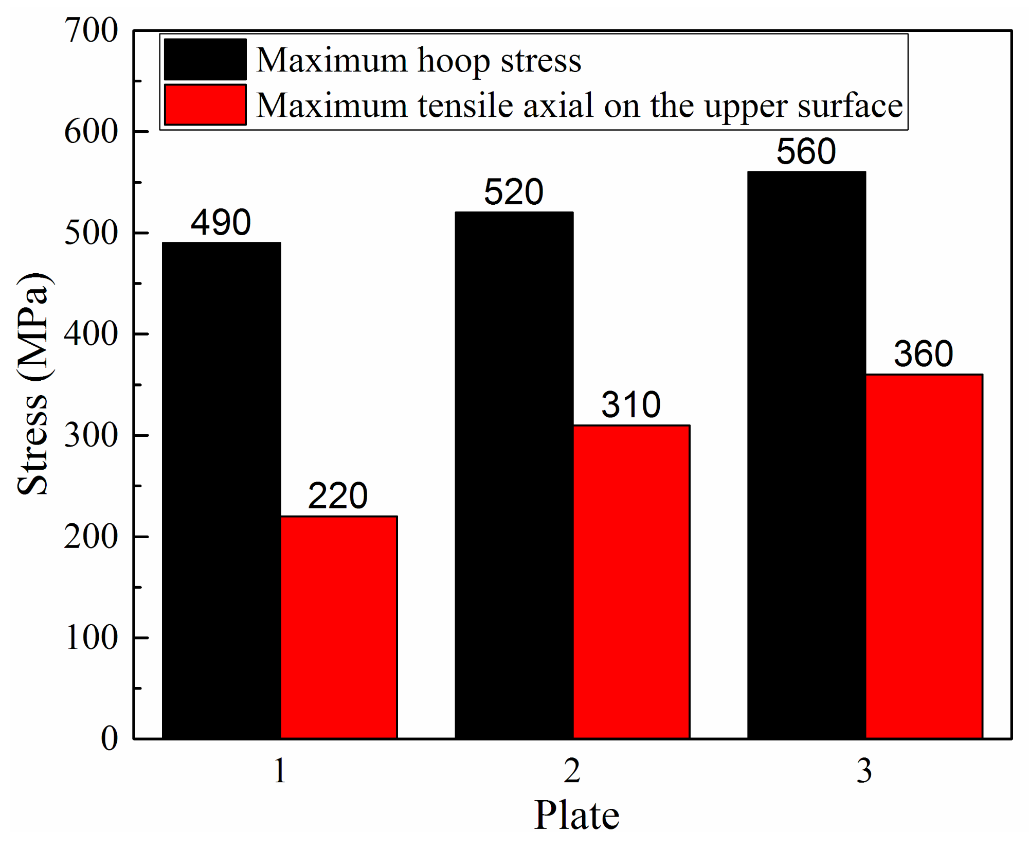
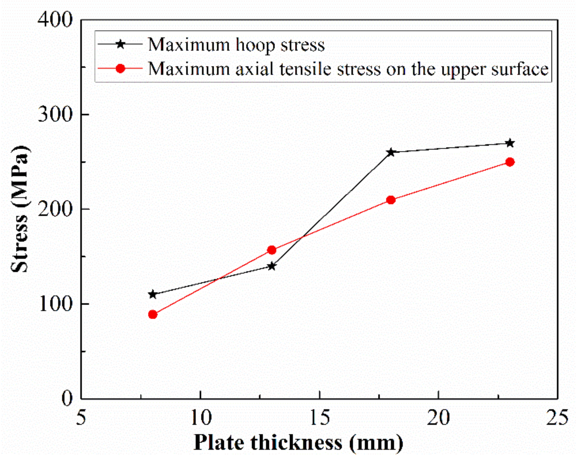
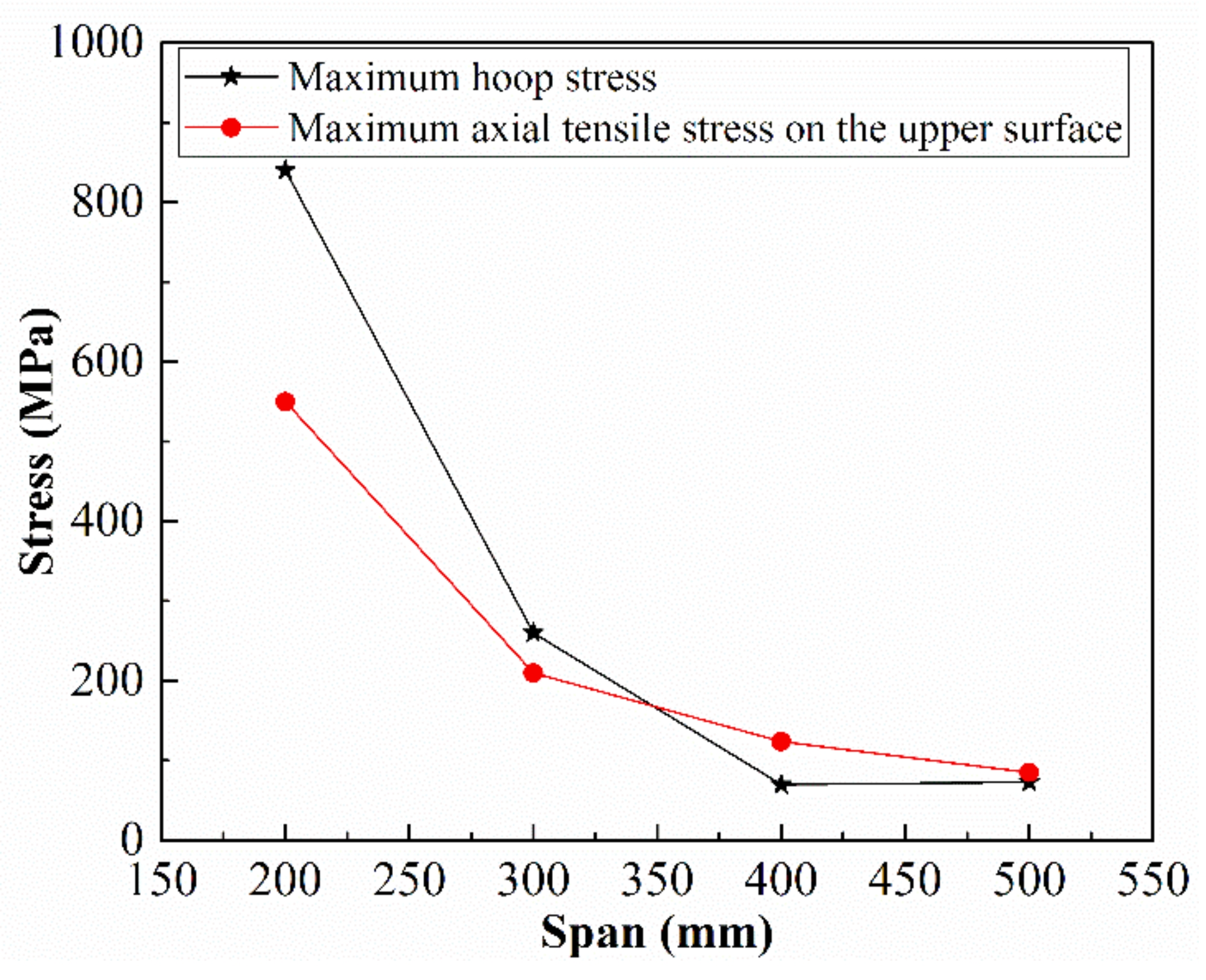
3.5. Influences of Plate Strength, Plate Thickness, and Span on Stresses after JCO Forming of Bimetallic Pipe
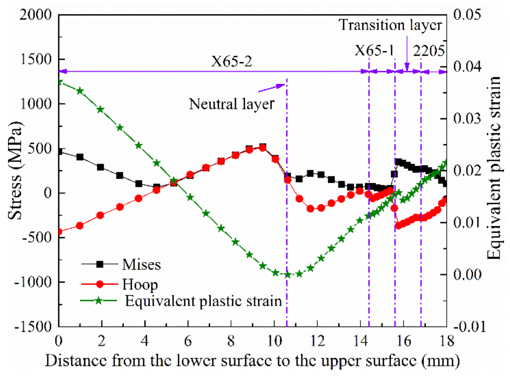
3.6. 2D Modeling and Calculated Results of JCO Pipe
4. Conclusions
- The results of the finite element analysis are in good agreement with those of the DIC experiments.
- The stress and PEEQ distributions of the formed pipe are segmented. The numbers of these segments are the same as the pressing times, and the stresses of each segment are mainly caused by the downward–upward pressing process of the die. The formed pipe billet is composed of alternate circular and straight segments. The opening width of the pipe billet exhibits a linear relationship with the press amount of the JCO upper die, and the appropriate press amount can be obtained by the finite element model, which is confirmed by experiment.
- After the downward pressing process of the die, the stress of the pipe reaches maximum. The equivalent stress of the upper 2205 stainless steel is larger than that of the lower X65 pipe steel, which is related to the larger working-hardening of 2205 than that of X65 during the explosive welding. With the upward pressing of the die, a large elastic-recovery deformation occurs on the plate, and the stress appears to be significantly reduced. As the plate moves forward, the Mises stress and axial stress change little. The maximum shear stress of the pipe in the JCO forming process is much less than the shear strength of the plate, which indicates that the 2205 and X65 interface is well bonded after the JCO forming process.
- The maximum hoop stress and the maximum tensile axial stress on the upper surface increase with increasing plate strength. With the increase in the plate thickness, the maximum tensile axial stress on the upper surface after the JCO forming increases linearly, whereas the hoop stress increases first and then tends to be stable. With the increase in the span, the maximum tensile axial stress on the upper surface of plate reduces significantly, whereas the hoop stress decreases first and then remains unchanged.
- Comparing the results of the 2D and 3D models reveals that the result of the 2D model can only present the stress distribution in the plate thickness direction, and the simulated results in this direction are consistent with those of the 3D model. The neutral layer is closer to the 2205 layer, which has a higher yield strength compared to X65 layer. After unloading, maximum residual Mises stress distribution is found in the middle of the pipe thickness direction, and the hoop stress is compressive on both the upper and lower surfaces.
- A large gradient transition of the stress is present at the interfaces of different materials in bimetallic pipe after JCO process.
Author Contributions
Funding
Conflicts of Interest
References
- Yingsamphancharoen, T.; Srisuwan, N.; Rodchanarowan, A. The electrochemical investigation of the corrosion rates of welded pipe ASTM A106 grade B. Metals 2016, 6, 207. [Google Scholar] [CrossRef]
- Liu, Z.Y.; Dong, C.F.; Li, X.G. Stress corrosion cracking of 2205 duplex stainless steel in H2S–CO2 environment. J. Mater. Sci. 2009, 44, 4228–4234. [Google Scholar] [CrossRef]
- Liu, X.; Zhang, H.; Wang, B.; Xia, M.; Wu, K.; Zheng, Q.; Han, Y. Local Buckling Behavior and Plastic Deformation Capacity of High-Strength Pipe at Strike-Slip Fault Crossing. Metals 2018, 8, 22. [Google Scholar] [CrossRef]
- Wang, X.; Ye, J.D.; Ma, X.; Tian, Q.Q.; Li, X.; Bao, Y. Finite element simulation analysis of multi-stands three-roller cold rolling process for double metal composite seamless steel tube. Appl. Mech. Mater. 2014, 470, 197–204. [Google Scholar] [CrossRef]
- Yang, X.Q. Current Situation, Existing Problems and Development Prospect of Domestic Steel Tube Industry (Part I). Steel Pipe 2008, 37, 12–17. [Google Scholar] [CrossRef]
- Li, Y.F.; Sun, Q. Study and Application of JCOE LSAW Pipe Production Line. Welded Pipe Tube 2004, 27, 48–53. [Google Scholar] [CrossRef]
- Yanfeng, L. R&D of Φ1219 mm X80 LSAW Linepipe for No.2 West-East Gas Transmission Pipeline Project. Steel Pipe 2009, 38, 33–38. [Google Scholar] [CrossRef]
- Zheng, R.; Li, T.J. Production and Development of China’s Pipeline Steel. Heavy Mach. Technol. 2003, 4, 45–49. [Google Scholar] [CrossRef]
- Barnes, P.; Hejazi, R.; Karrech, A. Instability of mechanically lined pipelines under large deformation. Finite Elem. Anal. Des. 2018, 146, 62–69. [Google Scholar] [CrossRef]
- Li, R.; Eyckens, P.; Gawad, J.; Poucke, M.; Cooreman, S.; Bael, A. Advanced plasticity modeling for ultra-low-cycle-fatigue simulation of steel pipe. Metals 2017, 7, 140. [Google Scholar] [CrossRef]
- Kim, N.; Kang, B.; Lee, S. Prediction and design of edge shape of initial strip for thick tube roll forming using finite element method. J. Mater. Process. Technol. 2003, 142, 479–486. [Google Scholar] [CrossRef]
- Jiang, J.; Li, D.; Peng, Y.; Li, J. Research on strip deformation in the cage roll-forming process of ERW round pipes. J. Mater. Process. Technol. 2009, 209, 4850–4856. [Google Scholar] [CrossRef]
- Ren, Q.; Zou, T.; Li, D.; Tang, D.; Peng, Y. Numerical study on the X80 UoePipe forming process. J. Mater. Process. Technol. 2015, 215, 264–277. [Google Scholar] [CrossRef]
- Gao, Y.; Li, Q.; Xiao, L. Numerical Simulation of JCO/JCOE Pipe Forming. In Proceedings of the World Congress on Computer Science and Information Engineering, Los Angeles, CA, USA, 31 March–2 April 2009; pp. 233–237. [Google Scholar] [CrossRef]
- Luo, J.; Xue, Y.; Chen, K.; Shang, Y.; Zhang, C. Integrated simulation and experimental test of the residual stress field for large-sized straight welded pipe processed with JCOE Technology. Int. J. Steel Struct. 2017, 17, 65–272. [Google Scholar] [CrossRef]
- Ren, Y.; Paradowska, A.; Eren, E.; Wang, B. Challenges of Measuring Residual Stresses in Large Girth Welded Pipe Spools by Neutron Diffraction. In Proceedings of the International Conference on Residual Stresses, Sydney, Australia, 3–7 July 2016; pp. 575–580. [Google Scholar] [CrossRef]
- Chen, W.; Boven, G.V.; Rogge, R. The role of residual stress in neutral PH stress corrosion cracking of pipeline steels—Part II: Crack dormancy. Acta Mater. 2007, 55, 43–53. [Google Scholar] [CrossRef]
- Hino, R.; Goto, Y.; Yoshida, F. Springback of sheet metal laminates in draw-bending. J. Mater. Process. Technol. 2003, 139, 341–347. [Google Scholar] [CrossRef]
- Ling, Y.E.; Lee, H.P.; Cheok, H.P. Finite Element Nnalysis of Springback in L-bending of Sheet Metal. J. Mater. Process. Technol. 2005, 168, 296–302. [Google Scholar] [CrossRef]
- Gao, Y.; Li, Q.; Fan, L.; Wang, X. Applications of Finite Element Method in Large-diameter Longitudinal Welded Pipe. In Proceedings of the International Conference on Measuring Technology and Mechatronics Automation, Zhangjiajie, China, 11–12 April 2009; pp. 22–25. [Google Scholar] [CrossRef]
- Zhang, L.J.; Pei, Q.; Zhang, J.X.; Bi, Z.Y.; Li, P.C. Study on the microstructure and mechanical properties of explosive welded 2205/X65 bimetallic sheet. Mater. Des. 2014, 64, 62–476. [Google Scholar] [CrossRef]
- Gou, N.N.; Zhang, L.J.; Zhang, J.X. Increased quality and welding efficiency of laser butt welding of 2205/X65 bimetallic sheets with a lagging MIG arc. J. Mater. Process. Technol. 2018, 251, 83–92. [Google Scholar] [CrossRef]
- Dong, Z.Q.; Zhang, J.X. Three-dimensional finite element analysis of residual stresses in circumferential welds of 2205/X65 bimetallic pipe. Int. J. Adv. Manuf. Technol. 2018, 96, 2841–2851. [Google Scholar] [CrossRef]
- Tsai, W.T.; Chen, M.S. Stress corrosion cracking behavior of 2205 duplex stainless steel in concentrated NaCl solution. Corros. Sci. 2000, 42, 545–559. [Google Scholar] [CrossRef]
- Fukuda, N.; Hagiwara, N.; Masuda, T. Effect of prestrain on tensile and fracture toughness properties of line pipes. J. Offshore Mech. Arct. Eng. 2005, 127, 263–268. [Google Scholar] [CrossRef]
- Nixon, M.E.; Lebensohn, R.A.; Cazacu, O.; Liu, C. Experimental and finite-element analysis of the anisotropic response of high-purity α-titanium in bending. Acta Mater. 2010, 58, 5759–5767. [Google Scholar] [CrossRef]


| E/GPa | μ | ρ/tonne/mm3 | |
|---|---|---|---|
| X65 | 210 | 0.3 | 7.85 × 10⁻⁹ |
| 2205 | 210 | 0.3 | 7.80 × 10⁻⁹ |
| C | Si | Cr | Mn | Ni | Cu | Mo | V | P | S | Fe | |
|---|---|---|---|---|---|---|---|---|---|---|---|
| X65 | 0.053 | 0.33 | 0.07 | 1.18 | 0.16 | 0.14 | 0.06 | 0.031 | 0.016 | ≤0.005 | Balance |
| 2205 | 0.021 | 0.56 | 22.59 | 1.13 | 5.29 | - | 3.45 | - | 0.018 | 0.001 | Balance |
| Press Amount/mm | Springback/mm | Bending Angle/° | ||||
|---|---|---|---|---|---|---|
| DIC | FEM | Relative Error % | DIC | FEM | Relative Error % | |
| 20 | 1.72 | 1.65 | 4.1 | 26.83 | 28.1 | 4.5 |
| 21 | 1.73 | 1.66 | 4.0 | 28.3 | 29.6 | 4.4 |
| 22 | 1.74 | 1.67 | 4.0 | 29.69 | 31.1 | 4.5 |
| Plate | Layer | Yield Strength/MPa |
|---|---|---|
| Plate 1 | X65 | 508 |
| 2205 | 530 | |
| Plate 2 | X65 | 534 |
| 2205 | 774 | |
| Plate 3 | X65 | 560 |
| 2205 | 1018 |
© 2020 by the authors. Licensee MDPI, Basel, Switzerland. This article is an open access article distributed under the terms and conditions of the Creative Commons Attribution (CC BY) license (http://creativecommons.org/licenses/by/4.0/).
Share and Cite
Dong, Z.; Xu, Z.; Wang, W.; Bi, Z.; Zhang, J. Numerical Simulation and Experimental Confirmation of a Bimetallic Pipe Forming Process. Materials 2020, 13, 3561. https://doi.org/10.3390/ma13163561
Dong Z, Xu Z, Wang W, Bi Z, Zhang J. Numerical Simulation and Experimental Confirmation of a Bimetallic Pipe Forming Process. Materials. 2020; 13(16):3561. https://doi.org/10.3390/ma13163561
Chicago/Turabian StyleDong, Zhiqiang, Zhenzhen Xu, Wenke Wang, Zongyue Bi, and Jianxun Zhang. 2020. "Numerical Simulation and Experimental Confirmation of a Bimetallic Pipe Forming Process" Materials 13, no. 16: 3561. https://doi.org/10.3390/ma13163561
APA StyleDong, Z., Xu, Z., Wang, W., Bi, Z., & Zhang, J. (2020). Numerical Simulation and Experimental Confirmation of a Bimetallic Pipe Forming Process. Materials, 13(16), 3561. https://doi.org/10.3390/ma13163561