Abstract
The aim of this work was to monitor the corrosion rate of the Mg72Zn24Ca4 and Zn87Mg9Ca4 alloys. The purity of the alloying elements was 99.9%. The melt process was carried out in an induction furnace. The melting process took place under the cover of an inert gas (argon). The copper form was flooded by liquid alloy. Then, in order to obtain ribbons, the cast alloy, in rod shape, was re-melted on the melt spinning machine. The corrosion resistance of both alloys has been determined on the basis of the following experiments: measurements of the evolution of OCP (open circuit potential), LSV (linear sweep voltamperometry) and EIS (electrochemical impedance spectroscopy). All corrosion tests were carried out in Ringer’s solution at 37 °C and pH 7.2. The corrosion tests have revealed that the zinc alloy, Zn87Mg9Ca4, exhibits significantly higher corrosion resistance in the Ringer solution compared to the magnesium alloy, Mg72Zn24Ca4. Moreover, it has been shown that the cathodic reaction proceeds faster on the surface of ribbons. EIS measurements show that the dissolution of Mg alloy proceeds with two steps: transfer of Mg2+ ions to the Ringer solution and then the formation of the corrosion products, which are deposited on the surface of magnesium alloy. It has been revealed, too, that for both bulk materials, diffusion of chloride ions through the corrosion product’s layer takes place.
1. Introduction
Biodegradable metals in recent years have attracted considerable attention as potential orthopedic implants. Mg and its alloys [,,,,] including Mg-Ca [], Mg-RE [,], Mg-Sr [], Mg-Zn [,] and Mg-based bulk metallic glasses (BMGs) [,] are considered biodegradable metallic materials.
Due to very good biodegradability, biocompatibility and non-toxicity, magnesium and its alloys are widely used in the biomedical sector []. Large amounts of Mg2+ are present in the human body. These ions participate in many metabolic reactions, biological mechanisms, and their excess is easily excreted via urine [].
The human body has an inborn tolerance for the absorption of magnesium, zinc and calcium. The daily intake ordered for these elements is 1000 mg day−1 of Ca [], 420 mg day−1 of Mg [], 10 mg day−1 of Zn []. In addition, the presence of these ions in the human body is associated with antibacterial action against bacteria, such as: Escherichia coli, Pseudomonas aeruginosa, Staphylococcus aureus, and against the occurrence of anaerobes in the oral cavity [,].
Magnesium alloys have a complex microstructure, which consists of matrix, intermetallic phases, eutectic, and precipitates. Moreover, the alloying elements are not uniformly distributed within the magnesium matrix. Therefore, the corrosion of magnesium alloys is not uniform. The corrosion process usually starts at the interface of matrix/intermetallic phases. The intermetallic phases can behave as cathodic or anodic places depending on their chemical composition. Type, size and distribution of precipitates within the magnesium matrix have a significant influence on the corrosion resistance of Mg alloys [,,,]. It was found that good corrosion resistance of Mg alloys can be achieved when structural uniformity is present. The amorphous magnesium-based alloys have a lower corrosion rate in comparison to crystalline specimens, which have precipitates in their microstructure [,]. The amorphous structure ensures greater ability of passivation and lower susceptibility to local corrosion of magnesium-based alloys.
Recently, in the literature [,,,,,,], there is considerable interest in zinc and its alloys as a material for orthopedic implants and devices for cardiovascular interventional. The interest in this material is related, on the one hand, to their biodegradability and, on the other hand, to very good biocompatibility. Additionally, it should be noted that zinc plays a key role in the human body. It takes part in the metabolism of the human body, for example in the composition of essential enzymes for the synthesis of proteins and transcription factors [,,]. It should be noted that the released zinc from the implants during its dissolution is non-toxic and does not cause side effects. The tests performed on mice showed good zinc biocompatibility in the abdominal aorta and the femur of the animal. It causes strong adherence to the wire of healthy arterial tissue [,] and the formation of new bone around the pins [,]. Additionally, the electrochemical potential of zinc is located between the value of the potentials measured for magnesium and iron. At the same time, the biodegradable use of metal implants is still being questioned. This is especially the case with implants made of alloys based on magnesium or iron [,,,,,]. On the one hand, it is related to the too fast degradation of implants based on magnesium alloys, caused by rapid corrosion, preventing effective bone fusion, and on the other hand, too slow degradation of implants based on iron alloys, resulting in the appearance of permanent implants [,,]. Despite the great advantages of zinc, the use of pure zinc as a material for biodegradable implants is limited due to low mechanical properties such as strength, plasticity and hardness.
Calcium is a major component in human bone and is essential in chemical signaling with cells [,]. In addition, magnesium is necessary to incorporate calcium into the bone [,], which might be expected to be beneficial to the bone healing with the co-releasing of Mg and Ca ions. Calcium is also beneficial to the grain refinement of magnesium alloys. The solubility limit of Ca in Mg is 1.34 wt % [,]. The Mg-Ca alloys are mainly composed of α (Mg) phase and Mg2Ca phase [,]. With increasing Ca content, more and coarser Mg2Ca phase precipitates along grain boundaries, weakening both the mechanical property and corrosion resistance of as-cast Mg-Ca alloy [,,].
In this work, calcium was selected as the alloying component to develop ternary magnesium–zinc–calcium and zinc–magnesium–calcium alloys. The corrosion resistance of both alloys in the Ringer solution has been investigated.
2. Materials and Methods
In order to obtain the Mg72Zn24Ca4 and Zn87Mg9Ca4 alloys, alloying elements with a purity of 99.99% were used. Then, the melt was carried out in a resistance furnace under argon as an inert gas. Afterwards, the Mg72Zn24Ca4 and Zn87Mg9Ca4 alloys were cast into the steel metal mold to obtain a cylinder sample with the following dimensions: diameter = 20 mm and height = 50 mm. Final dimensions of samples for further testing after machining: diameter = 10 mm and height = 50 mm. Then, in order to obtain ribbons, the cast alloy, in rod shape, was re-melted on the melt spinning machine. The average thickness of the ribbons, produced in the melt spinning process, was approximately between 100–150 µm. The rotational speed of the wheel during the melt spinning of ribbons was 35 m/min. Then, the corrosion resistance of bulk Mg72Zn24Ca4 and Zn87Mg9Ca4 alloys has been determined.
The corrosion tests have been performed in the Ringer solution at 37 °C. The chemical composition of the Ringer solution is given in Table 1.

Table 1.
The chemical composition of Ringer’s solution.
The bulk material of Mg72Zn24Ca4 and Zn87Mg9Ca4 alloys used for corrosion tests were ground on abrasive papers with gradations from 1200 to 4000. After each polishing step, the samples were cleaned for 5 min in ethanol using ultrasound.
In order to determine the corrosion resistance of the Mg72Zn24Ca4 and Zn87Mg9Ca4 alloys evolution of corrosion potential versus time (OCP—open circuit potential), potentiodynamic polarization curves (LSV—linear sweep voltamperometry) were measured. The potential scan rate for linear sweep voltamperometry was 1 mV/s. Afterwards, electrochemical impedance spectroscopy (EIS) was performed. EIS spectra were measured at the OCP, the amplitude of the perturbation signal was 10 mV, and the frequency range was from 100 kHz to 0.003 Hz. Experimental EIS data were analyzed by being fit to an equivalent electrical circuit model by using Zview software. In order to obtain the steady state, the specimens were immersed in the Ringer solution for 24 h and then the EIS spectra were measured for bulk material samples (before melt spinning process). All electrochemical measurements were performed in the aerated Ringer’s solution at 37 °C. The corrosion tests were performed by using the AUTOLAB PGSTAT 128 potentiostat.
The microstructure of Mg72Zn24Ca4 and Zn87Mg9Ca4 alloys were investigated by using a scanning electron microscopy SEM/EDS (JEOL JSM-5500LV, Tokyo, Japan). In order to determine the intermetallic phases present in these alloys, XRD measurements were performed using Philips PW 1840 X-ray diffractometer (Cambridge, UK) with Co K α radiation (λ = 1.78896A) with the X’Pert system, equipped with the ATC-3 texture goniometer using Philips APD company programs and ICDD (the International Centre For Diffraction Data) crystallographic database.
3. Results
Figure 1 depicts SEM/EDS images for Mg72Zn24Ca4 (a) and for Zn87Mg9Ca4 (b) alloys, respectively. The chemical composition of individual phases was determined by EDS (secondary electron mode) analysis and is given in Table 2 and Table 3.

Figure 1.
SEM/EDS images revealed after mechanical polishing for Mg72Zn24Ca4 (a) and Zn87Mg9Ca4 (b) alloys, respectively.
Table 2.
The content of individual alloy components in a given area of Mg72Zn24Ca4 alloy.
Table 3.
The content of individual alloy components in a given area of Zn87Mg9Ca4 alloy.
As shown in Figure 1, the microstructure of the as-cast alloy consists of the α-Mg matrix, particle phases, and skeleton phases [,,,]. The phases occurring in the tested alloys are Mg39Zn for the Mg72Zn24Ca4 alloy (Figure 1a) and Mg2Zn11 for the Zn87Mg9Ca4 alloy (Figure 1b). Microstructure consists of primary dendrites of Zn (white areas) and Zn + Mg2Zn11 eutectic mixture (dark areas) in the case of Zn alloy, Figure 1b. It has been shown, that the volume fraction of eutectic mixture is increased with higher content of Zn.
Figure 2 and Figure 3 depicts the microstructure image for the Mg72Zn24Ca4 bulk and Zn87Mg9Ca4 material sample—before the melt spinning process.
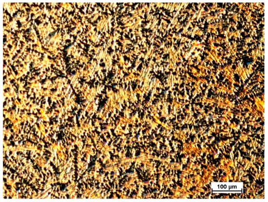
Figure 2.
Light microscope image of microstructure revealed after etching in 2% nital solution for Mg72Zn24Ca4 bulk material sample—before the melt spinning process.

Figure 3.
Light microscope image of microstructure revealed after etching in 2% nital solution for Zn87Mg9Ca4 bulk material sample—before the melt spinning process.
The XRD results for Mg72Zn24Ca4 alloy ingot samples (before the melt spinning process) and ribbon (after the melt spinning process) are presented in Figure 4.
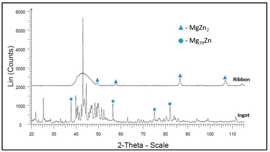
Figure 4.
X-ray diffraction results for Mg72Zn24Ca4 alloy samples.
The XRD results for Zn87Mg9Ca4 alloy ingot samples (before the melt spinning process) and ribbon (after the melt spinning process) are presented in Figure 5.

Figure 5.
X-ray diffraction results for Zn87Mg9Ca4 alloy samples.
X-ray diffraction (XRD) analysis was carried out to verify the glassy nature of the ribbons after the melt spinning process (Figure 4 and Figure 5). Figure 4 shows the results of XRD tests for both the ribbon and the ingot of the Mg72Zn24Ca4 alloy. The ribbon has an amorphous structure with a small amount of the MgZn2 intermetallic phase, while the ingot is characterized by a crystalline structure [,]. Figure 5 presents MgZn and CaZn13 phase for the ribbon of Zn87Mg9Ca4 alloy after the melt spinning process. This fact addresses the large fragmentation of the structure that followed the melt spinning process. It indicates that it is not an amorphous structure as in the case of the Mg72Zn24Ca4 alloy ribbon. In addition, the Zn87Mg9Ca4 alloy strip shown in Figure 5 has more phase spots (peaks of MgZn and CaZn13 phase) after X-ray diffraction compared to the Mg72Zn24Ca4 alloy ribbon shown in Figure 4.
Figure 6 shows the evolution of open circuit potential (OCP) for Mg72Zn24Ca4 and Zn87Mg9Ca4 specimens in the Ringer solution. After three hours of immersion of specimens in the Ringer solution, the following values of OCP were measured: −1.40 V and −1.03 V for Mg72Zn24Ca4 and Zn87Mg9Ca4 specimens, respectively. It can be noticed that after 2700 s, the OCP reached the stable value for both alloys. This means that the steady state was attained. The OCP measured for Zn87Mg9Ca4 alloy is 375 mV higher than the one measured for the Mg72Zn24Ca4 alloy.
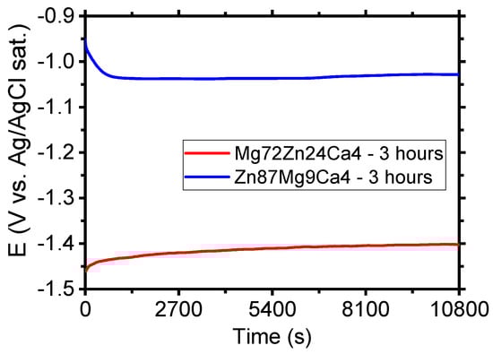
Figure 6.
Evolution of open circuit potential (OCP) for Mg72Zn24Ca4 and Zn87Mg9Ca4 alloys specimens in Ringer’s solution at 37 °C; pH 7.2 after 3 h.
Figure 7 shows the evolution of open circuit potential (OCP) for the Mg72Zn24Ca4 bulk material sample (before the melt spinning process) and Mg72Zn24Ca4 ribbon (after the melt spinning process) specimens in the Ringer solution. After four thousand seconds of immersion of specimens in the Ringer solution, the following values of OCP were measured: −1.417 V and −1.284 V for Mg72Zn24Ca4 bulk material sample and Mg72Zn24Ca4 for ribbon specimens, respectively. The OCP measured for Mg72Zn24Ca4 ribbon is 133 mV higher than the one measured for the Mg72Zn24Ca4 bulk material sample.
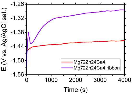
Figure 7.
Evolution of OCP for Mg72Zn24Ca4 bulk material and Mg72Zn24Ca4 ribbon specimens in Ringer’s solution at 37 °C; pH 7.2 after four thousand seconds.
Figure 8 depicts the evolution of open circuit potential (OCP) for the Zn87Mg9Ca4 bulk material sample (before the melt spinning process) and Zn87Mg9Ca4 ribbon (after the melt spinning process) specimens in the Ringer solution. After four thousand seconds of immersion of specimens in the Ringer solution, the following values of OCP were measured: −1.048 V and −1.037 V for Mg72Zn24Ca4 bulk material sample and Mg72Zn24Ca4 for ribbon specimens, respectively. The OCP measured for the Zn87Mg9Ca4 bulk material sample is 11 mV higher than the one measured for the Zn87Mg9Ca4 ribbon.
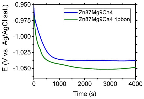
Figure 8.
Evolution of OCP for Zn87Mg9Ca4 bulk material and Zn87Mg9Ca4 ribbon specimens in Ringer’s solution at 37 °C; pH 7.2 after four thousand seconds.
The increase in corrosion potential versus time can cause: the formation of the passive film, the decrease in anodic reaction rate, or the increase in the cathodic reaction rate. The increase in cathodic reaction is related with the increase in oxygen concentration dissolved in the solution [].
Figure 9 depicts the polarization curves determined for Mg72Zn24Ca4 and Zn87Mg9Ca4 in the Ringer solution. The Mg72Zn24Ca4 exhibits the active corrosion. In the anodic branch, the sharp increase in the current density is observed. The increase in the anodic current density is related with the dissolution of magnesium according with the reaction (1).
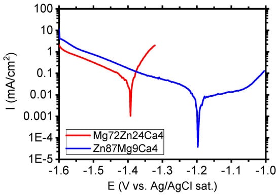
Figure 9.
Polarization curves performed for Mg72Zn24Ca4 and Zn87Mg9Ca4 alloys in Ringer’s solution at 37 °C, pH 7.2.
During the cathodic process, the hydrogen is evolved, and the hydroxide ions are formed, as shown in reaction (2).
The reaction of Mg2+ ions with the OH- ions cause the formation of corrosion product Mg(OH)2. The corrosion products, which contain mainly Mg(OH)2, are porous and do not protect the surface of alloy against corrosion. The current density registered in the cathodic branch for Zn87Mg9Ca4 (blue curve) is higher than the one measured for Mg alloy (red curve) in Figure 9. This suggests that the oxygen reduction (cathodic reaction) is promoted on the surface of the Zn87Mg9Ca4 alloy. In the anodic domain, the current plateau is visible in the potential range between −1.2 V and −1.05 V. The current density in the plateau is 11 µA/cm2. This result indicates that the Zn87Mg9Ca4 alloy undergoes the passivation in the Ringer solution. At potential values higher than −1.0 V, the passive film undergoes the anodic dissolution and corrosion of the Zn87Mg9Ca4 alloy.
The corrosion tests performed in the Ringer solution have revealed that the zinc alloy, Zn87Mg9Ca4, exhibits higher corrosion resistance than the Mg72Zn24Ca4 alloy.
Figure 10 depicts the polarization curves determined for Mg72Zn24Ca4 bulk material samples (red curves) and Mg72Zn24Ca4 ribbons (violet curves) in the Ringer solution.
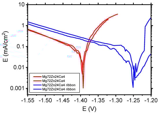
Figure 10.
Polarization curves performed for Mg72Zn24Ca4 bulk material samples and Mg72Zn24Ca4 ribbons in Ringer’s solution at 37 °C, pH 7.2.
The corrosion tests in Figure 10 performed in the Ringer solution have revealed that the Mg72Zn24Ca4 ribbons (blue curves) exhibit higher corrosion resistance than the Mg72Zn24Ca4 bulk material specimens (red curves). The cathodic current density of ribbon is higher compared to the current density registered for bulk material Mg72Zn24Ca4. Such results confirm that the cathodic reaction (HER) proceeds preferentially on ribbon surface. This causes the shift of the corrosion potential of about 150 mV in a more anodic direction. XRD measurements have revealed that the ribbon produced on the base of Mg72Zn24Ca4 has an amorphous structure. The amorphous structure determined better corrosion resistance of ribbons in the Ringer solution.
Figure 11 shows the polarization curves determined for Zn87Mg9Ca4 bulk material samples (blue curves) and Zn87Mg9Ca4 ribbons (olive curves) in the Ringer solution.
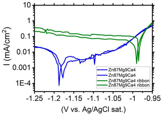
Figure 11.
Polarization curves performed for Zn87Mg9Ca4 bulk material samples (blue curves) and Zn87Mg9Ca4 ribbons (olive curves) in Ringer’s solution at 37 °C, pH 7.2.
Cathodic current density registered for the ribbon surface is one order of magnitude higher compared to the one measured for the bulk material Zn87Mg9Ca. Therefore, the cathodic reaction (HER) proceeds preferentially on the surface of ribbons. XRD measurements (Figure 5) have revealed that the ribbons produced on the base of Zn87Mg9Ca4 are not totally amorphous. When the corrosion potential was reached, the anodic current density sharply increases and no passive range was detected (olive curves, Figure 11). The corrosion tests, such as the evolution of OCP (Figure 8) and LSV (Figure 11), indicate that the Zn87Mg9Ca4 ribbon does not reveal much better corrosion resistance than the bulk alloy. This behavior is related to the partial crystalline structure of ribbons.
Figure 12 depicts fitting results of EIS measurements (Nyquist diagrams) for Mg72Zn24Ca4 (a) and Zn87Mg9Ca4 (b) bulk material samples—before the melt spinning process. The EIS spectra were obtained after 24 h of immersion of both alloys in Ringer’s solution at 37 °C, pH = 7.2.
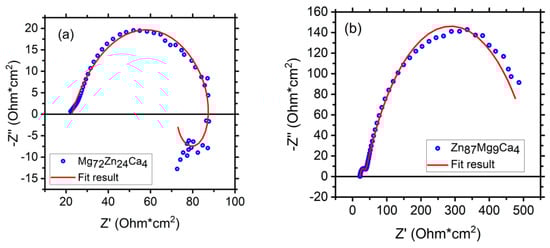
Figure 12.
Polarization curves performed for the Zn87Mg9Ca4 bulk material samples (blue curves) and Zn87Mg9Ca4 ribbons (olive curves) in Ringer’s solution at 37 °C, pH 7.2.
Figure 13 depicts the electrochemical impedance spectrum performed for the Mg72Zn24Ca4 alloy in the Ringer solution at 37 °C and pH 7.2. The EIS spectrum revealed the presence of one capacitive loop at the high frequency range and one inductive loop at the low frequency range. The electrical equivalent circuit (EEC), used to fit the EIS diagram for the Mg72Zn24Ca4 alloy, is shown in Figure 14. The red line represents the results obtained from the fitting of EEC (Figure 14). Due to the deformation of Bode’s diagram in the center (Figure 13), a constant phase element (CPE1) was introduced instead of the capacitor. The (R1) represents the solution resistance and (R2) the charge transfer resistance (the resistance to the electron transfer of the faradic process), respectively. The (CPE1) is a constant phase element related to the surface film resistance, (R3) is surface layer resistance and induction, (L) is related to the adsorption of corrosion products on the surface of the Mg72Zn24Ca4 alloy [,,]. The impedance of constant phase element (CPE) is defined by the following Equation (3) []:
where:
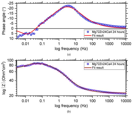
Figure 13.
Bode diagrams (a,b) with respective fitting line for the Mg72Zn24Ca4 alloy sample of immersion at open circuit potential in Ringer’s solution at 37 °C.
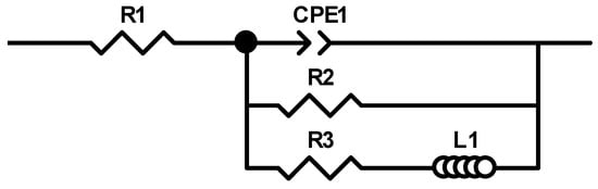
Figure 14.
The equivalent circuit used for fitting the experimental electrochemical impedance spectroscopy (EIS) Mg72Zn24Ca4 sample immersed in Ringer’s solution at 37 °C.
CPE-T—the capacitance parameter in F∙cm−2∙sϕ−1 which depends on the electrode potential.
Φ—is related to the angle of rotation of the pure capacitive line on the complex plane plots: α = 90°(1-ϕ).
When ϕ = 1, Equation (3) represents pure capacitance for infinite Warburg impedance that is obtained for ϕ = 0.5, pure resistance for ϕ = 0, and pure inductance for ϕ = −1.
The fitting parameters obtained from the EIS measurement performed for the Mg72Zn24Ca4 alloy are presented in Table 4.
Table 4.
Fitting parameters obtained from the EIS measurements of the Mg72Zn24Ca4 alloy immersed in the Ringer solution at 37 °C up to 24 h.
Dissolution of the magnesium alloy, according to reaction (1), causes the formation Mg2+ ions and the electrons are transferred through interface metal/electrolyte. The magnesium ions react with the OH- ions and the surface layer consists mainly of the Mg(OH)2 that forms. The corrosion products are deposited on the surface of Mg72Zn24Ca4. Therefore, the inductive loop is visible at the low frequency in the EIS spectrum (Figure 13). The value of CPE1-P equals 0.65, which indicates that the diffusion process proceeds through the surface layer formed on the Mg72Zn24Ca4 alloy. This result indicates that the surface layer (corrosion products) formed on the Mg alloy does not have the capacitive properties.
Figure 15 shows the Bode diagram determined for the Zn87Mg9Ca4 alloy specimen immersed at open circuit potential in Ringer’s solution at 37 °C for 24 h. Blue circles represent the experimental points and the red line represents the results obtained from fitting the electrical equivalent circuit (EEC). The electrical equivalent circuit (EEC) used to fit the EIS diagram obtained for the Zn87Mg9Ca4 alloy is shown in Figure 16. The circuit for this alloy consists of the following elements: R1—solution resistance, R2—change transfer resistance and R3—resistance of the surface layer, CPE1—constant phase element related to the double layer capacity, CPE2—constant phase element related to the surface layer formed at the surface of the Zn87Mg9Ca4 alloy. On the Bode diagram, two capacitive loops are visible, one at the high frequency (HF) and the second at the low frequency (LF).
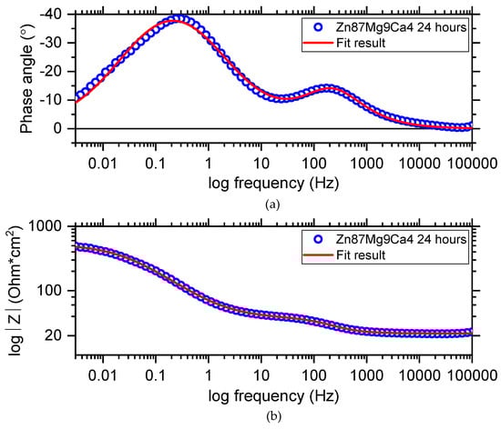
Figure 15.
Bode diagram (a,b) obtained for the Zn87Mg9Ca4 alloy sample immersed at open circuit potential in Ringer’s solution at 37 °C for 24 h.
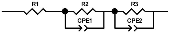
Figure 16.
Bode diagram (a,b) obtained for the Zn87Mg9Ca4 alloy sample immersed at open circuit potential in Ringer’s solution at 37 °C for 24 h.
The change transfer reaction is related to the dissolution of Zn alloys into electrolytes according to reaction (4).
During the cathodic process (HER, reaction (2)), hydroxide ions are produced, and then they react with the Zn2+ ions and a zinc hydroxide layer is formed at the surface of the Zn87Mg9Ca4 alloy; reaction (5).
The presence of the high concentration of Cl− ions in the Ringer solution causes their diffusion through the surface layer, and converts Zn(OH)2 to more soluble chloride salts Zn5(OH)8Cl2. The CPE2-P values equal 0.67 (Table 5), confirming that the diffusion of Cl- ions through the hydroxides layer can take place.
Table 5.
Fitting parameters obtained from the EIS measurements of the Zn87Mg9Ca4 alloy immersed in Ringer’s solution at 37 °C for 24 h.
In order to summarize, the obtained results clearly show that the bulk material, Zn87Mg9Ca4, exhibits higher corrosion resistance than the Mg72Zn24Ca4 alloy. Both alloys contain the same amount of calcium. Notably, the ratio of zinc to magnesium is different, being 3/1 and 9/1 for Mg72Zn24Ca4 and Zn87Mg9Ca4 alloys, respectively. The higher ratio of zinc to magnesium results in the cathodic and anodic processes. The higher current density in the cathodic branch is measured for Zn87Mg9Ca4 alloy. In turn, in the anodic branch, the passive region is visible for the Zn87Mg9Ca4 alloy. The high ratio of zinc to magnesium causes the formation of the passive film on its surface, which consists mainly of zinc oxide and zinc hydroxides. Comparison of corrosion behavior of bulk and ribbon materials exhibits the significant difference between them, especially in the cathodic area. The cathodic current density was higher for ribbons of both alloys. This effect is significantly noticeable especially for Zn87Mg9Ca4 alloy where the cathodic current density is one order of magnitude higher compared to the bulk material (Figure 11). XRD measurements have revealed that the ribbon obtained for the Zn87Mg9Ca4 alloy has a partially crystalline microstructure. During the melt spinning process, the cooling rate is very fast which causes the formation of a refine microstructure. The presence of numerous grain boundaries promotes the cathodic reduction reaction (HER) and hinders the passivation process, as is shown in Figure 11 (olive curves). Similar to the results obtained by other researchers [,], these results confirm that the amorphous microstructure has a beneficial effect on the corrosion resistance of magnesium-based alloys in Ringer’s solution.
4. Conclusions
The corrosion tests have revealed that the Mg72Zn24Ca4 alloy undergoes the active corrosion in the Ringer solution. However, the Zn87Mg9Ca4 alloy undergoes the passivation but at potential values higher than −1.05 E (V vs. Ag/AgCl) (3M KCl), hence, the active dissolution of Zn alloy proceeds. It should be noticed that the cathodic reaction (HER) is favored at the surface of the Zn87Mg9Ca4 alloy. The corrosion of the Mg72Zn24Ca4 alloy in the Ringer solution is related to the dissolution of Mg, and then, to the adsorption of the corrosion product, Mg(OH)2, on its surface. Degradation of the Zn87Mg9Ca4 alloy in the Ringer solution consists of two consecutive steps: (1) formation of the surface layer, (2) diffusion of the chloride ions through the surface layer.
The corrosion tests have revealed that the Zn87Mg9Ca4 alloy (bulk material) exhibits significantly higher corrosion resistance than the Mg72Zn24Ca4 alloy (bulk material) in the Ringer solution. The results obtained in this study has revealed that if the ribbons are amorphous, they exhibit better corrosion resistance than bulk material samples. This fact is confirmed by the observed higher cathodic current density for ribbons and their longer cathodic branch in relation to the bulk material samples.
This result indicates that the cathodic reaction proceeds faster on the surface of the ribbon.
The metallic materials, which are potential candidates for biomedical application, should be nontoxic and their corrosion degradation cannot be very fast. The obtained results have revealed that in the case of magnesium alloys, the amorphous microstructure significantly hinders their corrosion in physiological solution. Therefore, it is necessary to pay much attention to the optimization of the chemical composition of magnesium and zinc alloys and the parameters of the melt spinning process to obtain the amorphous microstructure of biomaterials.
Author Contributions
Conceptualization, methodology, writing—original draft preparation, A.F., J.L. and H.K.; formal analysis, writing—review and editing, A.F., J.L. and H.K., alloy preparation and casting of metallic glasses ribbons, performing of XRD measurements—Ł.R., performing of LSV measurements—J.R. All authors have read and agreed to the published version of the manuscript.
Funding
This research was funded by AGH University, grant number 16.16.170.654.
Conflicts of Interest
The author declares no conflict of interest.
References
- Li, L.; Gao, J.; Wang, Y. Evaluation of cyto-toxicity and corrosion behavior of alkali-heat-treated magnesium in simulated body fluid. Surf. Coatings Technol. 2004, 185, 92–98. [Google Scholar] [CrossRef]
- Witte, F.; Kaese, V.; Haferkamp, H.; Switzer, E.; Meyer-Lindenberg, A.; Wirth, C.; Windhagen, H. In vivo corrosion of four magnesium alloys and the associated bone response. Biomaterials 2005, 26, 3557–3563. [Google Scholar] [CrossRef] [PubMed]
- Al-Abdullat, Y.; Tsutsumi, S.; Nakajima, N.; Ohta, M.; Kuwahara, H.; Ikeuchi, K. Surface Modification of Magnesium by NaHCO3 and Corrosion Behavior in Hank’s solution for New Biomaterial Applications. Mater. Trans. 2001, 42, 1777–1780. [Google Scholar] [CrossRef]
- Tang, J.; Wang, J.; Xie, X.; Zhang, P.; Lai, Y.; Li, Y.; Qin, L. Surface coating reduces degradation rate of magnesium alloy developed for orthopaedic applications. J. Orthop. Transl. 2013, 1, 41–48. [Google Scholar] [CrossRef]
- Li, H.F.; Xie, X.H.; Zheng, Y.; Cong, Y.; Zhou, F.Y.; Qiu, K.J.; Wang, X.; Chen, S.H.; Huang, L.; Tian, L.; et al. Development of biodegradable Zn-1X binary alloys with nutrient alloying elements Mg, Ca and Sr. Sci. Rep. 2015, 5, 10719. [Google Scholar] [CrossRef] [PubMed]
- Li, Z.; Gu, X.; Lou, S.; Zheng, Y. The development of binary Mg–Ca alloys for use as biodegradable materials within bone. Biomaterials 2008, 29, 1329–1344. [Google Scholar] [CrossRef] [PubMed]
- Peng, Q.; Huang, Y.; Zhou, L.; Hort, N.; Kainer, K.U. Preparation and properties of high purity Mg–Y biomaterials. Biomaterials 2010, 31, 398–403. [Google Scholar] [CrossRef]
- Peng, Q.M.; Dong, H.W.; Tian, Y.; Zhang, H.J. Development of Degradable Mg-RE Based Biomaterials. Adv. Mater. Res. 2012, 509, 36–39. [Google Scholar] [CrossRef]
- Gu, X.; Xie, X.; Li, N.; Zheng, Y.; Qin, L. In vitro and in vivo studies on a Mg–Sr binary alloy system developed as a new kind of biodegradable metal. Acta Biomater. 2012, 8, 2360–2374. [Google Scholar] [CrossRef]
- Zhao, X.; Shi, L.-L.; Xu, J. Biodegradable Mg–Zn–Y alloys with long-period stacking ordered structure: Optimization for mechanical properties. J. Mech. Behav. Biomed. Mater. 2013, 18, 181–190. [Google Scholar] [CrossRef] [PubMed]
- Chen, S.; Smith, C.E.; Xu, Z.; Sankar, J. Development of Biodegradable Mg-Zn-Ca Alloys for Biomedical Applications. Proc. Eng. Appl. Nov. Mater. 2010, 12, 43–48. [Google Scholar] [CrossRef]
- Zberg, B.; Uggowitzer, P.J.; Löffler, J. MgZnCa glasses without clinically observable hydrogen evolution for biodegradable implants. Nat. Mater. 2009, 8, 887–891. [Google Scholar] [CrossRef] [PubMed]
- Gu, X.; Zheng, Y.; Zhong, S.; Xi, T.; Wang, J.; Wang, W. Corrosion of, and cellular responses to Mg–Zn–Ca bulk metallic glasses. Biomaterials 2010, 31, 1093–1103. [Google Scholar] [CrossRef] [PubMed]
- Zheng, Y.; Gu, X.; Witte, F. Biodegradable metals. Mater. Sci. Eng. R Rep. 2014, 77, 1–34. [Google Scholar] [CrossRef]
- Bowen, P.K.; Drelich, J.; Goldman, J. Zinc Exhibits Ideal Physiological Corrosion Behavior for Bioabsorbable Stents. Adv. Mater. 2013, 25, 2577–2582. [Google Scholar] [CrossRef] [PubMed]
- Institute of Medicine (US) Standing Committee on the Scientific Evaluation of Dietary Reference Intakes. Dietary Reference Intakes for Calcium, Phosphorus, Magnesium, Vitamin D, and Fluoride; National Academies Press: Washington, DC, USA, 1997. [Google Scholar]
- Vormann, J. Magnesium: Nutrition and metabolism. Mol. Asp. Med. 2003, 24, 27–37. [Google Scholar] [CrossRef]
- Institute of Medicine (US) Panel on Micronutrients. Dietary Reference Intakes for Vitamin A, Vitamin K, Arsenic, Boron, Chromium, Copper, Iodine, Iron, Manganese, Molybdenum, Nickel, Silicon, Vanadium, and Zinc; National Academies Press: Washington, DC, USA, 2001. [Google Scholar]
- Robinson, D.; Griffith, R.W.; Shechtman, D.; Evans, R.B.; Conzemius, M.G. In vitro antibacterial properties of magnesium metal against Escherichia coli, Pseudomonas aeruginosa and Staphylococcus aureus. Acta Biomater. 2010, 6, 1869–1877. [Google Scholar] [CrossRef]
- Sheng, J.; Nguyen, P.T.; Marquis, R.E. Multi-target antimicrobial actions of zinc against oral anaerobes. Arch. Oral Boil. 2005, 50, 747–757. [Google Scholar] [CrossRef]
- Neil, W.; Forsyth, M.; Howlett, P.C.; Hutchinson, C.; Hinton, B. Corrosion of magnesium alloy ZE41—The role of microstructural features. Corros. Sci. 2009, 51, 387–394. [Google Scholar] [CrossRef]
- Hermann, F.; Sommer, F.; Jones, H.; Edyvean, R.G.J. Corrosion inhibition in magnesium-aluminium-based alloys induced by rapid solidification processing. J. Mater. Sci. 1989, 24, 2369–2379. [Google Scholar] [CrossRef]
- Zhao, M.-C.; Liu, M.; Song, G.-L.; Atrens, A. Influence of the β-phase morphology on the corrosion of the Mg alloy AZ91. Corros. Sci. 2008, 50, 1939–1953. [Google Scholar] [CrossRef]
- Kot, I.; Krawiec, H. The use of a multiscale approach in electrochemistry to study the corrosion behaviour of as-cast AZ91 magnesium alloy. J. Solid State Electrochem. 2015, 19, 2379–2390. [Google Scholar] [CrossRef]
- Scully, J.R.; Gebert, A.; Payer, J.H. Corrosion and related mechanical properties of bulk metallic glasses. J. Mater. Res. 2007, 22, 302–313. [Google Scholar] [CrossRef]
- Schlüter, K.; Zamponi, C.; Hort, N.; Kainer, K.; Quandt, E. Polycrystalline and amorphous MgZnCa thin films. Corros. Sci. 2012, 63, 234–238. [Google Scholar] [CrossRef]
- Vojtech, D.; Kubásek, J.; Šerák, J.; Novak, P. Mechanical and corrosion properties of newly developed biodegradable Zn-based alloys for bone fixation. Acta Biomater. 2011, 7, 3515–3522. [Google Scholar] [CrossRef]
- Kubásek, J.; Vojtěch, D. Zn-based alloys as an alternative biodegradable materials. Proc. Metal 2012, 5, 23–25. [Google Scholar]
- Murni, N.; Dambatta, M.; Yeap, S.K.; Froemming, G.; Hermawan, H. Cytotoxicity evaluation of biodegradable Zn–3Mg alloy toward normal human osteoblast cells. Mater. Sci. Eng. C 2015, 49, 560–566. [Google Scholar] [CrossRef]
- Liu, X.; Sun, J.; Qiu, K.; Yang, Y.; Pu, Z.; Li, L.; Zheng, Y.-F. Effects of alloying elements (Ca and Sr) on microstructure, mechanical property and in vitro corrosion behavior of biodegradable Zn–1.5Mg alloy. J. Alloy. Compd. 2016, 664, 444–452. [Google Scholar] [CrossRef]
- Li, H.; Yang, H.; Zheng, Y.; Zhou, F.; Qiu, K.; Wang, X. Design and characterizations of novel biodegradable ternary Zn-based alloys with IIA nutrient alloying elements Mg, Ca and Sr. Mater. Des. 2015, 83, 95–102. [Google Scholar] [CrossRef]
- Hänsch, R.; Mendel, R.R. Physiological functions of mineral micronutrients (Cu, Zn, Mn, Fe, Ni, Mo, B, Cl). Curr. Opin. Plant Boil. 2009, 12, 259–266. [Google Scholar] [CrossRef]
- Li, N.; Zheng, Y. Novel Magnesium Alloys Developed for Biomedical Application: A Review. J. Mater. Sci. Technol. 2013, 29, 489–502. [Google Scholar] [CrossRef]
- Ilich, J.Z.; Kerstetter, J.E. Nutrition in bone health revisited: A story beyond calcium. J. Am. Coll. Nutr. 2001, 19, 715–737. [Google Scholar] [CrossRef] [PubMed]
- Li, Y.; Wen, C.; Mushahary, D.; Sravanthi, R.; Harishankar, N.; Pande, G.; Hodgson, P. Mg–Zr–Sr alloys as biodegradable implant materials. Acta Biomater. 2012, 8, 3177–3188. [Google Scholar] [CrossRef] [PubMed]
- Tok, H.; Hamzah, E.; Bakhsheshi-Rad, H. The role of bismuth on the microstructure and corrosion behavior of ternary Mg–1.2Ca–xBi alloys for biomedical applications. J. Alloy. Compd. 2015, 640, 335–346. [Google Scholar] [CrossRef]
- Lu, Y.; Bradshaw, A.; Chiu, Y.; Jones, I. The role of β1′ precipitates in the bio-corrosion performance of Mg–3Zn in simulated body fluid. J. Alloy. Compd. 2014, 614, 345–352. [Google Scholar] [CrossRef]
- Homayun, B.; Afshar, A. Microstructure, mechanical properties, corrosion behavior and cytotoxicity of Mg–Zn–Al–Ca alloys as biodegradable materials. J. Alloy. Compd. 2014, 607, 1–10. [Google Scholar] [CrossRef]
- Schinhammer, M.; Hänzi, A.C.; Löffler, J.F.; Uggowitzer, P. Design strategy for biodegradable Fe-based alloys for medical applications. Acta Biomater. 2010, 6, 1705–1713. [Google Scholar] [CrossRef]
- Serre, C.M.; Papillard, M.; Chavassieux, P.; Voegel, J.C.; Boivin, G. Influence of magnesium substitution on a collagen-apatite biomaterial on the production of a calcifying matrix by human osteoblasts. J. Biomed. Mater. Res. 1998, 42, 626–633. [Google Scholar] [CrossRef]
- Avedesian, M.M.; Baker, H. ASM Specialty Handbook: Magnesium and Magnesium Alloys; ASM International: Novelty, OH, USA, 1999. [Google Scholar]
- Gu, X.; Li, N.; Zheng, Y.; Ruan, L. In vitro degradation performance and biological response of a Mg–Zn–Zr alloy. Mater. Sci. Eng. B 2011, 176, 1778–1784. [Google Scholar] [CrossRef]
- Rad, H.R.B.; Idris, M.H.; Kadir, M.R.A.; Farahany, S. Microstructure analysis and corrosion behavior of biodegradable Mg-Ca implant alloys. Mater. Des. 2012, 33, 88–97. [Google Scholar] [CrossRef]
- Jiang, Q.; Yang, L.; Hou, B. The Effect of Deep Cryogenic Treatment on the Corrosion Behavior of Mg-7Y-1.5Nd Magnesium Alloy. Metals 2017, 7, 427. [Google Scholar] [CrossRef]
- Paul, S.; Ramasamy, P.; Das, M.; Mandal, D.; Renk, O.; Calin, M.; Eckert, J.; Bera, S. New Mg-Ca-Zn amorphous alloys: Biocompatibility, wettability and mechanical properties. Materials 2020, 12, 100799. [Google Scholar] [CrossRef]
- Bera, S.; Paul, S.; Ramasamy, P.; Mandal, D.; Das, M.; Lassnig, A.; Renk, O.; Calin, M.; Eckert, J. Synthesis of New Glassy Mg-Ca-Zn Alloys with Exceptionally Low Young’s Modulus: Exploring Near Eutectic Compositions. SSRN Electron. J. 2019, 173, 139–143. [Google Scholar] [CrossRef]
- Niinomi, M. Metals for Biomedical Devices; Elsevier BV: Amsterdam, The Netherlands, 2010. [Google Scholar]
- Veleva, L.; Fernández-Olaya, M.G.; Feliu, J.S. Initial Stages of AZ31B Magnesium Alloy Degradation in Ringer′s Solution: Interpretation of EIS, Mass Loss, Hydrogen Evolution Data and Scanning Electron Microscopy Observations. Metals 2018, 8, 933. [Google Scholar] [CrossRef]
- Jamesh, M.; Kumar, S.; Narayanan, T.S. Corrosion behavior of commercially pure Mg and ZM21 Mg alloy in Ringer’s solution—Long term evaluation by EIS. Corros. Sci. 2011, 53, 645–654. [Google Scholar] [CrossRef]
- Li, Z.; Song, G.; Song, S. Effect of bicarbonate on biodegradation behaviour of pure magnesium in a simulated body fluid. Electrochim. Acta 2014, 115, 56–65. [Google Scholar] [CrossRef]
- Lasia, A. Electrochemical Impedance Spectroscopy and Its Applications; Springer Science and Business Media LLC: Berlin/Heidelberg, Germany, 2014. [Google Scholar]
© 2020 by the authors. Licensee MDPI, Basel, Switzerland. This article is an open access article distributed under the terms and conditions of the Creative Commons Attribution (CC BY) license (http://creativecommons.org/licenses/by/4.0/).