Microstructure and Wear Behavior of In-Situ NbC Reinforced Composite Coatings

Abstract
:1. Introduction
2. Materials and Methods
3. Results and Discussion
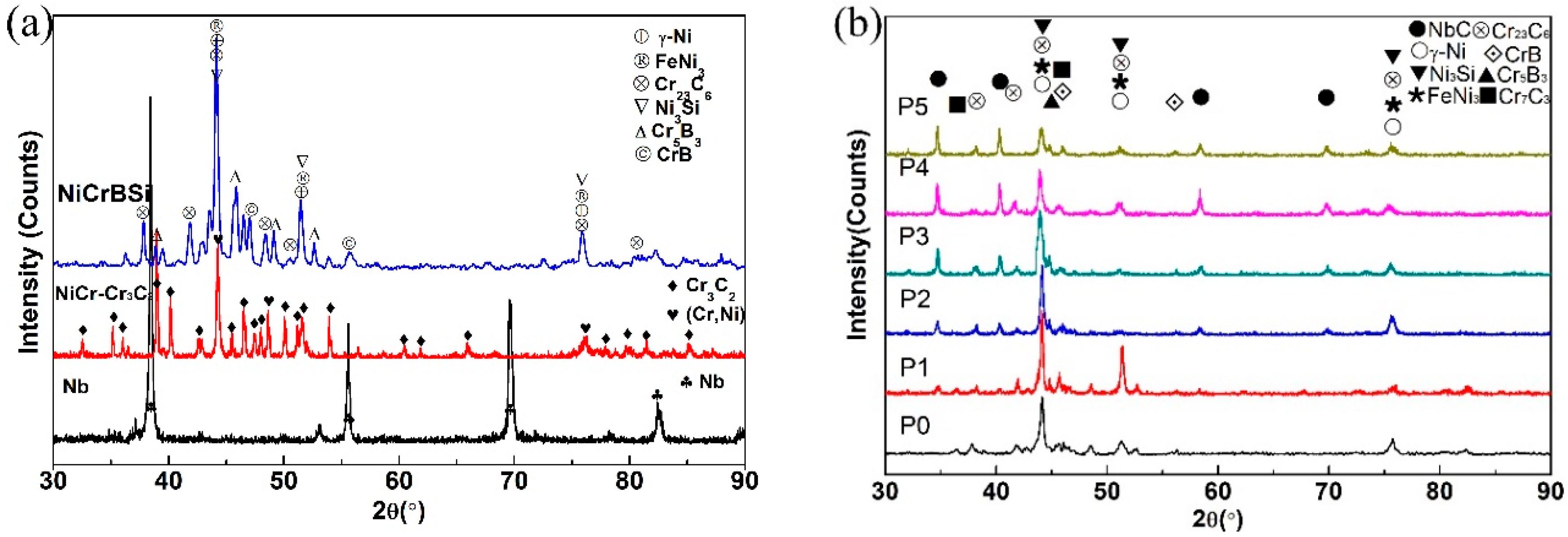
3.1. XRD Analysis
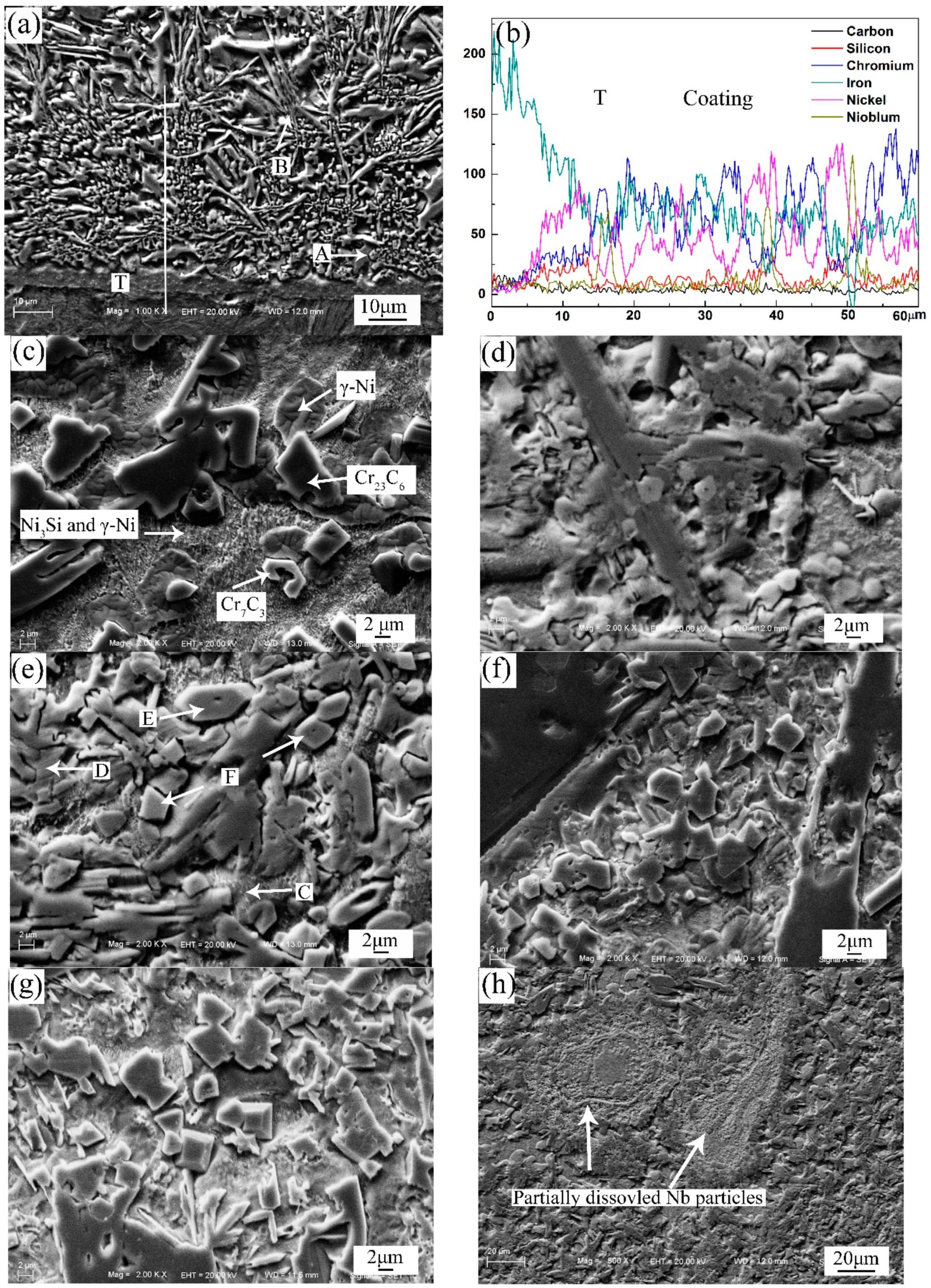
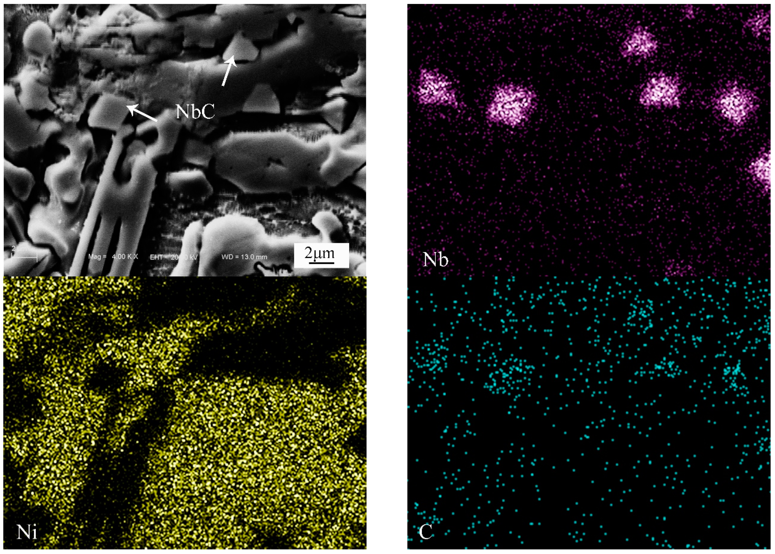
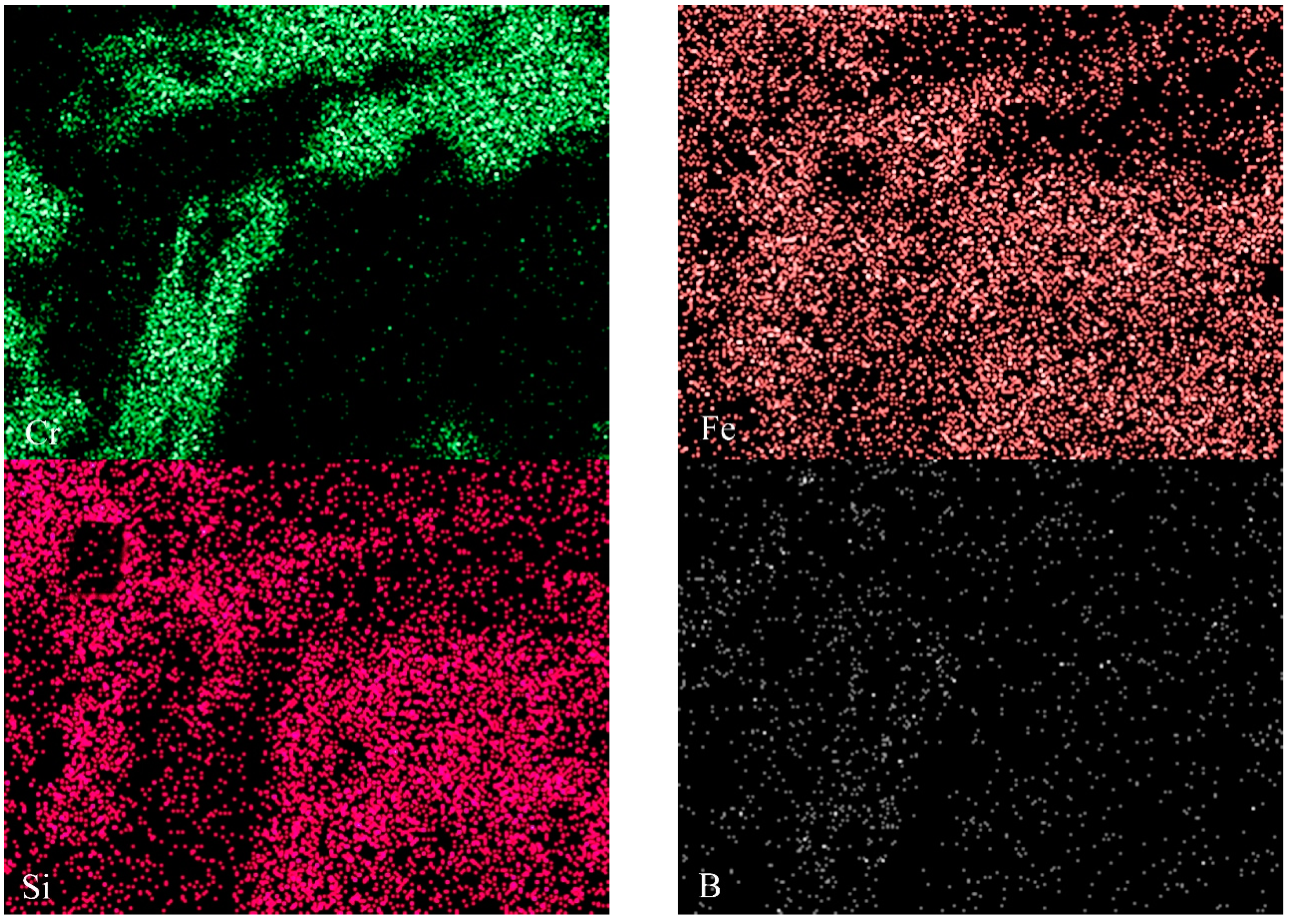
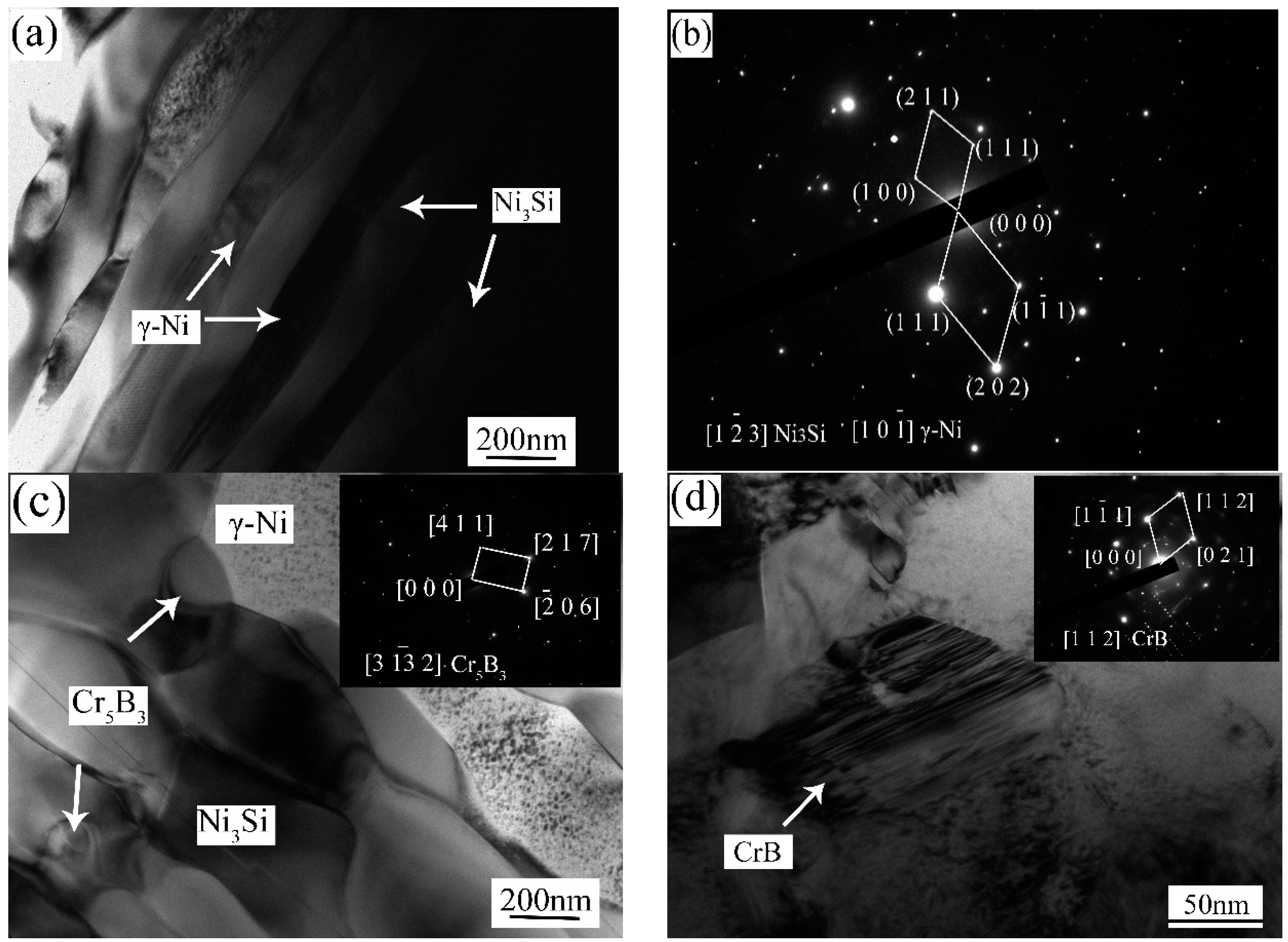
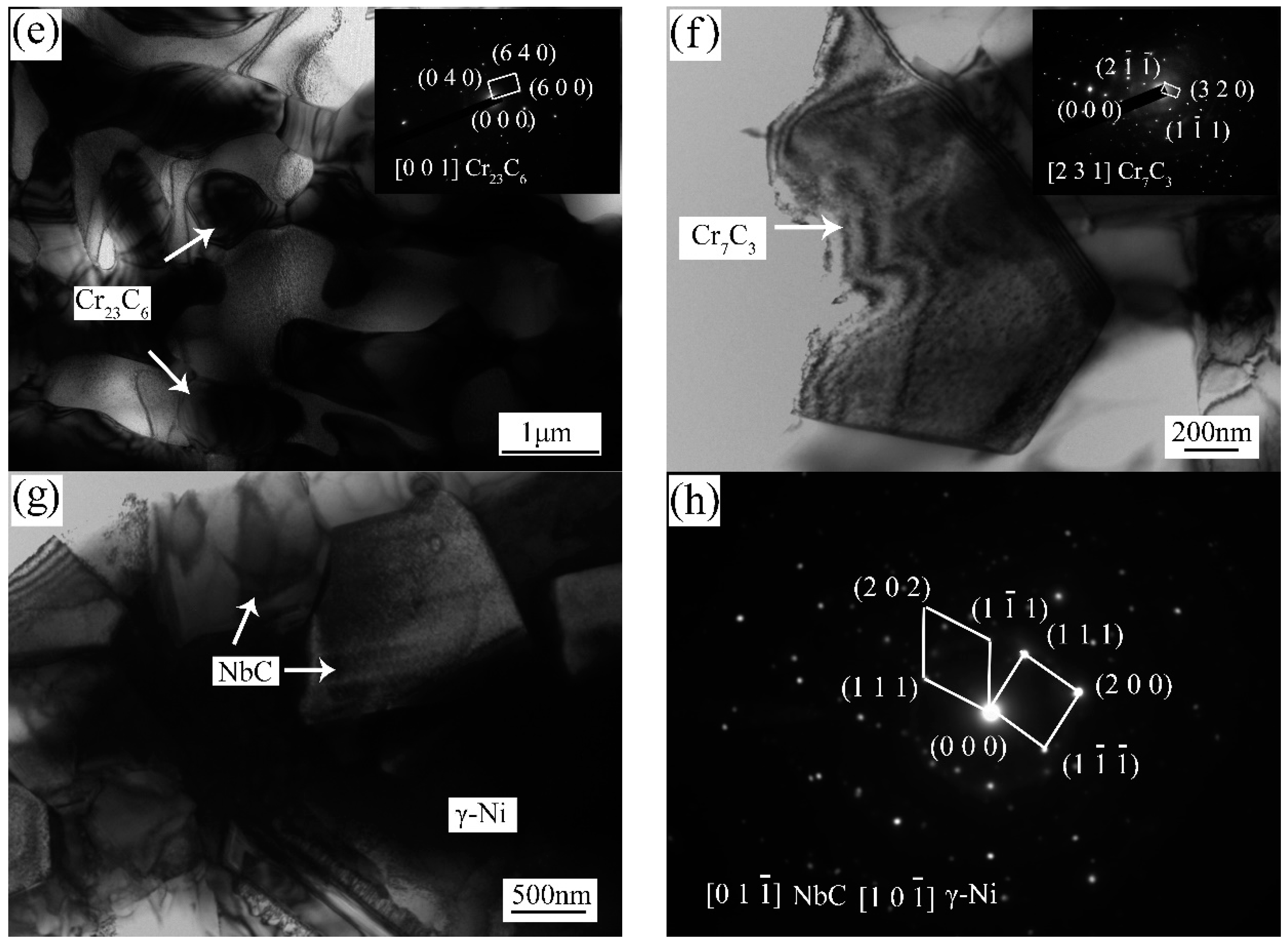
3.2. Microstructure
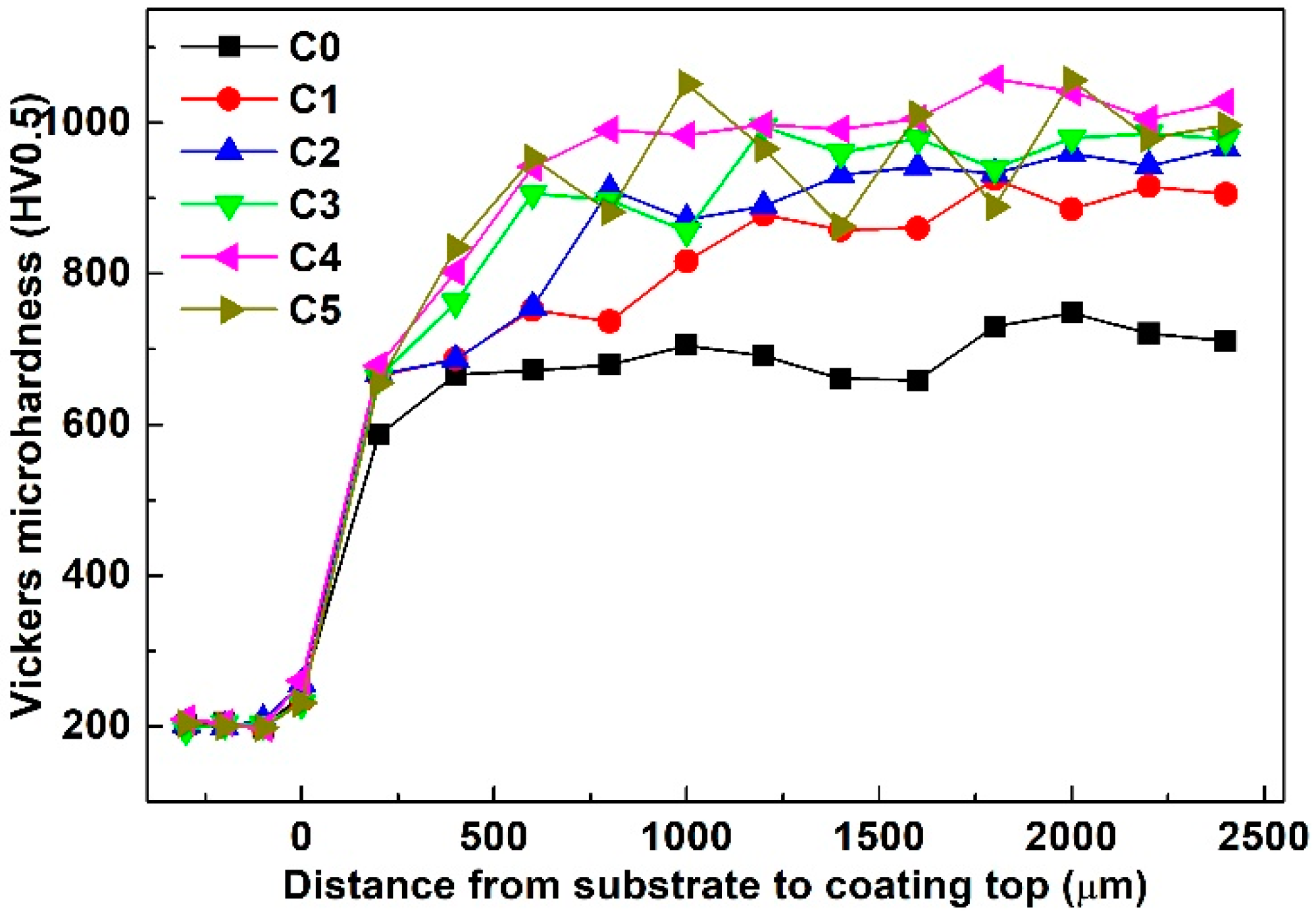
3.3. Micro-Hardness
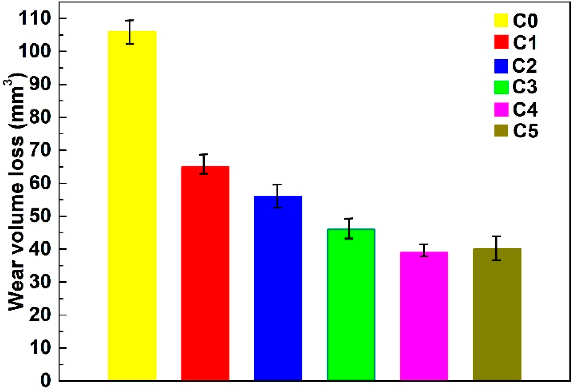
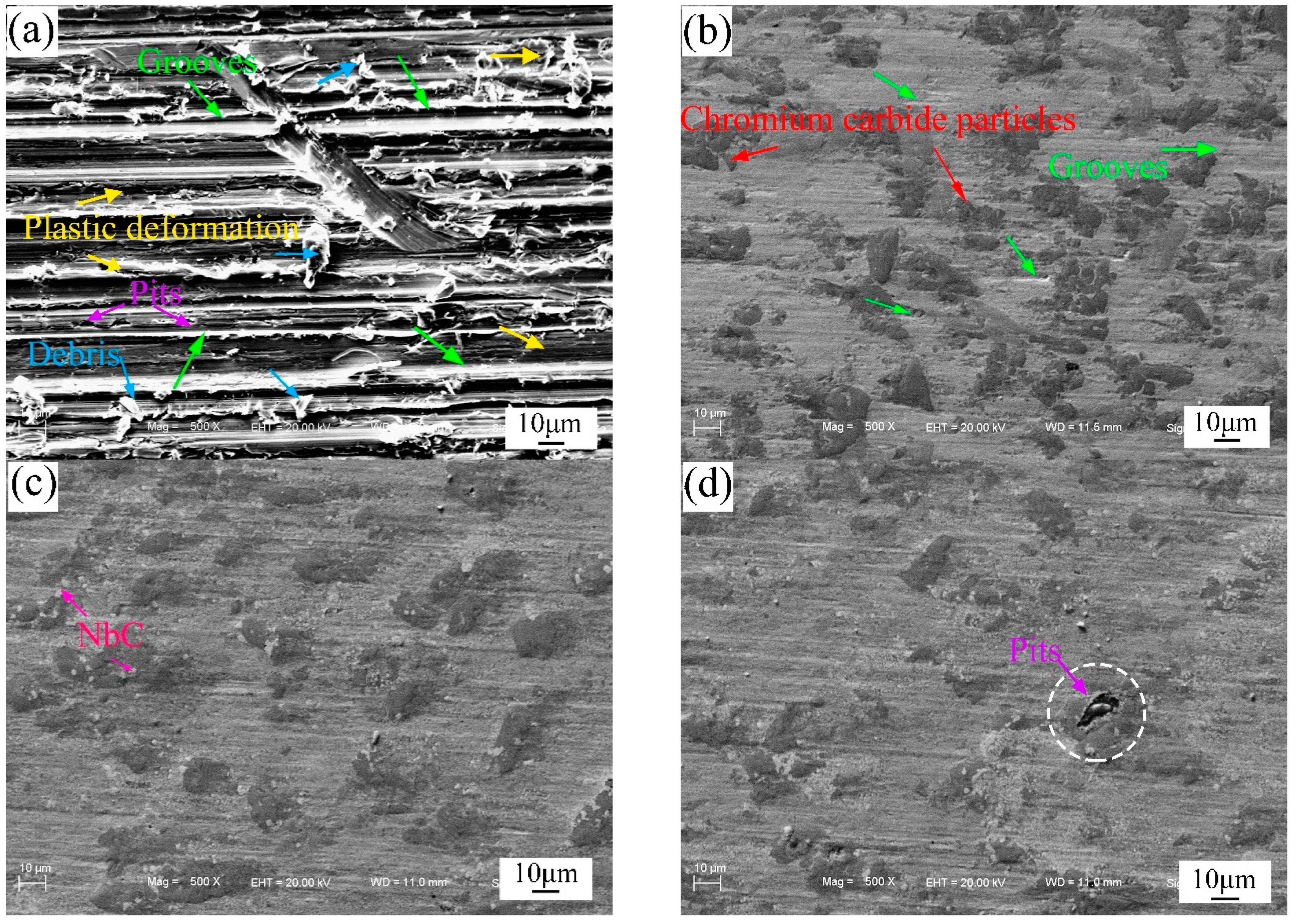
3.4. Wear Resistance
4. Conclusions
Author Contributions
Funding
Conflicts of Interest
References
- Liu, Y.S.; Cheng, L.F.; Zhang, L.T.; Hua, Y.F.; Yang, W.B. Microstructure and properties of particle reinforced silicon carbide and silicon nitride ceramic matrix composites prepared by chemical vapor infiltration. Mater. Sci. Eng. A 2008, 475, 217–223. [Google Scholar] [CrossRef]
- Zhao, F.L.; Fu, Q.G.; Feng, L.; Shen, Q.L. Enhancement of C/C-LAS joint using aligned carbon nanotubes prepared by injection chemical vapor deposition. Mater. Sci. Eng. A 2016, 650, 67–74. [Google Scholar] [CrossRef]
- Yang, T.M.; Wei, Q.P.; Qi, Y.; Wang, Y.J.; Xie, Y.N.; Luo, J.Q.; Yu, Z.M. Microstructure evolution of thermal spray WC-Co interlayer during hot filament chemical vapor deposition of diamond thin films. J. Alloys Compd. 2015, 639, 659–668. [Google Scholar] [CrossRef]
- Rafiei, M.; Salehi, M.; Shamanian, M.; Motallebzadeh, A. Preparation and oxidation behavior of B4C-Ni and B4C-TiB2-TiC-Ni composite coatings produced by an HVOF process. Ceram. Int. 2014, 40, 13599–13609. [Google Scholar] [CrossRef]
- Liu, H.Y.; Huang, J.H.; Yin, C.F.; Zhang, J.G.; Lin, G.B. Microstructure and properties of TiC-Fe cermet coatings by reactive flame spraying using asphalt as carbonaceous precursor. Ceram. Int. 2007, 33, 827–835. [Google Scholar] [CrossRef]
- Savalani, M.M.; Ng, C.C.; Li, Q.H.; Man, H.C. In situ formation of titanium carbide using titanium and carbon-nanotube powders by laser cladding. Appl. Surf. Sci. 2012, 258, 3173–3177. [Google Scholar] [CrossRef]
- Emamian, A.; Corbin, S.F.; Khajepour, A. Effect of laser cladding process parameters on clad quality and in-situ formed microstructure of Fe-TiC composite coatings. Surf. Coat. Technol. 2010, 205, 2007–2015. [Google Scholar] [CrossRef]
- Zheng, B.J.; Chen, X.M.; Lian, J.S. Microstructure and wear property of laser cladding Al+SiC powders on AZ91D magnesium alloy. Opt. Laser. Eng. 2010, 48, 526–532. [Google Scholar] [CrossRef]
- Zhou, S.F.; Dai, X.Q. Laser induction hybrid rapid cladding of WC particles reinforced NiCrBSi composite coatings. Appl. Surf. Sci. 2010, 256, 4708–4714. [Google Scholar] [CrossRef]
- Yang, J.X.; Liu, F.L.; Miao, X.H.; Yang, F. Influence of laser cladding process on the magnetic properties of WC-FeNiCr metal-matrix composite coatings. J. Mater. Process. Tech. 2012, 212, 1862–1868. [Google Scholar] [CrossRef]
- Nurminen, J.; Näkki, J.; Vuoristo, P. Microstructure and properties of hard and wear resistant MMC coatings deposited by laser cladding. Int. J. Refract. Met. Hard Mater. 2009, 27, 472–478. [Google Scholar] [CrossRef]
- Jafari, M.; Enayati, M.H.; Salehi, M.; Nahvi, S.M.; Park, C.G. Microstructural and mechanical characterizations of a novel HVOF-sprayed WC-Co coating deposited from electroless Ni-P coated WC-12Co powders. Mater. Sci. Eng. A 2013, 578, 46–53. [Google Scholar] [CrossRef]
- Melendez, N.M.; Narulkar, V.V.; Fisher, G.A.; Fisher, G.A.; McDonald, A.G. Effect of reinforcing particles on the wear rate of low-pressure cold-sprayed WC-based MMC coatings. Wear 2013, 306, 185–195. [Google Scholar] [CrossRef]
- Lin, Y.C.; Chen, H.M.; Chen, Y.C. Analysis of microstructure and wear performance of SiC clad layer on SKD61 die steel after gas tungsten arc welding. Mater. Des. 2013, 47, 828–835. [Google Scholar] [CrossRef]
- Du, B.S.; Zou, Z.D.; Wang, X.H.; Qu, S.Y. Laser cladding of in situ TiB2/Fe composite coating on steel. Appl. Surf. Sci. 2008, 254, 6489–6494. [Google Scholar] [CrossRef]
- Huang, M.L.; Yang, F.; Zhao, N.; Zhang, Z.J. In situ study on dissolution and growth mechanism of interfacial Cu6Sn5 in wetting reaction. Mater. Lett. 2015, 139, 42–45. [Google Scholar] [CrossRef]
- Shi, B.M.; Huang, S.M.; Zhu, P.; Xu, C.E.; Fu, Y.Y. In-situ TiN reinforced composite coatings prepared by plasma spray welding on Ti6Al4V. Mater. Lett. 2020, 276, 128093. [Google Scholar] [CrossRef]
- Chang, F.; Gu, D.D.; Dai, D.H.; Yuan, P.P. Selective laser melting of in-situ Al4SiC4+SiC hybrid reinforced Al matrix composites: Influence of starting SiC particle size. Surf. Coat. Technol. 2015, 272, 15–24. [Google Scholar] [CrossRef]
- Zikin, A.; Antonov, M.; Hussainova, I.; Katona, L.; Gavrilović, A. High temperature wear of cermet particle reinforced NiCrBSi hardfacings. Tribol. Int. 2013, 68, 45–55. [Google Scholar] [CrossRef]
- Lee, C.; Park, H.; Yoo, J.; Lee, C.; Woo, W.; Park, S. Residual stress and crack initiation in laser clad composite layer with Co-based alloy and WC+NiCr. Appl. Surf. Sci. 2015, 345, 286–294. [Google Scholar] [CrossRef]
- Verdi, D.; Garrido, M.A.; Múnez, C.J.; Poza, P. Cr3C2 incorporation into an Inconel 625 laser cladded coating: Effects on matrix microstructure, mechanical properties and local scratch resistance. Mater. Des. 2015, 67, 20–27. [Google Scholar] [CrossRef]
- Liu, S.L.; Zheng, X.P. Microstructure and properties of AC-HVAF sprayed Ni60/WC composite coating. J. Alloys Compd. 2009, 480, 254–258. [Google Scholar] [CrossRef]
- Das, M.; Balla, V.K.; Basu, D.; Manna, I.; Sampath Kumar, T.S.; Bandyopadhyay, A. Laser processing of in situ synthesized TiB-TiN-reinforced Ti6Al4V alloy coatings. Scr. Mater. 2012, 66, 578–581. [Google Scholar] [CrossRef]
- Li, Q.T.; Lei, Y.P.; Fu, H.G. Laser cladding in-situ NbC particle reinforced Fe-based composite coatings with rare earth oxide addition. Surf. Coat. Technol. 2014, 239, 102–107. [Google Scholar] [CrossRef]
- Cao, Y.B.; Ren, H.T.; Hu, C.S.; Meng, Q.X.; Liu, Q. In-situ formation behavior of NbC-reinforced Fe-based laser cladding coatings. Mater. Lett. 2015, 147, 61–63. [Google Scholar] [CrossRef]
- Zhao, N.N.; Xu, Y.H.; Huang, X.; Zhong, L.S.; Lu, J.L. Microstructure and wear properties of niobium carbide particulates gradient-distribution composite layer fabricated in situ. Ceram. Int. 2016, 42, 18507–18515. [Google Scholar] [CrossRef]
- Cai, X.L.; Xu, Y.H. Microstructure, friction and wear of NbC coatings on a Fe substrate fabricated via an in situ reaction. Surf. Coat. Technol. 2017, 322, 202–210. [Google Scholar] [CrossRef]
- Dong, G.; Yan, B.; Deng, Q.L.; Ting, Y. Microstructure and wear resistance of in situ NbC particles reinforced Ni-based alloy composite coating by laser cladding. J. Wuhan Univ. Technol. Mater. Sci. Ed. 2012, 27, 231–237. [Google Scholar] [CrossRef]
- Huang, S.M.; Sun, D.Q.; Wang, W.Q. Microstructures and properties of Ni based composite coatings prepared by plasma spray welding with mixed powders. Int. J. Refract. Met. Hard Mater. 2015, 52, 36–43. [Google Scholar] [CrossRef]
- Serres, N.; Hlawka, F.; Costil, S.; Langlade, C.; Machi, F. Microstructures and mechanical properties of metallic NiCrBSi and composite NiCrBSi–WC layers manufactured via hybrid plasma/laser process. Appl. Surf. Sci. 2011, 257, 5132–5137. [Google Scholar] [CrossRef]
- Serres, N.; Hlawka, F.; Costil, S.; Langlade, C.; Machi, F. An investigation of the mechanical properties and wear resistance of NiCrBSi coatings carried out by in situ laser remelting. Wear 2011, 270, 640–649. [Google Scholar] [CrossRef]


| Powders | Cr | Fe | Si | B | C | Ni |
|---|---|---|---|---|---|---|
| NiCrBSi | 17 | 8.0 | 4.0 | 3.5 | 1.0 | Bal. |
| NiCr-Cr3C2 | Bal. | 0.3 | 0.4 | - | 9.0 | 24.4 |
| Mixed Powders | P0 | P1 | P2 | P3 | P4 | P5 |
|---|---|---|---|---|---|---|
| NiCrBSi | 100 | 95 | 90 | 85 | 80 | 75 |
| Nb | - | 2.82 | 5.64 | 8.46 | 11.28 | 14.10 |
| NiCr-Cr3C2 | - | 2.18 | 4.36 | 6.54 | 8.72 | 10.90 |
| Welding Current (A) | Plasma Gas (L/min) | Transport Gas (L/min) | Shielding Gas (L/min) | Welding Speed (mm/s) | Welding Distance (mm) | Powders Feeding Speed (g/min) | Nozzle Diameter (mm) |
|---|---|---|---|---|---|---|---|
| 128 | 2.1 | 6.3 | 13 | 0.9 | 12 | 9 | 2.4 |
| Marked Locations | Elements (at.%) | Phase | ||||||
|---|---|---|---|---|---|---|---|---|
| Ni | Nb | Cr | C | Si | B | Fe | ||
| A | 62.99 | 1.01 | 3.71 | 2.68 | 3.16 | 0.76 | 25.69 | γ-Ni (Fe) |
| B | 7.68 | 5.37 | 36.15 | 28.98 | 1.62 | 1.95 | 18.25 | (Cr, Fe)7C3 |
| C | 69.11 | 7.36 | 2.23 | 0.43 | 10.83 | 2.94 | 7.10 | γ-Ni |
| D | 1.67 | 2.05 | 72.74 | 17.49 | 1.18 | 1.12 | 3.75 | Cr23C6 |
| E | 1.36 | 3.44 | 55.26 | 31.45 | 2.76 | 0.86 | 4.87 | Cr7C3 |
| F | 3.42 | 39.37 | 4.85 | 48.18 | 0.25 | 3.07 | 0.86 | NbC |
© 2020 by the authors. Licensee MDPI, Basel, Switzerland. This article is an open access article distributed under the terms and conditions of the Creative Commons Attribution (CC BY) license (http://creativecommons.org/licenses/by/4.0/).
Share and Cite
Shi, B.; Huang, S.; Zhu, P.; Xu, C.; Zhang, T. Microstructure and Wear Behavior of In-Situ NbC Reinforced Composite Coatings. Materials 2020, 13, 3459. https://doi.org/10.3390/ma13163459
Shi B, Huang S, Zhu P, Xu C, Zhang T. Microstructure and Wear Behavior of In-Situ NbC Reinforced Composite Coatings. Materials. 2020; 13(16):3459. https://doi.org/10.3390/ma13163459
Chicago/Turabian StyleShi, Baoming, Shiming Huang, Ping Zhu, Changen Xu, and Tengfei Zhang. 2020. "Microstructure and Wear Behavior of In-Situ NbC Reinforced Composite Coatings" Materials 13, no. 16: 3459. https://doi.org/10.3390/ma13163459
APA StyleShi, B., Huang, S., Zhu, P., Xu, C., & Zhang, T. (2020). Microstructure and Wear Behavior of In-Situ NbC Reinforced Composite Coatings. Materials, 13(16), 3459. https://doi.org/10.3390/ma13163459