Flexibility of Biodegradable Polymer Stents with Different Strut Geometries


Abstract
:1. Introduction
2. Methods
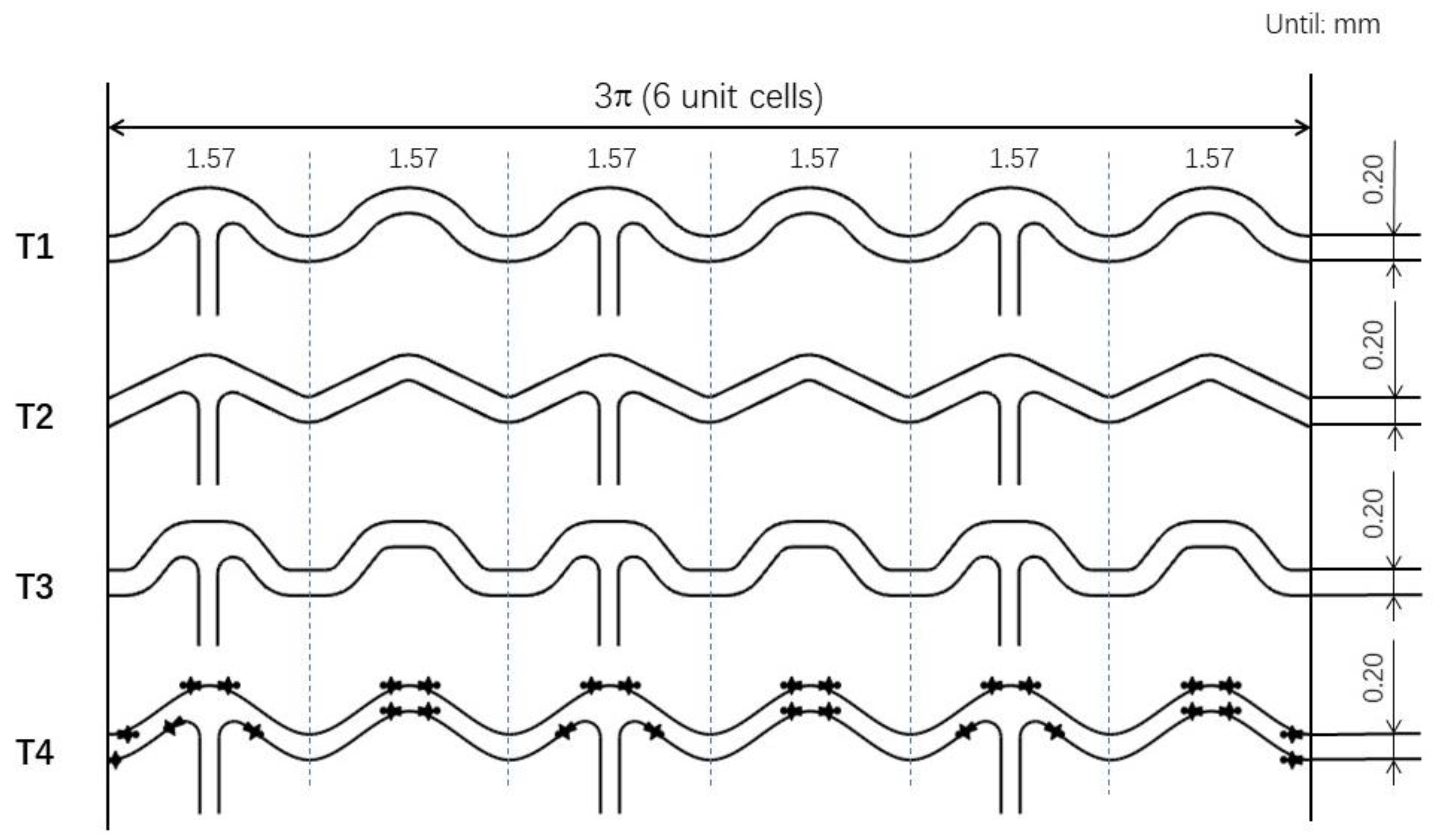
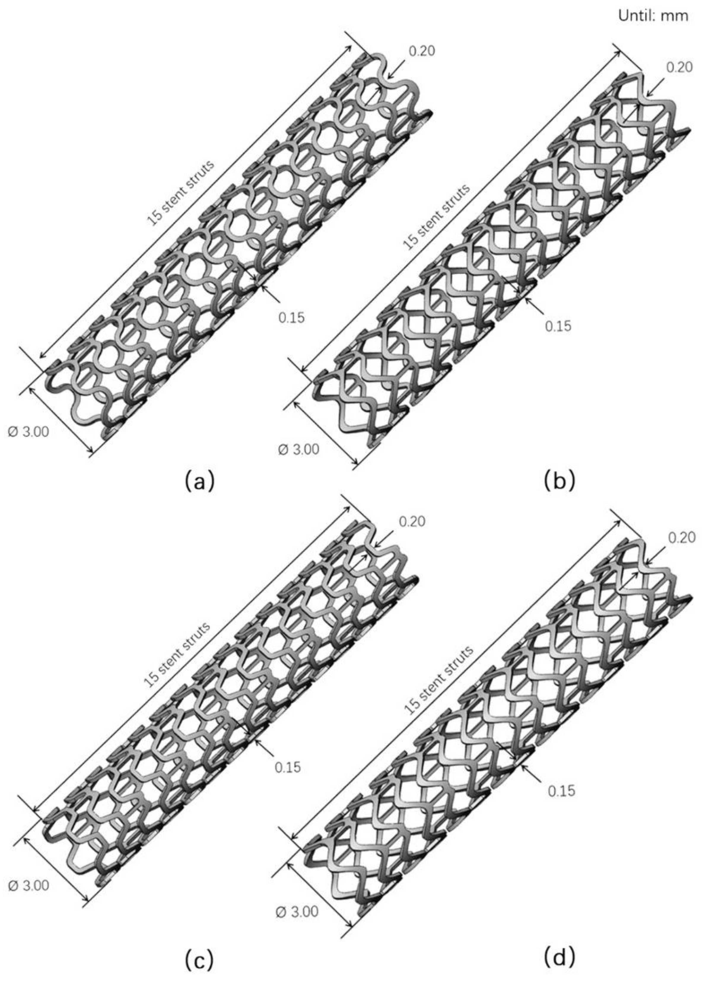
2.1. Models
2.2. Experimental Methods
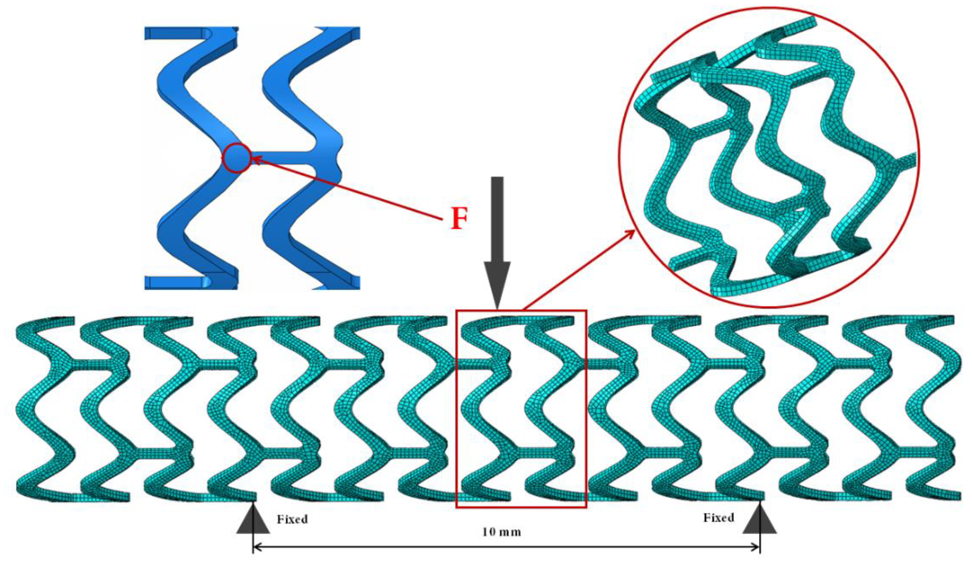
2.3. Numerical Simulation
3. Results
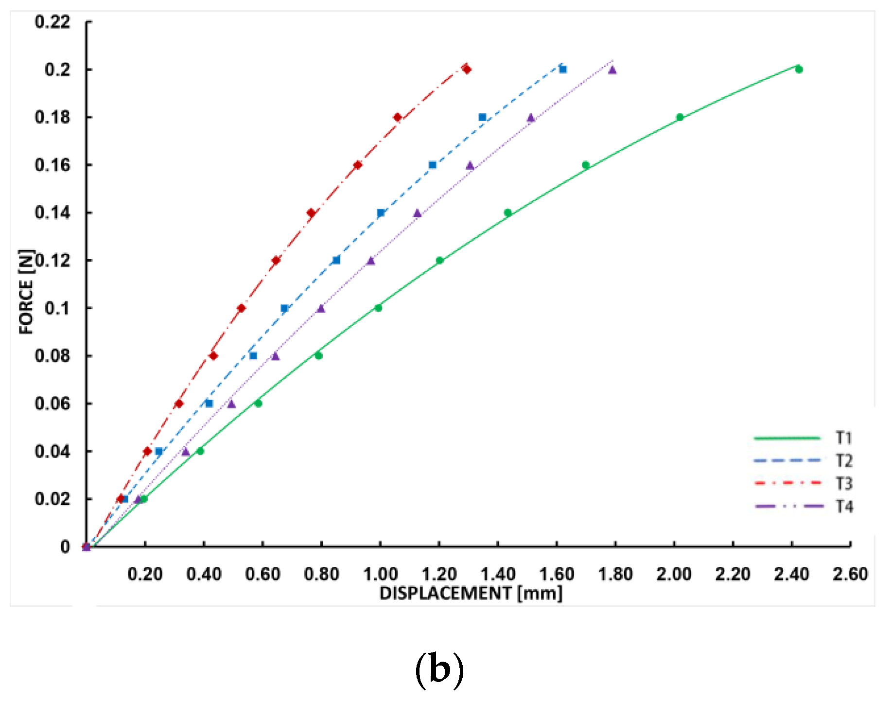
3.1. Bending Process Data
3.2. Stress Distribution
4. Discussion
5. Conclusions
Limitations of This Work
Author Contributions
Funding
Conflicts of Interest
References
- Foin, N.; Di Mario, C.; Francis, D.P.; Davies, J.E. Stent flexibility versus concertina effect: Mechanism of an unpleasant trade-off in stent design and its implications for stent selection in the cath-lab. Int. J. Cardiol. 2013, 164, 259–261. [Google Scholar] [CrossRef] [PubMed]
- Wu, W.; Yang, D.Z.; Qi, M.; Wang, W.Q. An FEA method to study flexibility of expanded coronary stents. J. Mater. Process Technol. 2006, 184, 447–450. [Google Scholar] [CrossRef]
- Shen, X.; Deng, Y.Q.; Ji, S.; Zhu, H.F.; Jiang, J.B.; Gu, L.X. Bending Analysis of Stented Coronary Artery: The Interaction Between Stent and Vessel. J. Mech. 2019, 35, 455–463. [Google Scholar] [CrossRef]
- Petrini, L.; Migliavacca, F.; Auricchio, F. Numerical investigation of the intravascular coronary stent flexibility. J. Biomech. 2004, 37, 495–501. [Google Scholar] [CrossRef] [PubMed]
- Ormiston, J.A.; Dixon, S.R.; Webster, M.W.; Ruygrok, P.N.; Stewart, J.T.; Minchington, I.; West, T. Stent longitudinal flexibility: A comparison of 13 stent designs before and after balloon expansion. Catheter. Cardiovasc. Interv. 2000, 50, 120–124. [Google Scholar] [CrossRef]
- Azaouzi, M.; Makradi, A.; Belouettar, S. Numerical investigations of the structural behavior of a balloon expandable stent design using finite element method. Comput. Mat. Sci. 2013, 72, 54–61. [Google Scholar] [CrossRef]
- Ju, F.; Xia, Z.; Zhou, C. Repeated unit cell (RUC) approach for pure bending analysis of coronary stents. Comput. Methods Biomech. Biomed. Eng. 2008, 11, 419–431. [Google Scholar] [CrossRef]
- Syaifudin, A.; Takeda, R.; Sasaki, K. Effect of Asymmetric Geometry on the Flexibility of Stent. J. Mech. Eng. Sci. 2017, 1, 1–7. [Google Scholar] [CrossRef] [Green Version]
- Bobel, A.C.; Petisco, S.; Sarasua, J.-R.; Wang, W.; McHugh, P.E. Computational Bench Testing to Evaluate the Short-Term Mechanical Performance of a Polymeric Stent. Cardiovasc. Eng. Technol. 2015, 6, 519–532. [Google Scholar] [CrossRef]
- Ginsberg, G.; Cope, C.; Shah, J.; Martin, T.; Carty, A.; Habecker, P.; Kaufmann, C.; Clerc, C.; Nuutinen, J.P.; Törmälä, P. In vivo evaluation of a new bioabsorbable self-expanding biliary stent. Gastrointest. Endosc. 2003, 58, 777–784. [Google Scholar] [CrossRef]
- Barragan, P.; Garitey, V.; Roquebert, P.O.; Fuseri, J.; Commeau, P.; Sainsous, J. Assessment of the trackability, flexibility, and conformability of coronary stents: A comparative analysis. Catheter. Cardiovasc. Interv. 2003, 59, 496–503. [Google Scholar] [CrossRef]
- Mori, K.; Saito, T. Effects of stent structure on stent flexibility measurements. Ann. Biomed. Eng. 2005, 3, 733. [Google Scholar] [CrossRef] [PubMed]
- Li, N.; Zhang, H.; Ouyang, H. Shape optimization of coronary artery stent based on a parametric model. Finite Elem. Anal. Des. 2009, 45, 468–475. [Google Scholar] [CrossRef]
- Shah, B.R. Longitudinal Stent Deformation at Aneurysm Site: Flexibility at the Expense of Longitudinal Integrity. J. Clin. Diagn. Res. 2017, 11, OD15–OD16. [Google Scholar] [CrossRef]
- Liu, Y.; Zhu, G.; Yang, H.; Wang, C.; Zhang, P.; Han, G. Bending behaviors of fully covered biodegradable polydioxanone biliary stent for human body by finite element method. J. Mech. Behav. Biomed. Mater. 2018, 77, 157–163. [Google Scholar] [CrossRef]
- McMahon, S.; Bertollo, N.; O’Cearbhaill, E.D.; Salber, J.; Pierucci, L.; Duffy, P.; Dürig, T.; Bi, V.; Wang, W. Bio-resorbable polymer stents: A review of material progress and prospects. Prog. Polym. Sci. 2018, 83, 79–96. [Google Scholar] [CrossRef]
- Chen, C.; Xiong, Y.; Jiang, W.; Wang, Y.; Wang, Z.; Chen, Y. Experimental and Numerical Simulation of Biodegradable Stents with Different Strut Geometries. Cardiovasc. Eng. Technol. 2020, 11, 36–46. [Google Scholar] [CrossRef]
- Abaqus, M. Version 6.13. Dassault Systems; Simulia Corporation: Waltham, MA, USA, 2013. [Google Scholar]
- Shen, X.; Zhu, H.; Jiang, J.; Deng, Y.; Ji, S. Multi-Objective Optimization Design of Balloon-Expandable Coronary Stent. Cardiovasc. Eng. Technol. 2019, 10, 10–21. [Google Scholar] [CrossRef]
- Alherz, A.I.; Tanweer, O.; Flamini, V. A numerical framework for the mechanical analysis of dual-layer stents in intracranial aneurysm treatment. J. Biomech. 2016, 49, 2420–2427. [Google Scholar] [CrossRef]
- Gyöngyösi, M.; Yang, P.; Khorsand, A.; Glogar, D. Longitudinal straightening effect of stents is an additional predictor for major adverse cardiac events. J. Am. Coll. Cardiol. 2000, 35, 1580–1589. [Google Scholar] [CrossRef] [Green Version]
- Szabadíts, P.; Puskás, Z.; Dobránszky, J. Flexibility and trackability of laser cut coronary stent systems. Act. Bioeng. Biomech. 2009, 11, 11. [Google Scholar]
- Morton, A.C.; Crossman, D.; Gunn, J. The influence of physical stent parameters upon restenosis. Patholog. Biol. 2004, 52, 196–205. [Google Scholar] [CrossRef] [PubMed]
- Finn, A.V.; Joner, M.; Nakazawa, G. The Pathological Correlates of newest Drug—Eluting Stent Thrombosis: Struts Coverage as a Marker of Endothelialization. Circulation 2007, 115, 2435–2441. [Google Scholar] [CrossRef] [PubMed] [Green Version]
- Guerra, A.J.; Ciurana, J. 3D-printed bioabsordable polycaprolactone stent: The effect of process parameters on its physical features. Mater. Des. 2018, 137, 430–437. [Google Scholar] [CrossRef]


© 2020 by the authors. Licensee MDPI, Basel, Switzerland. This article is an open access article distributed under the terms and conditions of the Creative Commons Attribution (CC BY) license (http://creativecommons.org/licenses/by/4.0/).
Share and Cite
Chen, C.; Xiong, Y.; Li, Z.; Chen, Y. Flexibility of Biodegradable Polymer Stents with Different Strut Geometries. Materials 2020, 13, 3332. https://doi.org/10.3390/ma13153332
Chen C, Xiong Y, Li Z, Chen Y. Flexibility of Biodegradable Polymer Stents with Different Strut Geometries. Materials. 2020; 13(15):3332. https://doi.org/10.3390/ma13153332
Chicago/Turabian StyleChen, Chong, Yan Xiong, Zhongyou Li, and Yu Chen. 2020. "Flexibility of Biodegradable Polymer Stents with Different Strut Geometries" Materials 13, no. 15: 3332. https://doi.org/10.3390/ma13153332
APA StyleChen, C., Xiong, Y., Li, Z., & Chen, Y. (2020). Flexibility of Biodegradable Polymer Stents with Different Strut Geometries. Materials, 13(15), 3332. https://doi.org/10.3390/ma13153332