High-Performance Multilayer Radiative Cooling Films Designed with Flexible Hybrid Optimization Strategy


Abstract
1. Introduction
2. Materials and Methods
2.1. The GA in the FHOS
2.2. The TM Method in the FHOS
2.3. The EV Function in the FHOS
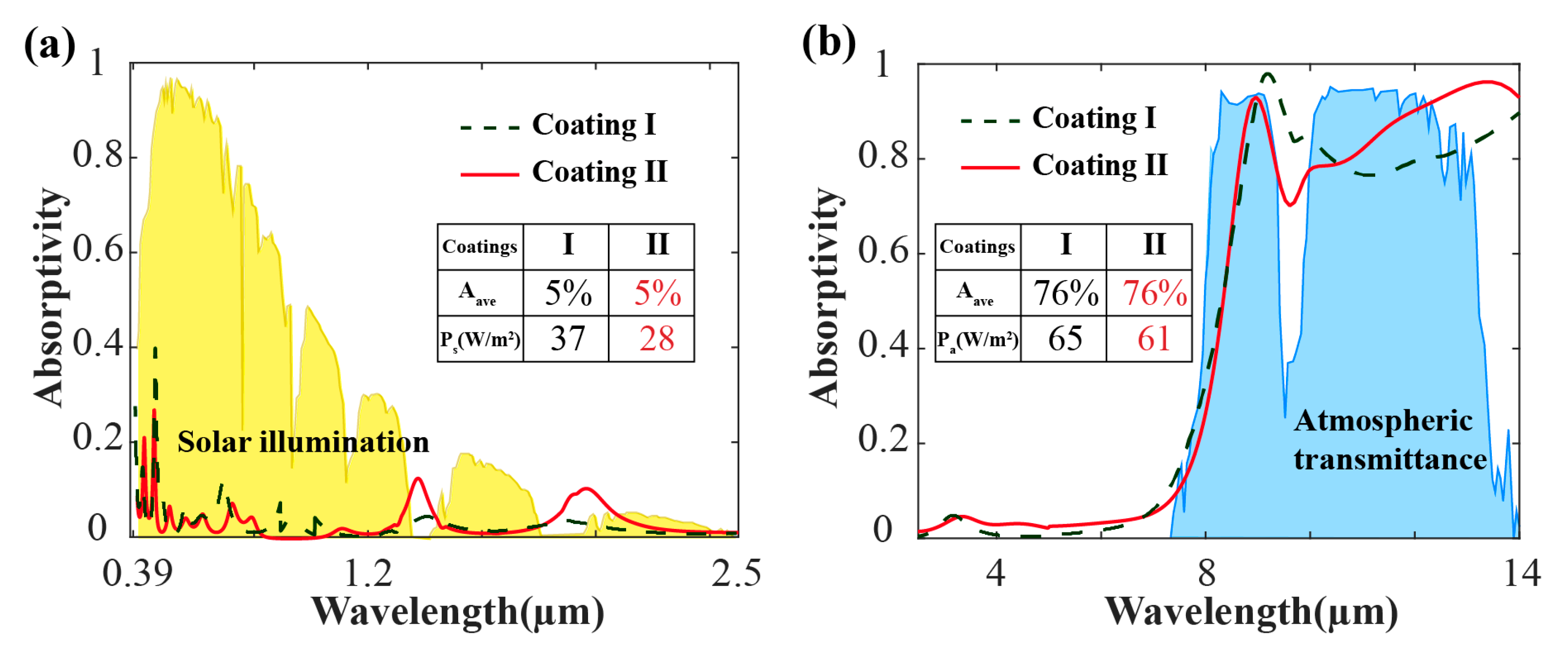
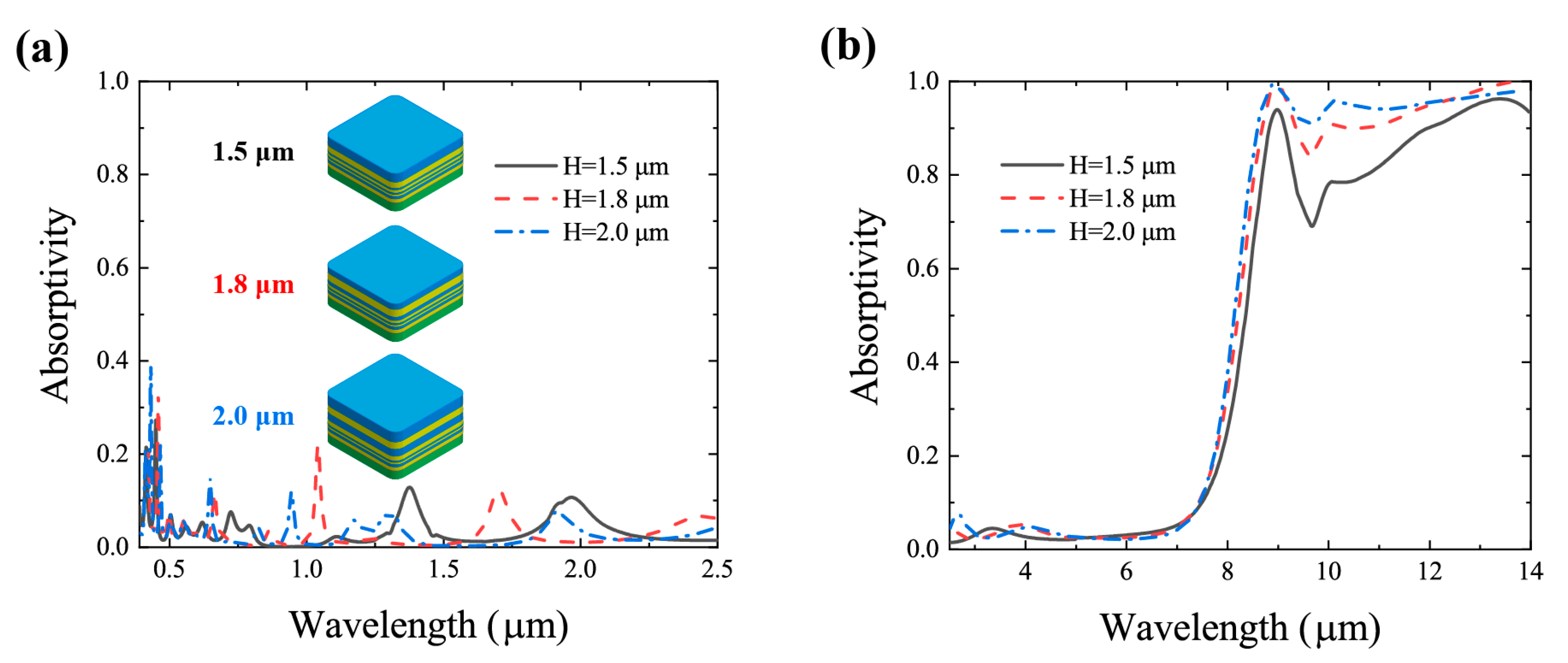
3. Results
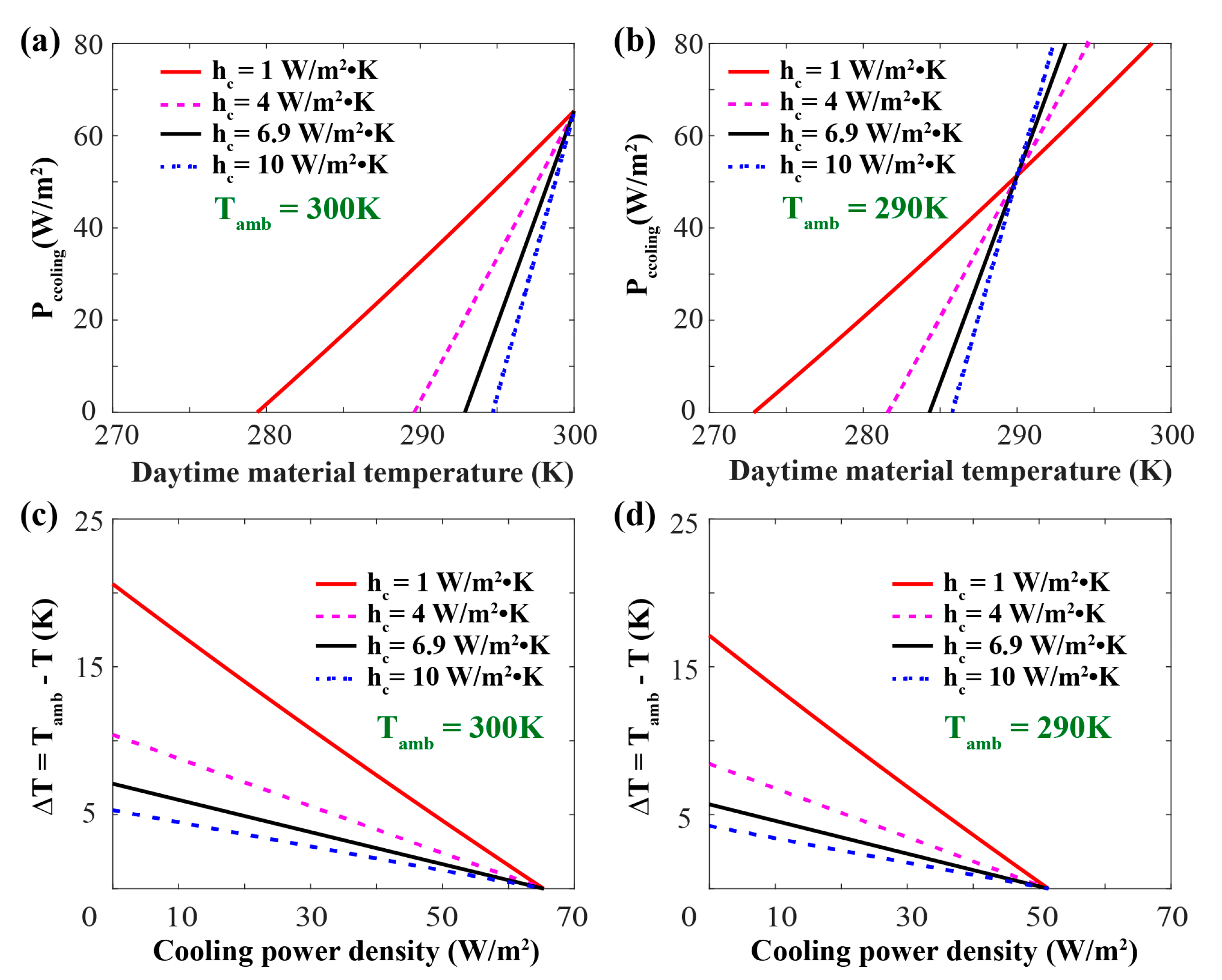
4. Discussion
5. Conclusions
Author Contributions
Funding
Conflicts of Interest
References
- Wang, Y.; Wang, A.; Zhai, J.; Tao, H.; Jiang, T.; Su, B.; Yang, J.; Wang, G.; Liu, Q.; Gao, C.; et al. Tens of thousands additional deaths annually in cities of China between 1.5 °C and 2.0 °C warming. Nat. Commun. 2019, 10, 3376. [Google Scholar] [CrossRef] [PubMed]
- Raman, A.P.; Anoma, M.A.; Zhu, L.; Rephaeli, E.; Fan, S. Passive radiative cooling below ambient air temperature under direct sunlight. Nature 2014, 515, 540–544. [Google Scholar] [CrossRef]
- Li, T.; Zhai, Y.; He, S.; Gan, W.; Wei, Z.; Heidarinejad, M.; Dalgo, D.; Mi, R.; Zhao, X.; Song, J.; et al. A radiative cooling structural material. Science 2019, 364, 760–763. [Google Scholar] [CrossRef] [PubMed]
- Mandal, J.; Fu, Y.; Overvig, A.C.; Jia, M.; Sun, K.; Shi, N.N.; Zhou, H.; Xiao, X.; Yu, N.; Yang, Y. Hierarchically porous polymer coatings for highly efficient passive daytime radiative cooling. Science 2018, 362, 315–319. [Google Scholar] [CrossRef] [PubMed]
- Zhai, Y.; Ma, Y.; David, S.N.; Zhao, D.; Lou, R.; Tan, G.; Yang, R.; Yin, X. Scalable-manufactured randomized glass-polymer hybrid metamaterial for daytime radiative cooling. Science 2017, 355, 1062–1066. [Google Scholar] [CrossRef]
- Leroy, A.; Bhatia, B.; Kelsall, C.C.; Castillejo-Cuberos, A.; Di Capua, H.M.; Zhao, L.; Zhang, L.; Guzman, A.M.; Wang, E.N. High-performance subambient radiative cooling enabled by optically selective and thermally insulating polyethylene aerogel. Sci. Adv. 2019, 5, eaat9480. [Google Scholar] [CrossRef]
- Zhu, L.X.; Raman, A.P.; Fan, S.H. Radiative cooling of solar absorbers using a visibly transparent photonic crystal thermal blackbody. Proc. Natl. Acad. Sci. USA 2015, 112, 12282–12287. [Google Scholar] [CrossRef]
- Granqvist, C.G.; Hjortsberg, A. Radiative cooling to low temperatures: General considerations and application to selectively emitting SiO films. J. Appl. Phys. 1981, 52, 4205–4220. [Google Scholar] [CrossRef]
- Eicker, U.; Dalibard, A. Photovoltaic–thermal collectors for night radiative cooling of buildings. Sol. Energy 2011, 85, 1322–1335. [Google Scholar] [CrossRef]
- Catalanotti, S.; Cuomo, V.; Piro, G.; Ruggi, D.; Silvestrini, V.; Troise, G. The radiative cooling of selective surfaces. Sol. Energy Mater. Sol. Cells 1975, 17, 83–89. [Google Scholar] [CrossRef]
- Chen, Z.; Zhu, L.; Raman, A.; Fan, S. Radiative cooling to deep sub-freezing temperatures through a 24-h day–night cycle. Nat. Commun. 2016, 7, 13729. [Google Scholar] [CrossRef] [PubMed]
- Kou, J.-l.; Jurado, Z.; Chen, Z.; Fan, S.; Minnich, A.J. Daytime radiative cooling using near-black infrared emitters. ACS Photonics 2017, 4, 626–630. [Google Scholar] [CrossRef]
- Bhatia, B.; Leroy, A.; Shen, Y.; Zhao, L.; Gianello, M.; Li, D.; Gu, T.; Hu, J.; Soljacic, M.; Wang, E.N. Passive directional sub-ambient daytime radiative cooling. Nat. Commun. 2018, 9, 5001. [Google Scholar] [CrossRef]
- Rephaeli, E.; Raman, A.; Fan, S.H. Ultrabroadband photonic structures to achieve high-performance daytime radiative cooling. Nano Lett. 2013, 13, 1457–1461. [Google Scholar] [CrossRef]
- Zhou, L.; Song, H.; Liang, J.; Singer, M.; Zhou, M.; Stegenburgs, E.; Zhang, N.; Xu, C.; Ng, T.; Yu, Z. A polydimethylsiloxane-coated metal structure for all-day radiative cooling. Nat. Sustain. 2019, 2, 718–724. [Google Scholar] [CrossRef]
- Zhao, D.L.; Aili, A.; Zhai, Y.; Xu, S.Y.; Tan, G.; Yin, X.B.; Yang, R.G. Radiative sky cooling: Fundamental principles, materials, and applications. Appl. Phys. Rev. 2019, 6, 021306. [Google Scholar] [CrossRef]
- Guo, J.; Wang, T.; Quan, B.; Zhao, H.; Gu, C.; Li, J.; Wang, X.; Situ, G.; Zhang, Y. Polarization multiplexing for double images display. Opto-Electron. Adv. 2019, 2, 180029. [Google Scholar] [CrossRef]
- Huang, Y.; Luo, J.; Pu, M.; Guo, Y.; Zhao, Z.; Ma, X.; Li, X.; Luo, X. Catenary electromagnetics for ultra-broadband lightweight absorbers and large-scale flat antennas. Adv. Sci. 2019, 6, 1801691. [Google Scholar] [CrossRef]
- Ma, X.; Pu, M.; Li, X.; Guo, Y.; Luo, X. All-metallic wide-angle metasurfaces for multifunctional polarization manipulation. Opto-Electron. Adv. 2019, 2, 180023. [Google Scholar] [CrossRef]
- Xie, X.; Liu, K.; Pu, M.; Ma, X.; Li, X.; Guo, Y.; Zhang, F.; Luo, X. All-metallic geometric metasurfaces for broadband and high-efficiency wavefront manipulation. Nanophotonics 2019. [Google Scholar] [CrossRef]
- Pu, M.; Li, X.; Ma, X.; Wang, Y.; Zhao, Z.; Wang, C.; Hu, C.; Gao, P.; Huang, C.; Ren, H. Catenary optics for achromatic generation of perfect optical angular momentum. Sci. Adv. 2015, 1, e1500396. [Google Scholar] [CrossRef] [PubMed]
- Xie, X.; Li, X.; Pu, M.; Ma, X.; Liu, K.; Guo, Y.; Luo, X. Plasmonic metasurfaces for simultaneous thermal infrared invisibility and holographic illusion. Adv. Funct. Mater. 2018, 28, 1706673. [Google Scholar] [CrossRef]
- Feng, X.; Xie, X.; Pu, M.; Ma, X.; Guo, Y.; Li, X.; Luo, X. Hierarchical metamaterials for laser-infrared-microwave compatible camouflage. Opt. Express 2020, 28, 9445–9453. [Google Scholar] [CrossRef] [PubMed]
- Gerislioglu, B.; Dong, L.; Ahmadivand, A.; Hu, H.; Nordlander, P.; Halas, N.J. Monolithic metal dimer-on-film structure: New plasmonic properties introduced by the underlying metal. Nano Lett. 2020, 20, 2087–2093. [Google Scholar] [CrossRef] [PubMed]
- Cheng, C.H.; Shen, C.C.; Kao, H.Y.; Hsieh, D.H.; Wang, H.Y.; Yeh, Y.W.; Lu, Y.T.; Chen, S.W.H.; Tsai, C.T.; Chi, Y.C.; et al. [Opto-Electron Adv, 2018, 1 (3)] 850/940-nm VCSEL for optical communication and 3D sensing. Opto-Electron. Rep. 2018, 2, a201903002. [Google Scholar]
- Tan, F.Z.; Lyu, W.M.; Chen, S.Y.; Liu, Z.Y.; Yu, C.Y. Contactless vital signs monitoring based on few-mode and multi-core fibers. Opto-Electron. Adv. 2020, 3, 190034. [Google Scholar] [CrossRef]
- Bao, H.; Yan, C.; Wang, B.; Fang, X.; Zhao, C.; Ruan, X. Double-layer nanoparticle-based coatings for efficient terrestrial radiative cooling. Sol. Energy Mater. Sol. Cells 2017, 168, 78–84. [Google Scholar] [CrossRef]
- Zhao, B.; Hu, M.; Ao, X.; Chen, N.; Pei, G. Radiative cooling: A review of fundamentals, materials, applications, and prospects. Appl. Energy 2019, 236, 489–513. [Google Scholar] [CrossRef]
- Zhao, B.; Hu, M.; Ao, X.; Xuan, Q.; Pei, G. Comprehensive photonic approach for diurnal photovoltaic and nocturnal radiative cooling. Sol. Energy Mater. Sol. Cells 2018, 178, 266–272. [Google Scholar] [CrossRef]
- Yao, K.; Ma, H.; Huang, M.; Zhao, H.; Zhao, J.; Li, Y.; Dou, S.; Zhan, Y. Near-perfect selective photonic crystal emitter with nanoscale layers for daytime radiative cooling. ACS Appl. Nano Mater. 2019, 2, 5512–5519. [Google Scholar] [CrossRef]
- Harik, G.R.; Lobo, F.G.; Goldberg, D.E. The compact genetic algorithm. IEEE Trans. Evol. Comput. 1999, 3, 287–297. [Google Scholar] [CrossRef]
- Whitley, D. A genetic algorithm tutorial. Stat. Comput. 1994, 4, 65–85. [Google Scholar]
- Bossard, J.A.; Lin, L.; Yun, S.; Liu, L.; Werner, D.H.; Mayer, T.S. Near-ideal optical metamaterial absorbers with super-octave bandwidth. ACS Nano 2014, 8, 1517–1524. [Google Scholar] [CrossRef] [PubMed]
- Zhan, T.; Shi, X.; Dai, Y.; Liu, X.; Zi, J. Transfer matrix method for optics in graphene layers. J. Phys. Condens. Matter 2013, 25, 215301. [Google Scholar] [CrossRef] [PubMed]
- Palik, E.D. Handbook of Optical Constants of Solids; Academic Press: Orlando, FL, USA, 1985. [Google Scholar]
- Huang, Y.; Pu, M.; Gao, P.; Zhao, Z.; Li, X.; Ma, X.; Luo, X. Ultra-broadband large-scale infrared perfect absorber with optical transparency. Appl. Phys. Express 2017, 10, 112601. [Google Scholar] [CrossRef]
- Rodríguez-de Marcos, L.V.; Larruquert, J.I.; Méndez, J.A.; Aznárez, J.A. Self-consistent optical constants of MgF2, LaF3, and CeF3 films. Opt. Mater. Express 2017, 7, 989–1006. [Google Scholar] [CrossRef]
- Kischkat, J.; Peters, S.; Gruska, B.; Semtsiv, M.; Chashnikova, M.; Klinkmüller, M.; Fedosenko, O.; Machulik, S.; Aleksandrova, A.; Monastyrskyi, G.; et al. Mid-infrared optical properties of thin films of aluminum oxide, titanium dioxide, silicon dioxide, aluminum nitride, and silicon nitride. Appl. Opt. 2012, 51, 6789–6798. [Google Scholar] [CrossRef]
- Luke, K.; Okawachi, Y.; Lamont, M.R.E.; Gaeta, A.L.; Lipson, M. Broadband mid-infrared frequency comb generation in a Si3N4 microresonator. Opt. Lett. 2015, 40, 4823–4826. [Google Scholar] [CrossRef]
- Zhou, S.; Liu, W.; Cai, C.; Liu, H. Comparative investigation of infrared optical absorption properties of silicon oxide, oxynitride and nitride films. In Proceedings of the Seventh International Conference on Thin Film Physics and Applications, Shanghai, China, 24–27 September 2010; p. 7995. [Google Scholar]
- Jeong, S.Y.; Tso, C.Y.; Ha, J.; Wong, Y.M.; Chao, C.Y.H.; Huang, B.; Qiu, H. Field investigation of a photonic multi-layered TiO2 passive radiative cooler in sub-tropical climate. Renew. Energy 2020, 146, 44–55. [Google Scholar] [CrossRef]
- He, Z.; Li, Y.; Xue, X.; Yang, Z.; Qin, J.; Feng, Y.; Zhang, W.; Xu, L. Generic method for creating waterborne coatings with sub-ambient daytime cooling–Part II: Cooling effect under real working conditions and key physical properties. Sol. Energy Mater. Sol. Cells 2020, 204, 110220. [Google Scholar] [CrossRef]


| Number of Layers | Layer = 9 | Total Thickness | H = 1.495 μm | ||||||
|---|---|---|---|---|---|---|---|---|---|
| Layer—i | 1 | 2 | 3 | 4 | 5 | 6 | 7 | 8 | 9 |
| Material | silver | MgF2 | Si3N4 | MgF2 | Si3N4 | MgF2 | Si3N4 | MgF2 | Si3N4 |
| Ratio—a | 5.35% | 5.55% | 11.04% | 11.10% | 8.16% | 9.56% | 8.23% | 31.24% | 9.77% |
| h-I/nm | 80 | 165 | 166 | 122 | 143 | 123 | 467 | 146 | 83 |
| h-II /nm | 80 | 83 | 165 | 166 | 122 | 143 | 123 | 467 | 146 |
© 2020 by the authors. Licensee MDPI, Basel, Switzerland. This article is an open access article distributed under the terms and conditions of the Creative Commons Attribution (CC BY) license (http://creativecommons.org/licenses/by/4.0/).
Share and Cite
You, P.; Li, X.; Huang, Y.; Ma, X.; Pu, M.; Guo, Y.; Luo, X. High-Performance Multilayer Radiative Cooling Films Designed with Flexible Hybrid Optimization Strategy. Materials 2020, 13, 2885. https://doi.org/10.3390/ma13132885
You P, Li X, Huang Y, Ma X, Pu M, Guo Y, Luo X. High-Performance Multilayer Radiative Cooling Films Designed with Flexible Hybrid Optimization Strategy. Materials. 2020; 13(13):2885. https://doi.org/10.3390/ma13132885
Chicago/Turabian StyleYou, Peng, Xiong Li, Yijia Huang, Xiaoliang Ma, Mingbo Pu, Yinghui Guo, and Xiangang Luo. 2020. "High-Performance Multilayer Radiative Cooling Films Designed with Flexible Hybrid Optimization Strategy" Materials 13, no. 13: 2885. https://doi.org/10.3390/ma13132885
APA StyleYou, P., Li, X., Huang, Y., Ma, X., Pu, M., Guo, Y., & Luo, X. (2020). High-Performance Multilayer Radiative Cooling Films Designed with Flexible Hybrid Optimization Strategy. Materials, 13(13), 2885. https://doi.org/10.3390/ma13132885