Wear Behavior of Ductile Iron Wheel Material Used for Rail-Transit Vehicles under Dry Sliding Conditions

Abstract
:1. Introduction
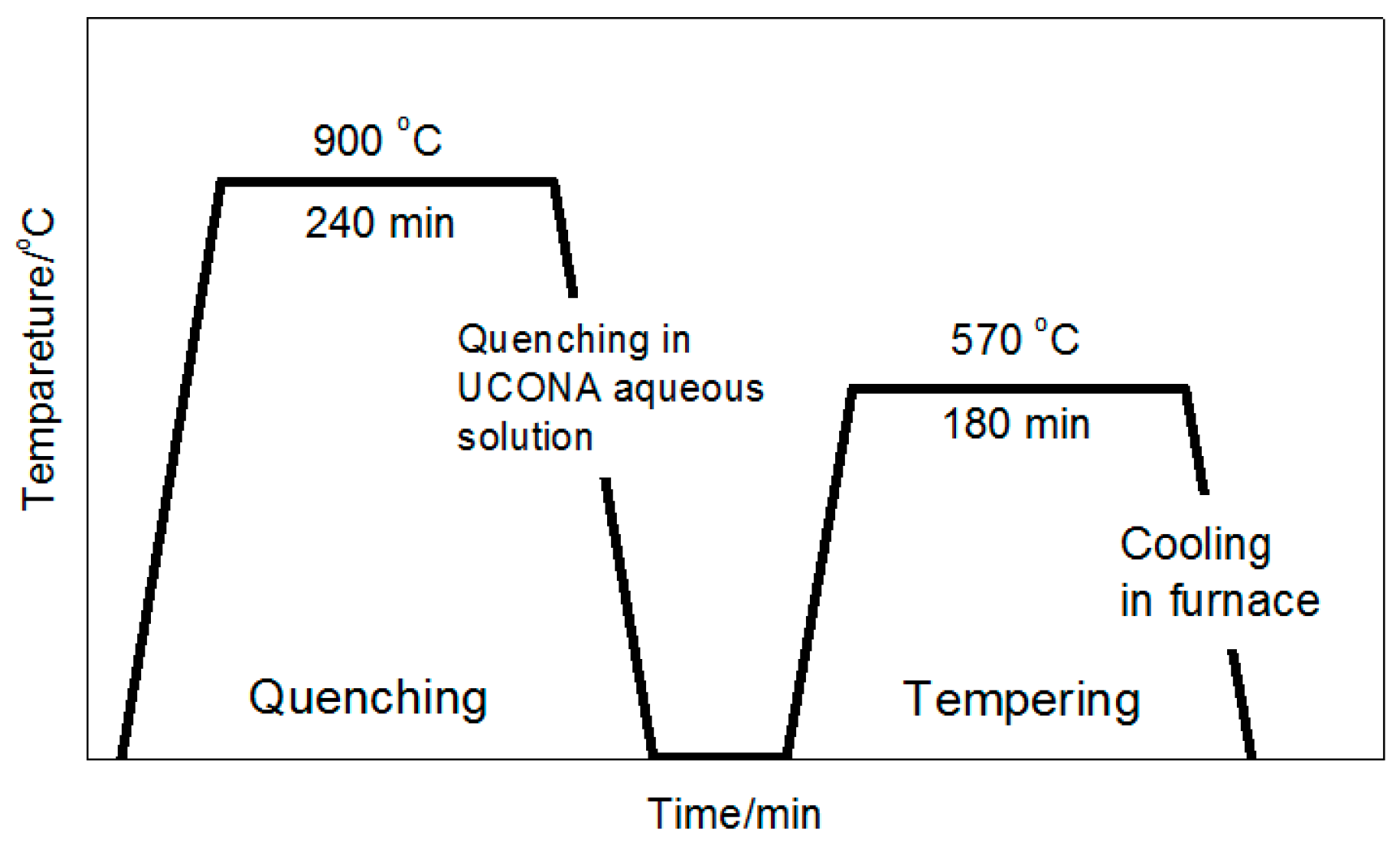
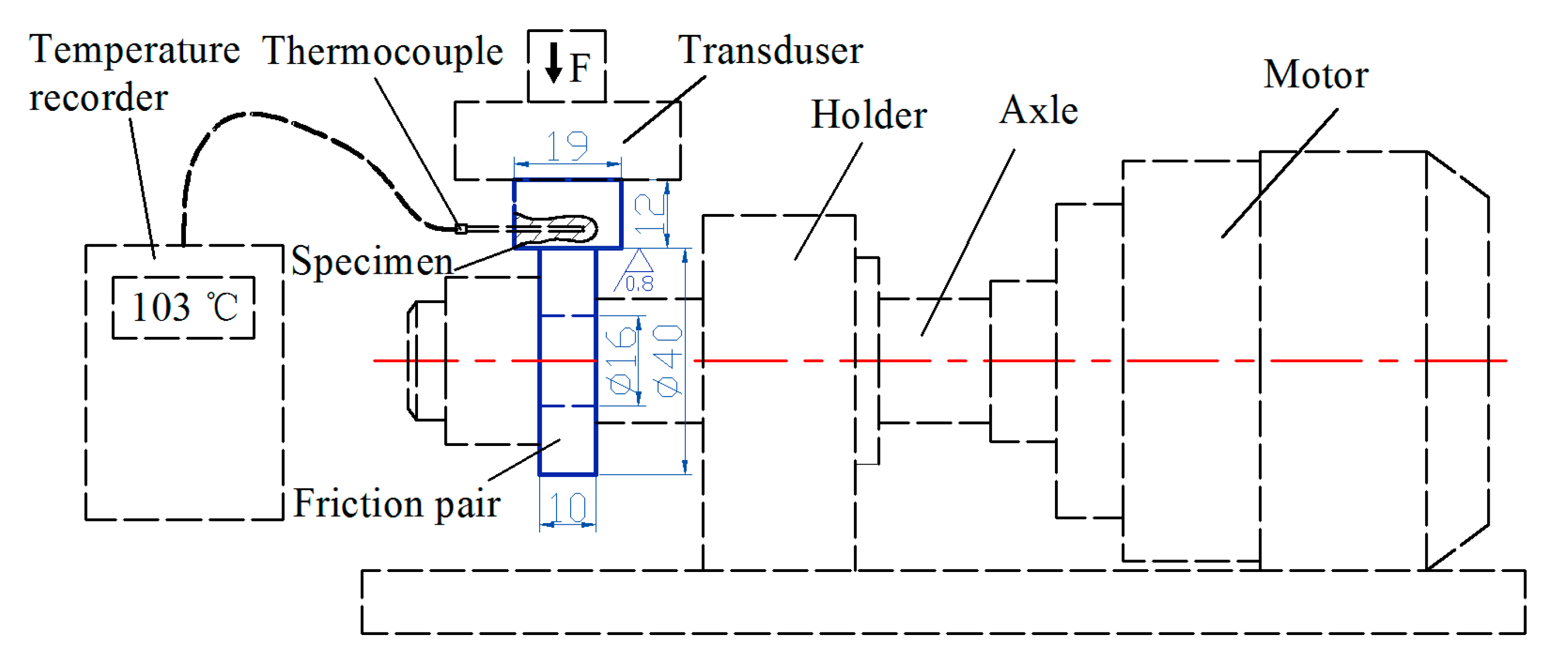
2. Experimental
3. Results and Discussion
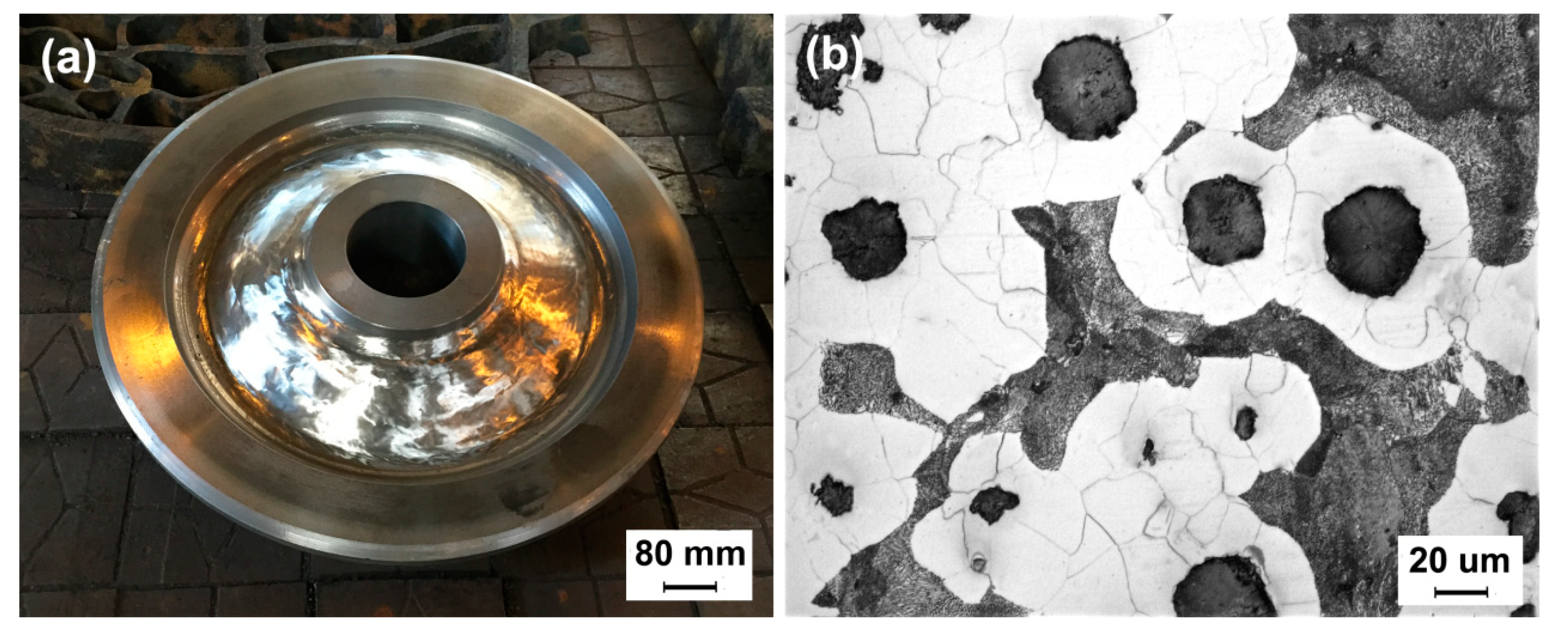
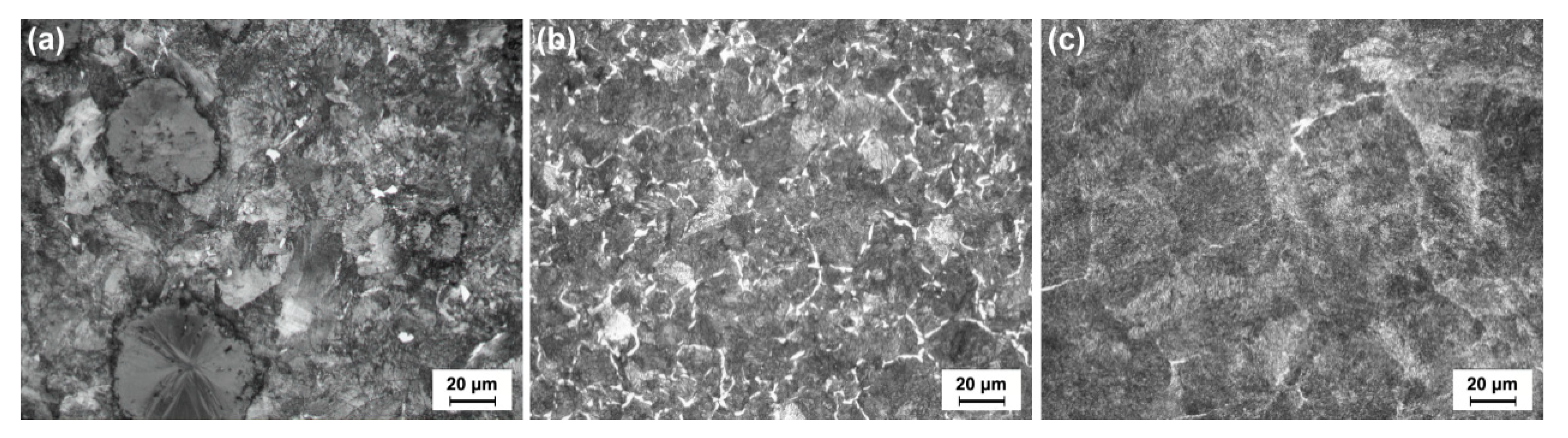
3.1. Microstructure and Mechanical Property
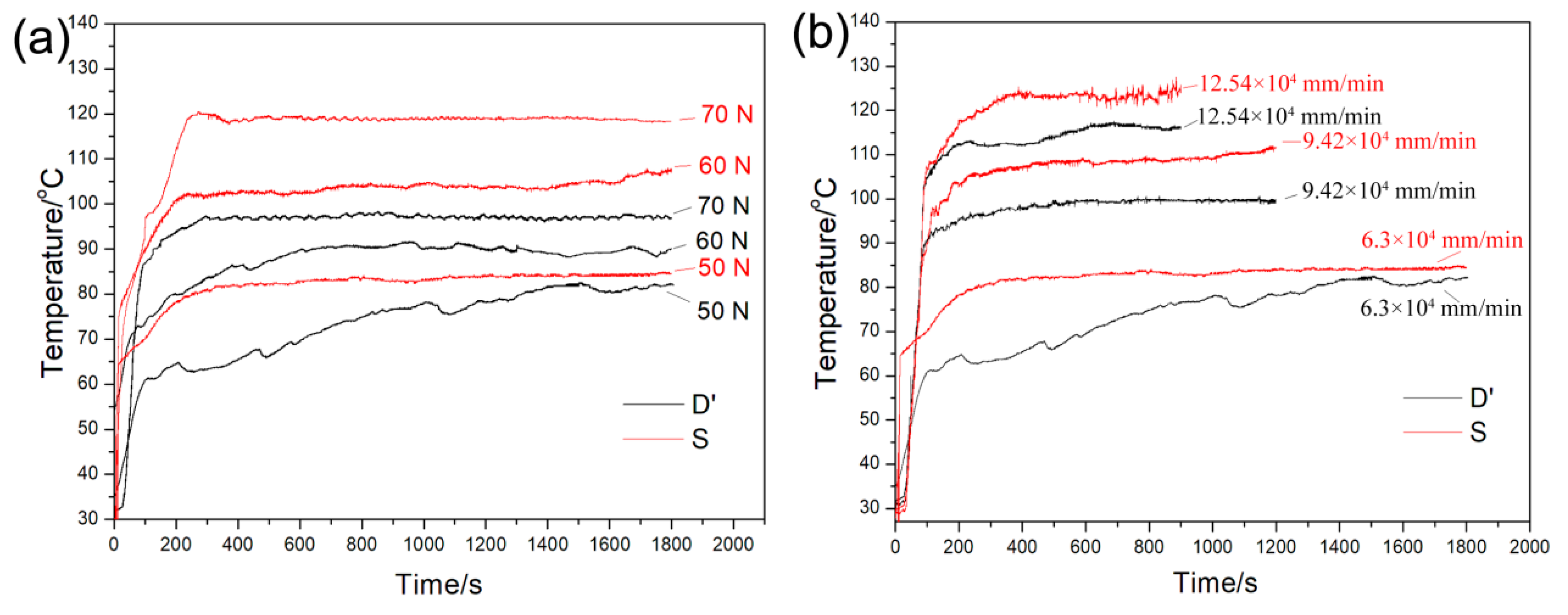
3.2. Thermal Property
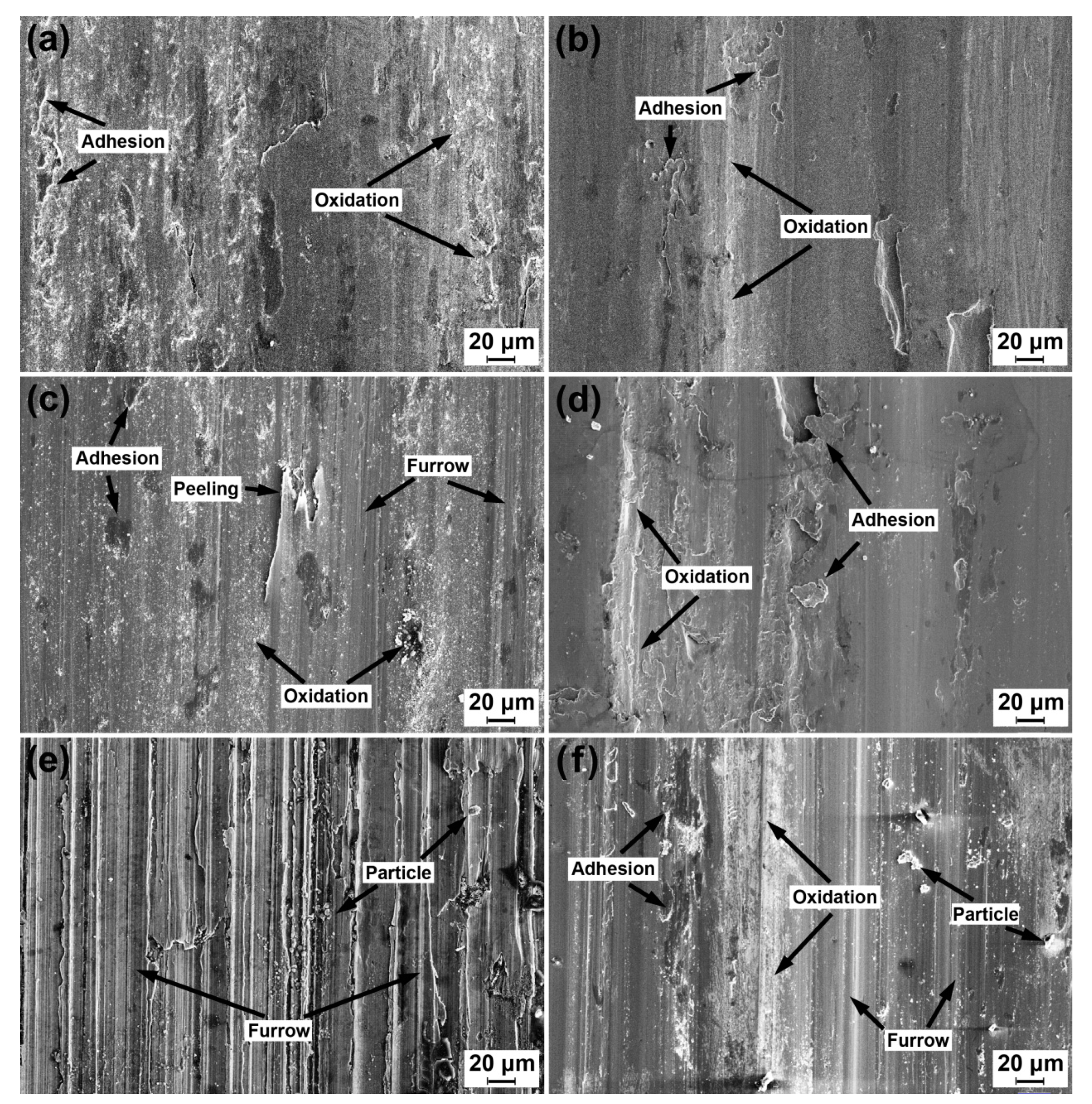
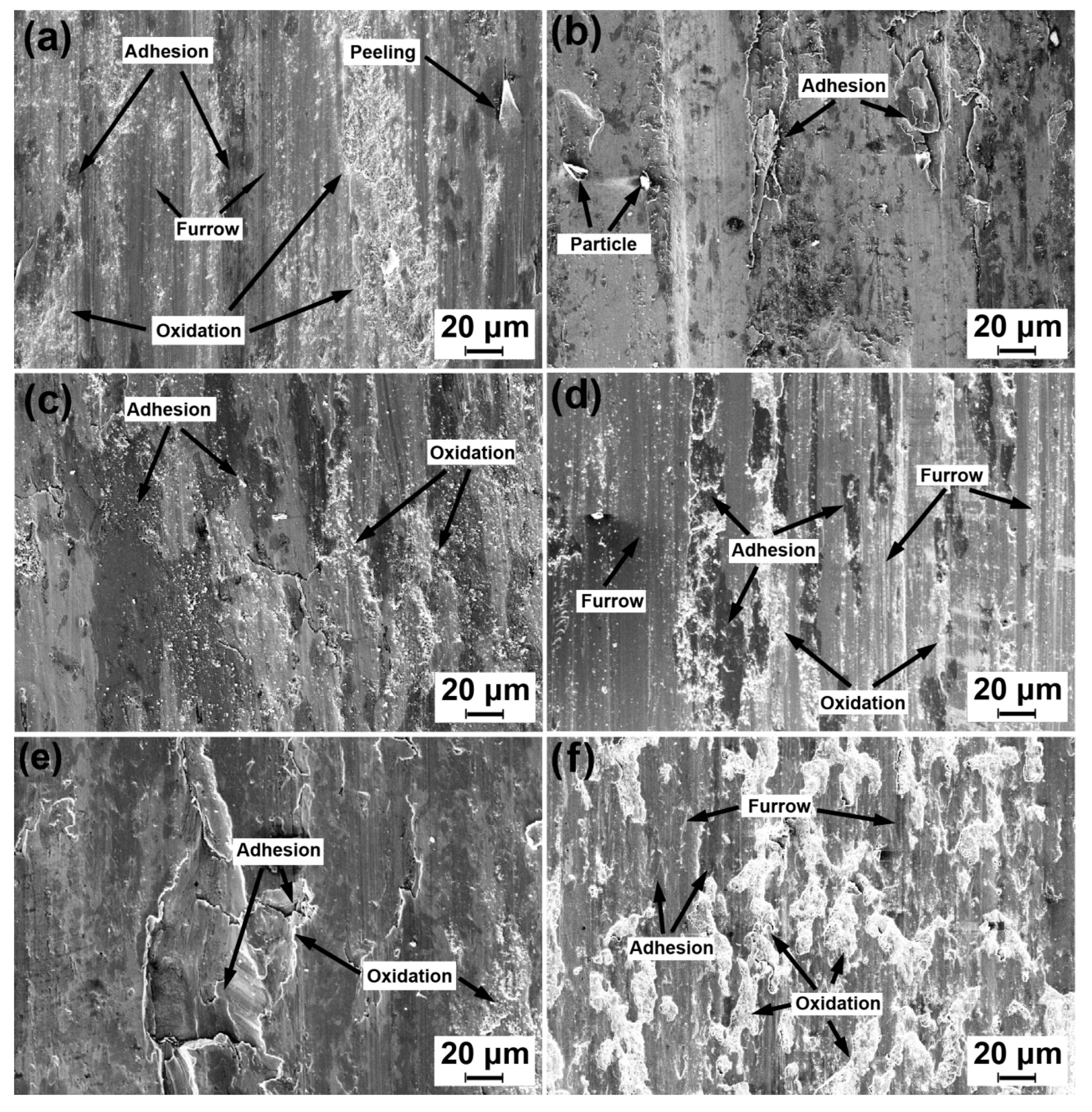
3.3. Worn-Surface Analysis
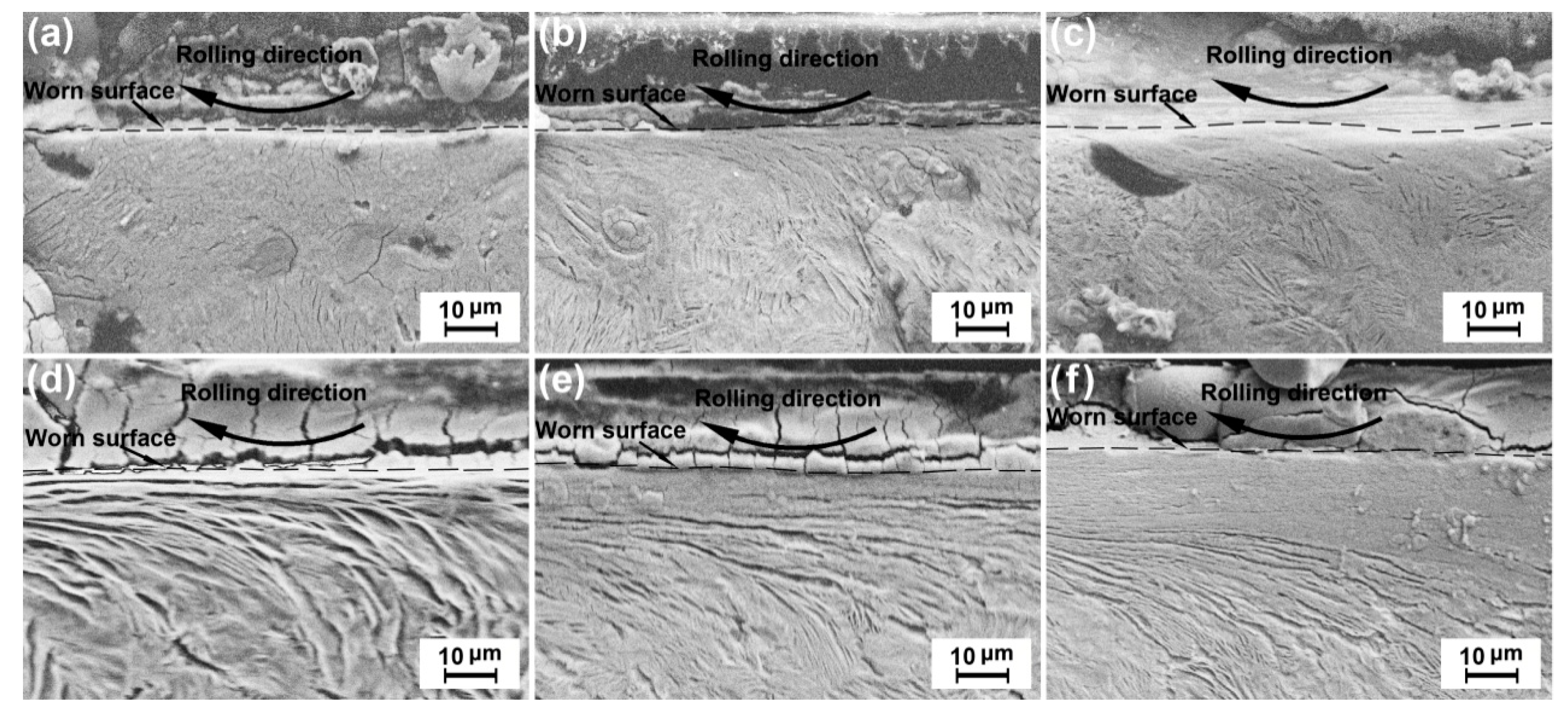
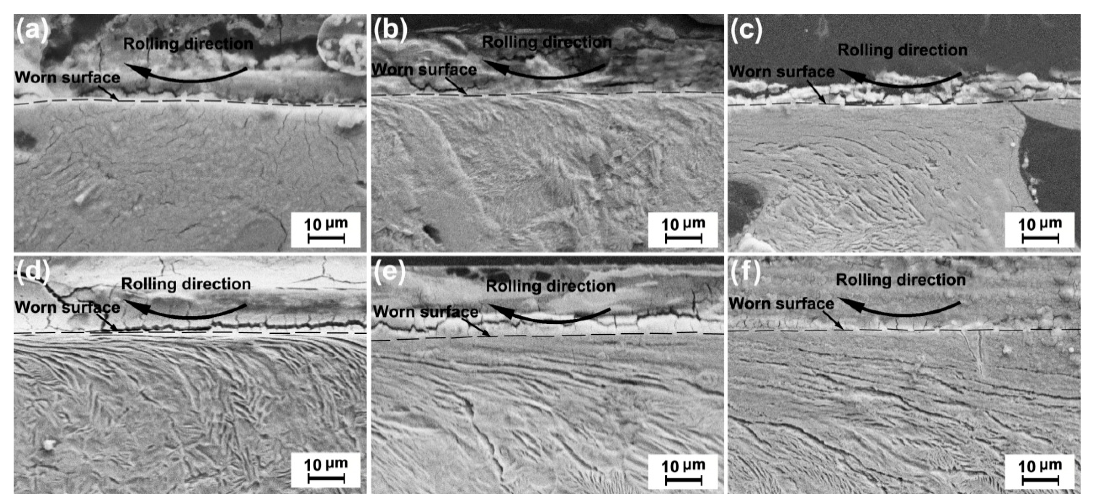
3.4. Plastic-Deformation Behavior
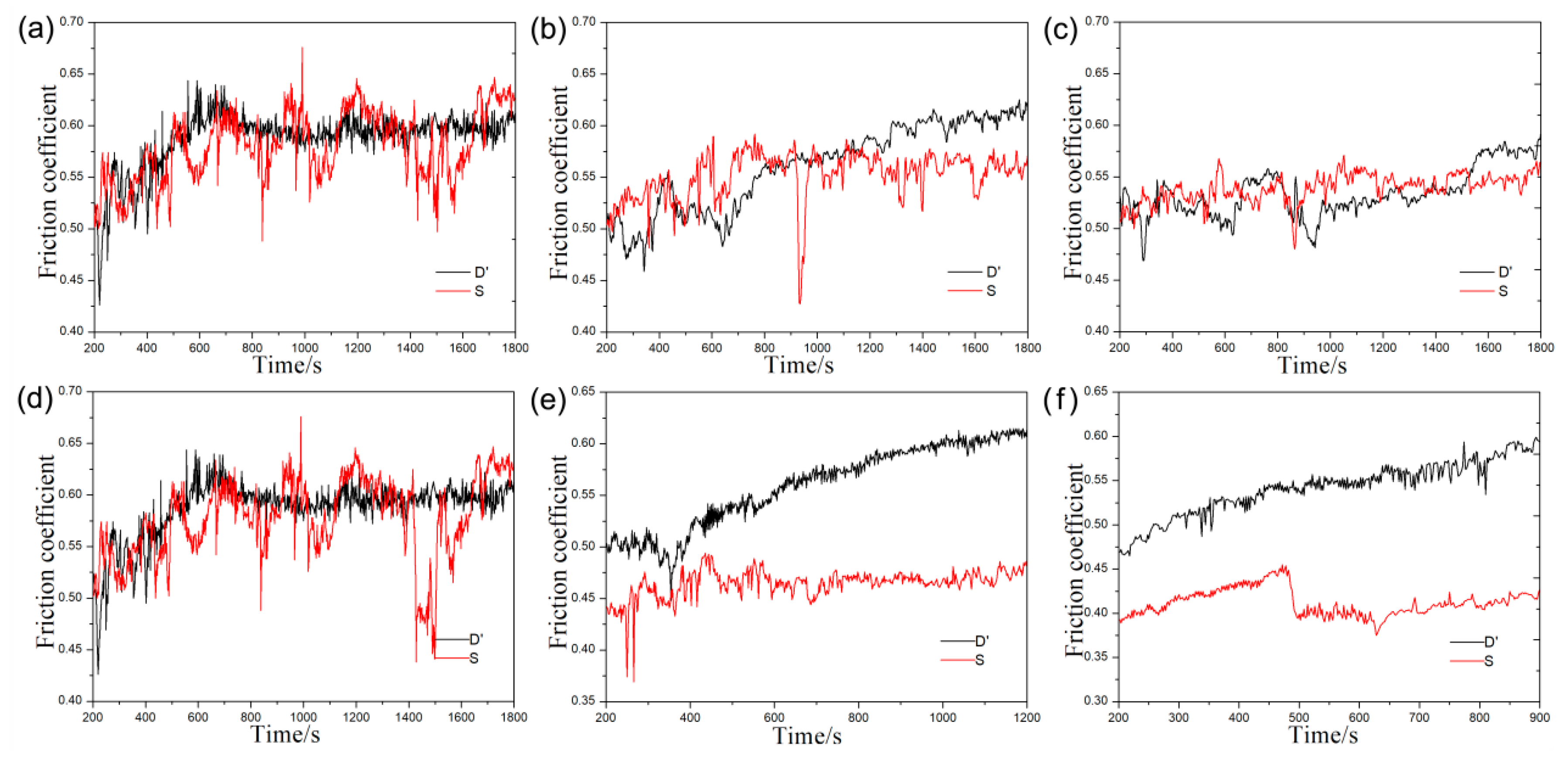
3.5. Friction Coefficient
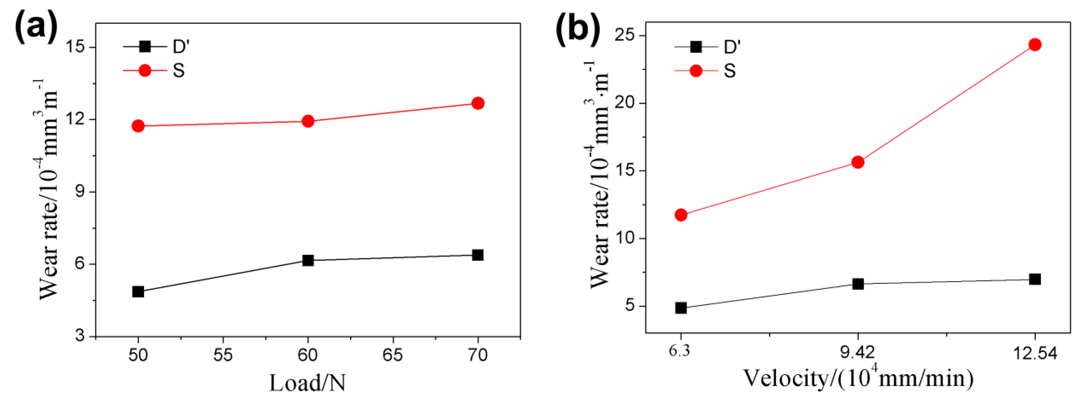
3.6. Wear Rate
4. Conclusions
Author Contributions
Funding
Conflicts of Interest
References
- Luo, R.; Shi, H.L.; Teng, W.X.; Song, C.Y. Prediction of wheel profile wear and vehicle dynamics evolution considering stochastic parameters for high-speed train. Wear 2017, 392, 126–138. [Google Scholar] [CrossRef]
- Faccoli, M.; Ghidini, A.; Mazzu’, A. Experimental and numerical investigation of the thermal effects on railway wheels for shoe-braked high-speed train applications. Metall. Mater. Trans. 2018, 49, 4544–4554. [Google Scholar] [CrossRef]
- Tao, G.Q.; Wen, Z.F.; Liang, X.R.; Ren, D.X.; Jin, X.S. An investigation into the mechanism of the out-of-round wheels of metro train and its mitigation measures. Veh. Syst. Dyn. 2018, 57, 1–16. [Google Scholar] [CrossRef]
- Ma, Y.; Pan, T.; Jiang, B.; Cui, Y.H.; Su, H.; Peng, Y. Study of the effect of sulfur contents on fracture toughness of railway wheel steels for high speed train. Acta Metall. Sin. 2011, 47, 978–983. [Google Scholar] [CrossRef]
- Xu, C.; Sun, J.H.; Liu, Z.; Zhang, G.J. Dynamic tread wear measurement method for train wheels against vibrations. Appl. Opt. 2015, 54, 5270–5280. [Google Scholar] [CrossRef]
- Hyde, P.; Defossez, F.; Ulianov, C. Development and testing of an automatic remote condition monitoring system for train wheels. Intell. Transp. Syst. Iet 2016, 10, 32–40. [Google Scholar] [CrossRef]
- Hervas, I.; Bettaieb, M.B.; Thuault, A.; Eric, H. Graphite nodule morphology as an indicator of the local complex strain state in ductile cast iron. Mater. Des. 2013, 52, 524–532. [Google Scholar] [CrossRef]
- Murcia, S.C.; Ossa, E.A.; Celentano, D.J. Nodule evolution of ductile cast iron during solidification. Metall. Materials Trans. B 2014, 45, 707–718. [Google Scholar] [CrossRef]
- Cai, Q.Z.; Wei, B.K. Recent development of ductile cast iron production technology in China. China Foundry 2008, 5, 82–91. [Google Scholar]
- Kumar, R.; Behera, R.K.; Sen, S. Effect of tempering temperature and time on strength and hardness of ductile cast iron. In Proceedings of the 4th National Conference on Processing and Characterization of Materials, New Delhi, India, 3 April 2015; pp. 751–759. [Google Scholar]
- Ayday, A.; Durman, M. The Evolution of microstructure for ductile iron treated under different thermal cycles using electrolytic plasma treatment. Acta Phys. Pol. 2014, 125, 577–578. [Google Scholar] [CrossRef]
- Qi, X.B.; Zhu, S.G.; Ding, H.; Xu, M.K. Theoretical and experimental analysis of electric contact surface hardening of ductile iron. Appl. Surf. Sci. 2014, 288, 591–598. [Google Scholar] [CrossRef]
- Vedel-Smith, N.K.; Rasmussen, J.; Tiedje, N.S. Thermal distortion of disc-shaped ductile iron castings in vertically parted moulds. J. Mater. Process. Tech. 2015, 217, 262–271. [Google Scholar] [CrossRef]
- Kruthiventi, S.; Basavakumar, K.G.; Nambala, S.; Subramanyacharyulu, G. Influence of heat treatment on microstructural and mechanical properties of nodular cast iron. J. Inst. Eng. 2014, 95, 75–79. [Google Scholar] [CrossRef]
- Sahin, Y.; Kilicli, V.; Ozer, M.; Mehmet, E. Comparison of abrasive wear behavior of ductile iron with different dual matrix structures. Wear 2010, 268, 153–165. [Google Scholar] [CrossRef]
- Li, J.; Xiao, X.S.; Xu, Y.L. Austempered ductile iron alloy for urban rail transit wheels. Patent CN 105543642, 29 August 2016. [Google Scholar]
- Abedi, H.R.; Fareghi, A.; Saghafian, H.; Kheirandish, S.H. Sliding wear behavior of a ferritic–pearlitic ductile cast iron with different nodule count. Wear 2010, 268, 622–628. [Google Scholar] [CrossRef]
- Ozgur, C.; Hayrettin, A.; Sabri Kayali, E.; Sabri, K.; Huseyin, C. High temperature abrasive wear behavior of an as-cast ductile iron. Wear 2005, 258, 189–193. [Google Scholar] [CrossRef]
- Sahin, Y.; Erdogan, M.; Cerah, M. Effect of martensite volume fraction and tempering time on abrasive wear of ferritic ductile iron with dual matrix. Wear 2008, 265, 196–202. [Google Scholar] [CrossRef]
- Podgornik, B.; Vizintin, J.; Thorbjornsson, I.; Johannesson, B.; Thorgrimsson, J.T.; Martinez Celis, M.; Valle, N. Improvement of ductile iron wear resistance through local surface reinforcement. Wear 2012, 274–275, 267–273. [Google Scholar] [CrossRef]
- Vicente, F.S.; Guillamón, M.P. Use of the fatigue index to study rolling contact wear. Wear 2019, 436, 1–9. [Google Scholar] [CrossRef]
- Zhou, Y.; Peng, J.F.; Wang, W.J.; Jin, X.S.; Zhu, M.H. Slippage effect on rolling contact wear and damage behavior of pearlitic steels. Wear 2016, 362, 362–363. [Google Scholar] [CrossRef]
- Kang, S. A study of friction and wear characteristics of copper- and iron-based sintered materials. Wear 1993, 162–164, 1123–1128. [Google Scholar] [CrossRef]
- Kubo, S.; Kato, K. Effect of arc discharge on the wear rate and wear mode transition of a copper-impregnated metallized carbon contact strip sliding against a copper disk. Tribol. Int. 1999, 32, 367–378. [Google Scholar] [CrossRef]
- Ueda, M.; Uchino, K.; Senuam, T. Effects of carbon content on wear property in pearlitic steels. Wear 2002, 253, 107–113. [Google Scholar] [CrossRef]


| Material | C | Mn | Si | S | P | RE | Mg | Fe |
|---|---|---|---|---|---|---|---|---|
| D | 3.38 | 0.27 | 2.46 | 0.018 | 0.032 | 0.023 | 0.057 | Bal. |
| S | 0.61 | 0.72 | 0.27 | 0.004 | 0.008 | - | - | Bal. |
| R | 0.72 | 0.83 | 0.212 | 0.023 | 0.024 | - | - | Bal. |
| Material | Tensile Strength MPa | Yield Strength MPa | Elongation (A) % | Hardness HB | Impact Energy J |
|---|---|---|---|---|---|
| D | 560.0 | - | 12.0 | 213 | 12.0 |
| D’ | 917.5 | 798 | 5.0 | 292 | 4.0 |
| S | 970.7 | 657.3 | 12.5 | 286 | 32.0 |
| R | 785.0 | - | 12.0 | 240 | 24.0 |
| Temperature /°C | Thermal Diffusivity | Specific Heat | Thermal Conductivity | |||
|---|---|---|---|---|---|---|
| S | D’ | S | D’ | S | D’ | |
| 100 | 5.58 | 11.1 | 433 | 501 | 19.0 | 39.3 |
| 200 | 5.53 | 10.0 | 475 | 556 | 20.6 | 38.4 |
| 300 | 5.48 | 8.91 | 516 | 610 | 22.1 | 37.6 |
| 400 | 5.12 | 7.78 | 529 | 647 | 21.2 | 34.8 |
| 500 | 4.71 | 6.75 | 564 | 702 | 20.8 | 32.8 |
| Number | Normal Load /(N) | Wear Rate /(10−4 mm3m−1) | Friction Coefficient | Difference Value of Friction Coefficient | Wear Depth | Grinding Crack Width | Roughness of Worn Surface |
|---|---|---|---|---|---|---|---|
| D’-1 | 50 | 4.86 | 0.59 | 0.076 | 82. 093 | 3347.861 | 16.0 |
| D’-2 | 60 | 6.22 | 0.56 | 0.165 | 82. 956 | 3398.664 | 17.8 |
| D’-3 | 70 | 6.52 | 0.53 | 0.139 | 129.548 | 3620.923 | 34.4 |
| S-1 | 50 | 11.56 | 0.57 | 0.238 | 160.002 | 3773.329 | 30.7 |
| S-2 | 60 | 11.93 | 0.55 | 0.223 | 184.877 | 3951.137 | 33.7 |
| S-3 | 70 | 12.62 | 0.51 | 0.100 | 165.216 | 4335.328 | 17.9 |
| Number | Sliding Velocity /(m/s) | Wear Rate /(10−4 mm3m−1) | Friction Coefficient | Difference Value of Friction Coefficient | Wear Depth | Grinding Crack Width |
Roughness of Worn Surface |
|---|---|---|---|---|---|---|---|
| D’-4 | 1.05 | 4.86 | 0.59 | 0.076 | 82.993 | 3347.861 | 16.0 |
| D’-5 | 1.57 | 6.63 | 0.56 | 0.123 | 132.614 | 3824.132 | 18.1 |
| D’-6 | 2.09 | 6.98 | 0.54 | 0.158 | 138.698 | 3814.286 | 12.5 |
| S-4 | 1.05 | 11.74 | 0.58 | 0.238 | 160.002 | 3773.329 | 33.7 |
| S-5 | 1.57 | 15.63 | 0.46 | 0.076 | 212.817 | 4579.814 | 19.5 |
| S-6 | 2.09 | 24.32 | 0.41 | 0.233 | 352.623 | 6282.893 | 16.0 |
| Material | C | O | Si | Fe |
|---|---|---|---|---|
| D’-1 | 11.35 | 10.01 | 2.09 | 76.55 |
| D’-2 | 11.63 | 12.44 | 2.05 | 73.88 |
| D’-3 | 11.76 | 9.67 | 2.08 | 76.48 |
| S-1 | 13.98 | 5.48 | 0 | 80.54 |
| S-2 | 7.70 | 32.77 | 0 | 59.53 |
| S-3 | 13.00 | 25.46 | 0 | 61.54 |
| Material | C | O | Si | Fe |
|---|---|---|---|---|
| D’-4 | 11.35 | 10.01 | 2.09 | 76.55 |
| D’-5 | 11.04 | 13.44 | 1.88 | 73.64 |
| D’-6 | 12.79 | 18.11 | 2.05 | 67.06 |
| S-4 | 13.98 | 5.48 | 0 | 80.54 |
| S-5 | 10.31 | 26.48 | 0 | 63.21 |
| S-6 | 11.24 | 33.23 | 0 | 55.54 |
© 2020 by the authors. Licensee MDPI, Basel, Switzerland. This article is an open access article distributed under the terms and conditions of the Creative Commons Attribution (CC BY) license (http://creativecommons.org/licenses/by/4.0/).
Share and Cite
Tong, L.; Zou, Q.; Jie, J.; Li, T.; Wang, Z. Wear Behavior of Ductile Iron Wheel Material Used for Rail-Transit Vehicles under Dry Sliding Conditions. Materials 2020, 13, 2683. https://doi.org/10.3390/ma13122683
Tong L, Zou Q, Jie J, Li T, Wang Z. Wear Behavior of Ductile Iron Wheel Material Used for Rail-Transit Vehicles under Dry Sliding Conditions. Materials. 2020; 13(12):2683. https://doi.org/10.3390/ma13122683
Chicago/Turabian StyleTong, Lifeng, Qingchuan Zou, Jinchuan Jie, Tingju Li, and Zhixin Wang. 2020. "Wear Behavior of Ductile Iron Wheel Material Used for Rail-Transit Vehicles under Dry Sliding Conditions" Materials 13, no. 12: 2683. https://doi.org/10.3390/ma13122683
APA StyleTong, L., Zou, Q., Jie, J., Li, T., & Wang, Z. (2020). Wear Behavior of Ductile Iron Wheel Material Used for Rail-Transit Vehicles under Dry Sliding Conditions. Materials, 13(12), 2683. https://doi.org/10.3390/ma13122683