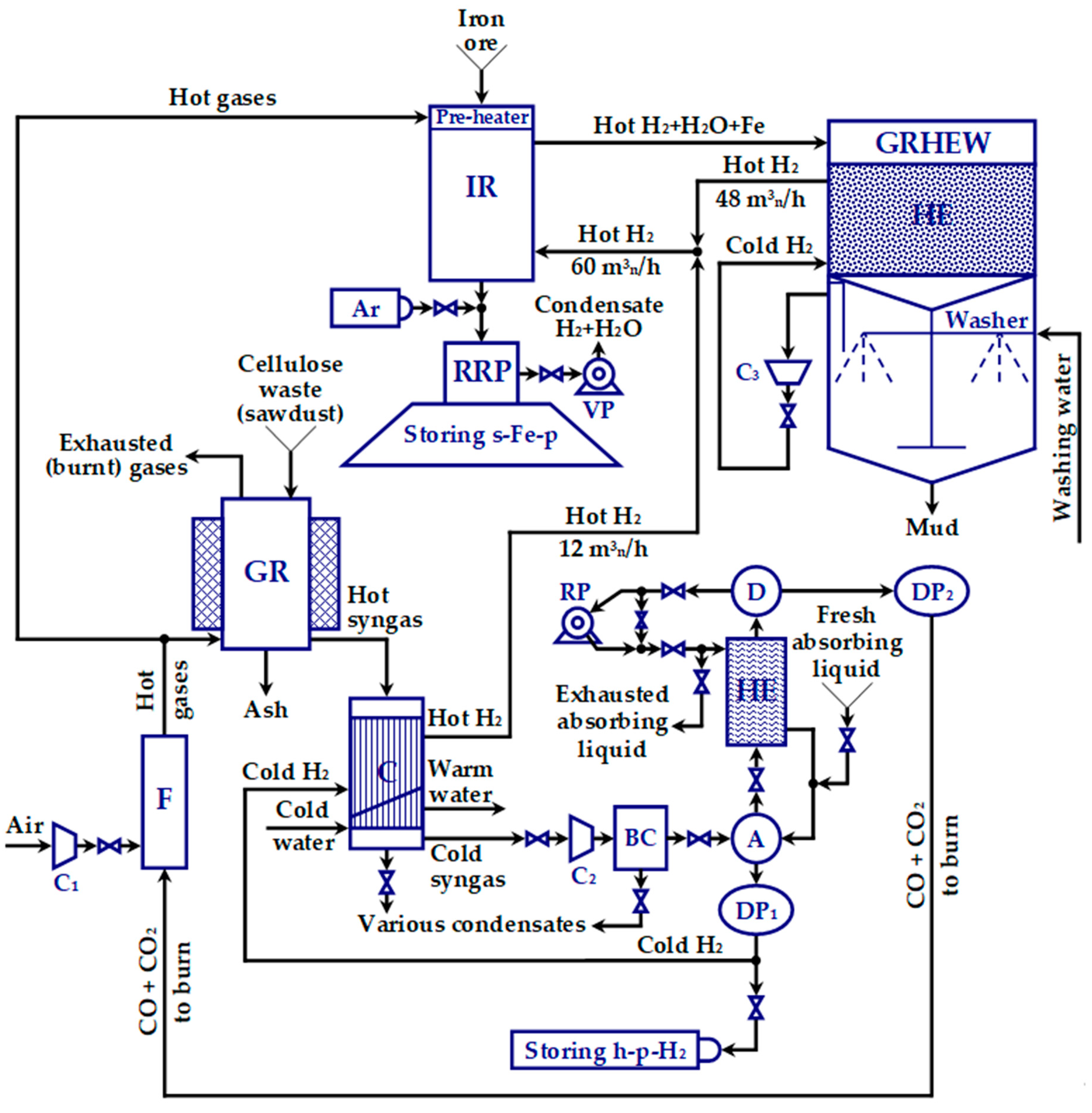
2.3.2. Designing the Gas Reactor (GR)
One aims to obtain 20 kg/h s-Fe-p (for which a flow of 0.6 m3n H2/kg Fe is required) and at least 12 m3n/h H2. To reach for this goal, it is necessary that HYRON installation produces a higher flow of hydrogen, e.g., in amount of 15 m3n/h H2 (including the hydrogen coming along with CO2 and CO).
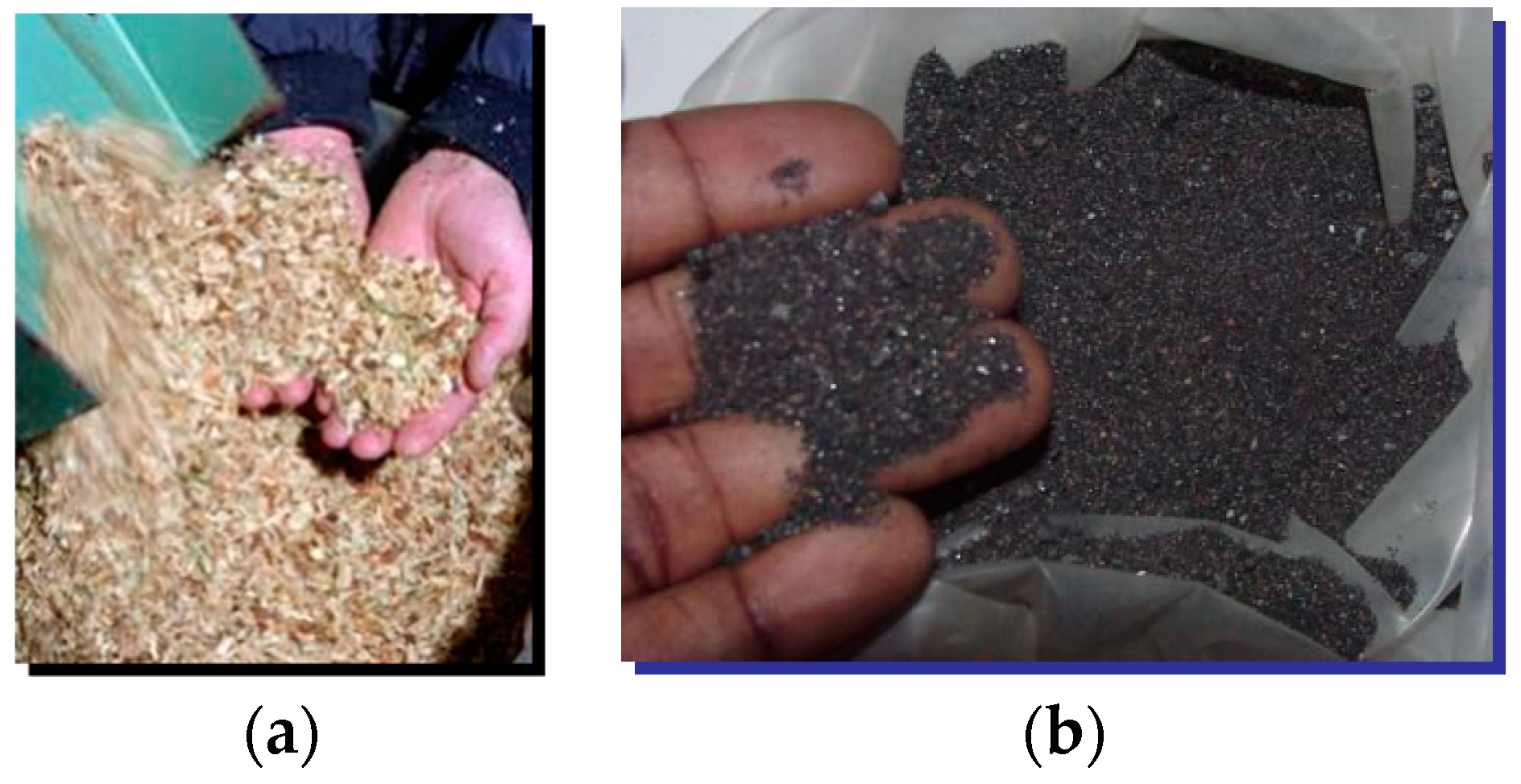
The chosen raw material is a ligno-cellulosic waste type of biomass (preferably sawdust), since it recycles CO2 in the natural photosynthesis process, is abundant, inexpensive, clean and it has a hydrogen content superior to other solid fuels. The mass composition of this biomass is similar to that of hardwood or resinous and straws. More specifically, a rudimentary proximate analysis led to the following composition of acquired sawdust: 50.8% carbon, 6.2% hydrogen and 43% oxygen. The participation of nitrogen (0.6%) was neglected and a minimum absolute humidity of 3% was considered. It follows that 1 kg of dried cellulosic waste (e.g., dsd) contains 42.3 mol carbon, 31 mol hydrogen and 13.4 mol oxygen.
As reported into the literature [
45,
46,
47,
48], at a temperature of 1000 °C, when biomass gasification occurs (according to reaction (1)), the syngas has the volumetric concentrations of 48% CO (41 mol CO), 1.5% CO
2 (1.3 mol CO
2), while 42.3 mol C are fully included into CO and CO
2. The carbon oxidation requires 21.8 mol O
2, but the biomass contains only 13.4 mol O
2. Thus, the remaining 8.4 mol are obtained from 16.8 mol H
2O. Consequently, the gasification reaction, in mol, is:
Since only a part of water vapor participates to the useful oxygen release, a water supplement is necessary, in order to keep the reaction alive. By only adding 3 mol of water to both terms of Equation (7), one obtains:
while the overall balance of water concentration is preserved.
For the useful water consumption (avoiding the steam production), the moisture of gasified sawdust has to be of 0.35 kg water within each kg of wsd, which means about 0.26 kg water within each kg of dsd. Hence, 1 kg dsd = 0.26/0.35 kg wsd ≅ 0.7429 kg wsd. The gasification of dsd, by using Equation (8), produces 1.07 m3n H2 / kg wsd ≅ 0.7949 m3n H2 / kg dsd.
In the first term of Equation (7), direct measurements have shown that the heat intake is limited to 4800 kcal/kg wsd. In the second term, the heat is converted from H2 and CO energy to the amount of approximately 4474 kcal/kg wsd. Nevertheless, gasification will only occur if the total heat intake equals the total transferred heat. Therefore, the difference of 326 kcal/kg wsd has to be supplied by the furnace. Obviously, the furnace has to ensure the necessary energy to produce at least 12 m3n/h H2 to send to the IR. To increase the purity of hydrogen employed to produce s-Fe-p, 13.4 m3n/h H2 has to be generated, the supplement of 1.4 m3n/h H2 being estimated as sufficient for a higher purification. The caloric efficiency of GR can easily be estimated, as this block is partly self-sustainable: it produces 4474 kcal/kg wsd and requires 4800 kcal/kg wsd, i.e., with 326/4474% ≅ 7% more. The GR efficiency is thus of about 93%, theoretically. Practically, after building the GR, its efficiency has been estimated to about 90%.
All the heat is required for cellulosic waste drying, vaporisation and overheating of supplementary water, pyrolysis and full gasification, increasing the reactants temperature up to 1000 °C, various dissipations (estimated at 75 kcal/kg wsd), as well as for the transfer outside the installation. Drying the cellulosic waste at about 100 °C consumes 281 kcal/kg wsd, and heating up to 450 °C, in order to complete the pyrolysis, consumes 273 kcal/kg wsd.
The heat consumption of pyrolysis and gasification is included in the isothermal balance of the two sides in Equation (8). The heating at 1000 °C of syngas resulted during the wsd evolution consumes about the same heat it gives during the cooling at 450 °C. The cooling between 450 °C and 100 °C is practically achieved by contributing to the reheating of the nearly dried syngas from about 20 °C to almost 950 °C (the water being drained in the liquid phase).
One can set as target a flow of 15 m
3n/h H
2 to be generated by the GR. This involves a consumption of approximately 14 kg/h dsd (with 26% humidity) or, equivalently, of about 19 kg/h wsd (with 35% humidity). Moreover, the hydrogen sent to IR transfers a heat flow of about 3413 kcal/h. Then, the total energy the GR has to consume is:
In F enters a flow of 41 mol/h CO and 3 m
3n/h H
2, which carry 48,320 kcal/h. Since the GR consumes only 7977 kcal/h, during the experiments, one decided to evacuate in the atmosphere the supplement of:
after complete burning of CO (to avoid any risk).
As already mentioned in
Section 2.2.2, the intensification of the heat exchange in the GR was achieved by radial blades placed on the inner mobile cylinder. In order to design the GR, a tester with electric heating for the two cylinders was first built. The drive blades had initially a length of 20 mm. Later on, after several tests, the GR module with gas heating was built. In both cases, the value of the heat transfer coefficient reported on the cylinders was of 325 kcal/m
2/h/K. By increasing the blade length to 30 mm, this value jumped by over 40%, at 450 kcal/m
2/h/K. Additionally, the thermal conductivity of blades has been amplified, by making them of copper (they can also be made of aluminium or latten in this aim).
Since the heat transfer is simultaneously realized by conduction and convection, it is natural to analyze both phenomena, in order to obtain the right size of GR.
Considering the mobile cylinder speed of 0.2 m/s and a rib tilting of 6°, it results a theoretical radial moving speed of sawdust estimated at 0,1xtg(6°)
≅ 0.02 m/s. The ribs take over the hot sawdust and move it to the central zone, stirring it continuously and recirculating it between the central cold zone and the hot lateral zone. If the real moving speed would be only 20% of the theoretical one, i.e., 0.004 m/s, since the density of the sawdust is of 200 kg/m
3, the specific flow of sawdust moved from the outer heater fixed cylinder to the inner colder mobile cylinder can be calculated as follows:
In Equation (11), the factor 0.5 is required by the existing of the sawdust reverse flow, from the cold cylinder to the hot cylinder.
Considering the specific heat of the sawdust of 0.6 kcal/kg/K and aiming that the warm wall transfers heat with a specific flow over 5000 kcal/m2/h, it results that the difference between the temperature of the sawdust near the lateral wall and the temperature of the central mixture is ΔT = 5000/1440/0.6 K ≅ 5.8 K. The conductive intake is estimated at about 20% of the moving sawdust intake, so that ΔT is reduced to 0.2 × 5.8 K ≅ 1.2 K. It results a specific heat flow transferred by conduction of 1440 × 0.6 × 1.2 kcal/m2/h ≅ 1037 kcal/m2/h, which means a specific heat transfer coefficient of 1037 kcal/m2/h/K.
Since the heater agent consists of the combustion gases, which produce low intensity convection under normal conditions, with a heat transfer coefficient of no more than 20 kcal/m2/h/K, it is also necessary to intensify this heat exchange. In the areas with temperatures below 400 °C, where the intensity of thermal radiation is relatively small, an intensification method could be the following: the gases will pass through a space between two parallel metallic plates, interconnected by thin copper wires (with maximum 1.5 mm in diameter and about 5 mm step) and blackened by pre-oxidation. The wires receive the heat with a heat transfer coefficient of approximately 100 kcal/m2/h/K, even at moderate speeds. They can send the heat by conduction to the walls that separate the gas channels, of 15 mm wide each. This increases the convective heat transfer coefficient to the value of 150 kcal/m2/h/K.
With this solution of convection heat transfer intensifying, an average heat transfer coefficient can be estimated, as follows:
Then, according to Equation (12), the average temperature offset is: ΔTmed = 5000/131 K ≅ 38 K.
The surface of the heater cylinder is estimated to the value of 7949/5000 m
2 ≅ 1.6 m
2. By taking into account the average temperature offset ΔT
med, one can choose a distance of 0.04 m between the two metallic cylinders of GR. Correspondingly, the mobile inner cylinder could have the diameter D
m = 0.3 m and the wall thickness of 0.003 m. Then the inside diameter of the fixed outer cylinder is D
f = D
m + 2 × (0.04 + 0.003) mm = 0.386 m. To increase the mechanical stiffness of the two cylinders, each one of them has been welded to a second coaxial cylinder. The mobile cylinder match has a smaller diameter, of 0.264 m, while the fixed cylinder match has a larger diameter, of 0.422 m. Thus, the two cylinders are welded at a distance of 0.018 mm from each other, in both cases. To estimate the height h of the cylinders, the Equation below can be used:
as the thermal transfer surface belongs to the fixed cylinder. From Equation (13), one obtains h
≅ 0.66 m. For safety reasons, the height was chosen to h = 0.85 m. All the cylinders were built from refractory steel pipes, with close sizes to the designed ones.
The combustion gases circulate through GR at a speed of about 0.21 m/s. In the hot part (at approximately 1000 °C), they enter with 1 m/s speed and in the cold part (at 80 °C), the burnt gases are evacuated at 0.28 m/s speed. The GR is thermally insulated, according to the temperatures of the outside cage (between 100 °C on top and 1000 °C at bottom). A ceramic coating is used to protect GR materials from thermal expansion during high operating temperature and ensures the insulation. Its thickness varies between 0.05 m on top and 0.12 m at bottom. The outer diameters of GR are approximately of 0.49 mm on top and of 0.63 m at bottom.
2.3.3. Designing the Cooler (C)
As already mentioned in
Section 2.2.2, in normal functioning regime, the RG produces a hot syngas consisting of H
2, CO, H
2O
vapor and small amount of CO
2. The hydrogen separation requires preliminary cooling of syngas, from approximately 1000 °C to 20 °C. As a compact and economical solution, the C was built from 1.5 mm thick plate iron (refractory in the hot zone), with rectangular channels of only 1.5 mm in width, in order to increase convection. The heat transferred by the cooled syngas (from about 1000 °C to 20 °C) is almost completely recovered by reheating the freshly separated h-p-H
2.
In the sequel, the C sizing and the estimation of the heat transfer surface are presented, based on the heat capacities of gases. The average temperature of syngas is (1000 + 20)/2 °C = 510 °C = 783 K. Consequently, the specific volumetric heat capacities of every gas in the mixture are easily specified from tables: kcal/m3/K, kcal/m3/K, kcal/m3/K, kcal/m3/K (both under and over 100 °C).
The average specific heat capacity of the gaseous mixture is derived from Dulong-Petit Law:
where
is the specific volumetric heat capacity of the chemical
and
is its mass ratio. The mass ration of each syngas compound has been estimated in
Section 2.2.3. Thus, the Equation (14) leads to the average syngas heat capacity:
44.1% CO; 2.1% CO
2; 2.5% H
2O
vaporThe syngas total flow
m
3/h, the water vaporization rate is
kg/h and the water vaporization heat capacity is
kcal/kg. Based on these specifications, it is possible to compute the heat flow transferred by the syngas as below:
where the difference of the two temperatures is
, and
. It results
kcal/h. This heat must be received by a flow of hydrogen with 95% purity at least, heated from 20 °C to 800 °C (hence, with a temperature difference of
). Given the hydrogen gaseous flow of about
m
3/h, the heat is received by hydrogen with the flow:
The hydrogen that C supplies is combined with the recirculated hydrogen provided by GRHEW (at 50 °C), in order to obtain a hydrogen flow with a temperature around 670 °C, at IR input. The hourly heat difference,
kcal/h, is received by a water flow, with the temperatures:
(at input),
(at output). This leads to a water flow of:
kg/h, where
kcal/kg/K is the specific mass heat of water. In order to decrease the final temperature of cooling water, this flow can be increased to the value of
kg/h. The final temperature will be then:
which is a realistic value.
Constructively, a pipe-in-pipe type of C was selected. This means that the cooling agent flows inside the inner pipe, and the gases to be cooled flow inside the outer pipe, which surrounds the inner one. There are two cooling zones: one for hydrogen and another one for water. For both of them, the cooling pipes have to be sized appropriately.
For hydrogen, it is necessary to start from the following design data specific to the block A-HE-D: output flow from A of 14.7 m
3n/h; temperature of 20 °C; output pressure from A of 2 bar; input pressure in DP
1 of 1.2 bar; gaseous mixture speed of 8 m/s. It results that the exhausting pipe diameter of H
2 in DP
1 could be computed as follows:
The same diameter is chosen also for the inner pipes of H2 inside C. Likewise, in order not to complicate the construction of C, the water pipes can have the same diameter, . For all of these pipes, the thickness was set to 2 mm. The outer pipes could have the diameter: .
The length of a H
2 pipe,
, was estimated based on the value of heat transfer flow between gases leaving the GR and hydrogen (
kcal/h, Equation (17)). This flow is radially transmitted through the cylindrical wall of the pipe, being defined by:
where
is the total heat transfer coefficient,
is the average surface of heat transfer, estimated by means of the logarithmic mean radius of the pipe,
, and
is the average temperature difference. By definition,
, where
m is the inner radius, while
m is the outer radius of the pipe. Thus,
m (same as the arithmetic mean) and
[m
2]. Next, for syngas coming from GR at the temperature of 1000 °C = 1273 K, one can evaluate the output temperature at the output of C, after being cooled with the cold hydrogen coming from DP
1. Thus,
Similarly, the cold hydrogen entering C has a temperature of 20 °C = 293 K, and the hydrogen entering IR has the temperature of 800 °C = 1073 K. Hence,
To evaluate the transfer surface, firstly the constant
has to be derived, from the Equation below:
where
is a partial heat transfer constant,
m is the outer pipe diameter, and
W/m/K is the thermal conductivity of the pipe. In order to calculate the constant
, the Nusselt number (
) is used, which leads, on one hand, to:
. On the other hand, this criterion can be determined by using Donahue’s Equation:
where
is the Reynolds number,
is the Prandtl number,
and
are the dynamic viscosities of the fluid in the middle of the flow and at the wall, respectively. Usually, the last ratio in Equation (24) is approximately unit. In order to estimate the two dimensionless numbers (
and
), one has to know: the hydrogen flow speed through the pipes (
m/s), the cinematic viscosity of hydrogen
m
2/s and the hydrogen density
kg/m
3. Thus:
taking into account that, for hydrogen, the specific mass heat is:
According to Equations (24) and (25), the Nusselt number is:
. Consequently,
W/m
2/K and
W/m
2/K (see Equation (23) again). Finally, from Equation (20), one obtains the pipe length:
The above reasoning can be resumed for water as cooling agent, to compute the length of corresponding pipes. This time, the following water specifications have to be used:
kcal/h;
m (same as for hydrogen); syngas needs to be cooled from 220 °C = 493 K to 20 °C = 293 K; the water has the input temperature of 20 °C = 293 K and the output temperature of 28 °C = 301 K (according to Equation (18)); the flow speed through the pipes is
m/s; the specific mass heat is
J/kg/K; the cinematic viscosity (at the average temperature of 24 °C) is
m
2/s; the density is
kg/m
3. Having these data, it results
;
;
;
;
W/m
2/K;
W/m
2/K. Consequently, the water pipe length is:
Taking into account the obtained values, the pipe constructive lengths can be chosen as: and .
2.3.4. Designing the A-HE-D block
A. The absorber (A)
In order to verify the results of the previous subsection, the diameter of syngas feed pipe entering A can be evaluated. As already mentioned, the warm syngas exits C with the flow
m
3/h, while the pressure equals 1 bar (before entering the compressor C
2). By accounting the mass ratios of each compound gas, this flow can be expressed as follows:
After the compressor C
2, the flow of the gaseous mixture is calculated by applying Boyle-Mariotte Law: p.V = constant. Considering that the gases are almost ideal, it results that, at a pressure of 2 bar, the overal flow becomes
m
3n/h. If the optimum speed of the syngas is 8 m/s (as of hydrogen through C), the minimum diameter of the feeding pipe in A is derived:
For safety reasons, the diameter can be chosen as for C, i.e., . The same diameter is also chosen for the discharge pipe of the unabsorbed hydrogen in A, on the top. It will have a pressure of about 2 bar, a temperature of maximum 35 °C and will enter a depressurizer to bring it to the pressure of 1.1–1.2 bar. The depressing process is strongly endothermic, such that the hydrogen becomes highly dry and cold (at approximately 25 °C). If the depressurizer is vertically placed, any wet compounds of hydrogen will fall back into A.
Further, the absorption process is analyzed. From literature data [
45,
46,
47,
49,
50], it results that in order to absorb 16 mL of CO, 1 mL of absorbent liquid is required, under normal conditions. For simplicity, the same ratio is assigned to CO
2 gas. Thus, for a flow of about 12.7 m
3n/h CO + 0.6 m
3n/h CO
2 = 13.3 m
3n/h (CO + CO
2), it is necessary an absorbent fluid flow of about 0.83 m
3/h. To be sure, the absorbent liquid flow is set to 1 m
3/h. This liquid enters A at the pressure of 2 bar, by means of a pump, which leads to a flow of
m
3/h, by using the Boyle-Mariotte Law. For an optimum inlet speed of the liquid in A of
m/s, the diameter of the liquid inlet/outlet pipe is:
In order to use the same type of pipe to as many components of the HYRON installation, one chooses the same diameter as above, i.e., .
The efficiency of gas absorption can be improved by increasing the mass transfer surface of certain gases in a liquid, through fillers. Consider that we have a 1 m
3 room full of fillers. After several experiments with different types of filler, it has been found that an optimal absorption surface is obtained by using cylindrical grains of polyamide 66 with 43% glass fibers having the size
mm and density
kg/m
3. The measured mass of the grains in the room is
. It follows that the grains take the effective volume
m
3 (accordingly, the air volume of is
m
3). Since the surface of a grain is
mm
2 and its volume is
mm
3, the number of grains in the room is
. They provide the total absorption surface
m
2. In order to size the absorber, it is important to define a parameter called the nominal diameter of the filler. This is actually the diameter of a sphere of volume equal to
and can be calculated as:
To determine the apparent moving speed of gas bubbles (
) through the selected filler, some tests of air sparging in water were run, in a column with heights ranging from 5 to 50 cm. The apparent speed is estimated by dividing the sparged gas flow
to the surface
corresponding to the gas bubbles accumulated at the top of filler column. This surface is evaluated by considering that the gas bubbles are placed on a disk with a certain radius. The results of tests are synthesized in
Table 1.
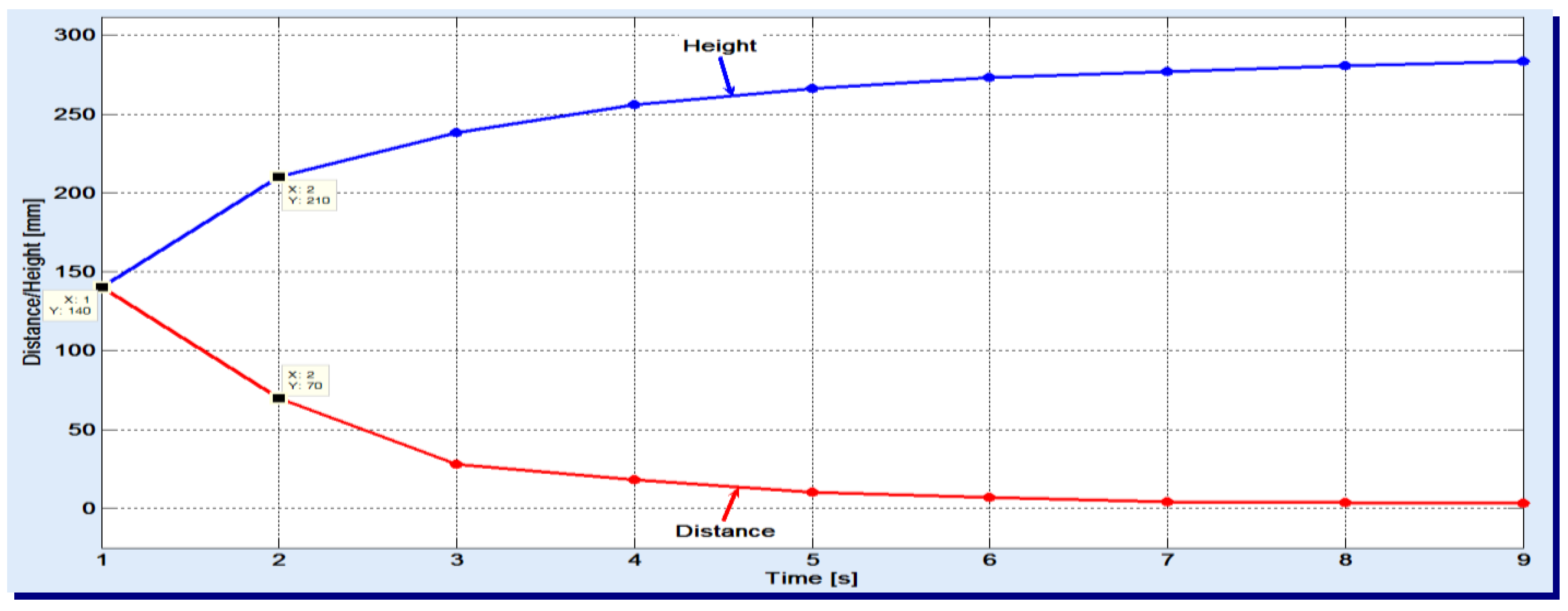
The used gas flow was set to the minimum necessary to stand against the hydrostatic pressure of column and complete the sparging. One noticed that the apparent speed slightly decreases with the increase of height. In the experiments, a 50 cm high filler column was used and the air was sparged. The results are displayed in
Figure 2.
Looking at the two variations, one can see, for example, that the gas bubbles have passed 140 mm in the first second and only 70 mm in the next second. As the duration increases, smaller and smaller distances are covered by the gas bubbles. These graphics also reveal that the entire filler column is basically divided into two zones:
the lower zone, of bubbles breaking, where absorption is less present; here, the syngas meet already saturated liquid with absorbed gases;
the upper zone, of effective absorption, with apparent speed of 3–5 mm/s.
In order to size the absorber, a known design method, which involves using the surface
, the diameter
(of Equation (32)), Semmelbauer Law and Delong-Petit Law was employed. The method is similar to the one described at length in [
51]. The volume of the filler column in the absorption process was estimated to at most 0.1 m
3 and, therefore, for the nominal diameter of absorber column equal to 0.5 m, the minimum height of this column is of 0.55 m (by accounting the two aforementioned zones). One can choose a lower rounded value for this height, since absorption occurs to some extent in the first zone as well. However, in order to increase the absorption target rate to 99%, to allow various approximations in the technological design and to prevent the possible malfunctions while operating the installation (such as excessive temperature rising, flooding of the absorbent liquid column, etc.) the A was considered to have cylindrical shape with total height
and diameter
.
The A compartments are as follows. The inferior zone I, at A bottom, has the height . In this zone, a pipes distribution system (with the same diameter of 0.03 m) is included. Each pipe has several holes of 3 mm, allowing the gas mixture to be sparged in the A, with a pressure of about 2 bar. The zone II, of the grains filler, has the height . The zone III, of feeding and liquid relaxation has the height . In this zone, the recirculated liquid feeding pipe is laterally connected (in the upper side). The zone IV, of hydrogen accumulation, has the height . The zone V, of drops deflector, on A top, has the height .
B. The Desorber (D)
The desorption process is completely reversible to absorption of gases into liquids. As in the case of absorption, both a very large surface of the liquid (to quickly release the absorbed gas) and a higher temperature (to help the desorption) are required. As already known, at 58 °C, the ammonium carbonate (NH4)2CO3 decomposes. Therefore, a saturated solution of CO and CO2 that enters the desorber at 68 °C was chosen. This temperature cannot be exceeded, otherwise the ammonium can be released, together with CO2.
The D block works under pressure (as A block does, as well). As already mentioned, the efficiency of the gas absorption process is estimated at 99%. The size computations are similar to those in the previous subsection. Thus, D results of cylindrical shape as well, with the height and the diameter .
The D compartments are as follows. In the zone I, on D top, of height , lies the drop deflector. This is identical to zone V of A. On the superior cover of D, an outlet flange to evacuate the gas mixture CO + CO2 is mounted. All the sizes are identical to those of A and with the same tightness requirements (especially as carbon monoxide (CO) is a toxic gas). Zone II, of saturated solution inlet, has the height . To simplify the construction of the modular assembly, one can use the same configuration of distribution pipes as in zone I of A. The spraying zone III has the height . In this area, finest sprays are obtained through nozzles. The filler column zone IV has the height and is similar to zone II of A. Here, the grain sizes can vary up to 4–6 mm. The zone V, where the recirculating liquid is collected, has the height . The flow of recirculating liquid equals the one of the absorbent solution (1 m3/h), at the temperature of 55–58°C.
C. The Heat Exchanger (HE)
The absorption process is carried out at a different temperature from the desorption one, so that A and D are connected to each other by means of an HE (see
Figure 1 again). Thus, the absorbent liquid (a copper-ammonium solution) enters HE, where is heated in the first stage from 35 °C to 65 °C and is cooled in the second stage from 55 °C to 25 °C. The heat power has the same value in both situations, and the heat capacity of recirculated liquid is the same as for the saturated liquid. The HE can be built following the classical pipe-mantle model. The heat transfer surface
(of HE), can be derived from the dynamic heat transfer Equation below:
where
(kg/s) is the mass flow,
(J/kg/K) is the heat capacity, both of the absorbent liquid,
[K] is the temperature difference,
(W/m
2/K) is the total heat transfer coefficient of HE and
(K) is the average temperature difference. One can easily note that the absolute temperature difference is the same in both stages, i.e., 30 K.
Given the following sizing values:
;
(estimated for the “through pipes–between pipes” type, with roughness
);
. The mass flow and the heat capacity of the absorbent liquid have to be determined. As recommended in [
45], the absorbent liquid (for CO and possibly CO
2) is an aqueous solution of ammonium, cuprous chloride and ammonium chloride. The absorbent solution is prepared after the following recipe, presented in
Table 2.
From the first column of the table, it follows straightforwardly:
. From the same table, an incremental-atomic type modeling can be performed to determine the heat capacity of the copper-ammonia solution. One applies Kopp-Neumann Law [
52], where the heat capacity of a chemical compound (CC) made of primary elements (PE) can be evaluated as follows:
where
is the mol number, and
is the heat capacity, both for
. By using the law (34), for the compounds in
Table 2, one obtains:
From the third coloumn of
Table 2, it also results the mass ratios of compounds:
By using the results from Equations (35) and (36) with Dulong-Petit Law (14), one obtains:
By inserting the result (37) in Equation (33), one obtains the heat transfer surface:
Constructively, HE is a vertical cylinder with the height
. This height is chosen so that the pipes that cross it longitudinally have the length of 1.2 m (
) too, as in the case of C block. Obviously, these pipes will have also the diameter 0.03 m (
). Then, in order to ensure the heat transfer surface (38), a minimum number of parallel pipes is required:
They can be distributed on a disc of the cylinder base with the diameter , leaving a distance of 0.012 m between them.
In order to compute the practical amount of copper-ammonium solution that resides in the A-HE-D block, it is necessary to know the volumes and spaces it floods. An acceptable approximation of this volume is obtained by only accounting the volumes of A, D and HE blocks. According to A and D sizes, the following volumes flood by the absorbent liquid are obtained:
;
(the height of 0.1 m added to the height of zone IV of D is an approximation of the partial flood volume in the other zones);
. From here, one obtains the total volume flood by the absorbent liquid:
. According to
Table 2, each compound fills a part of this volume, depending on the number of moles. When taking into account the density of each compound (also shown in
Table 2), one obtains the corresponding quantities to mix, in order to prepare the absorbent liquid to use (see the last column of
Table 2). Consequently, the overall quantity of absorbent liquid to prepare is of 815.49 kg. This recipe was selected so that the price is affordable (cuprous chloride being quite expensive).
The absorbent liquid in this recipe is obtained as follows: the water is mixed first with the two salts (CuCl and NH
4Cl), then the ammonium (NH
3) is added and, finally, the mix is blended until the solution becomes homogenous. The preparation is realized in a plastic made bowl of sufficient capacity. Due to its basic nature, the solution will be able to absorb CO
2 too, this being transformed into ammonium carbonate [(NH
4)
2CO
3] during the absorption process. The copper-ammonium solution has the property that 1 mL (of it) can absorb 16 mL CO. The desorption process may have lower efficiency than the absorption process. It is possible that the desorption process is less efficient than the absorption. The decomposition point of ammonium carbonate is at 58°C, which requires that the desorption process of CO and CO
2 occurs at 60–65 °C. Therefore, the copper-ammonium solution should be refreshed periodically with 5–10% (once every 24 h), in order not to affect the absorption power. More specifically, 5–10% of the total recirculated solution is exhausted by a purge placed at A-HE-D block bottom and an equal amount of fresh solution is added through the feeder placed on top, as
Figure 1 displays.
2.3.5. Designing the Iron Reactor (IR)
As previously mentioned, IR is aimed to produce sufficiently pure, decarburized s-Fe-p, by using shredded iron ore (e.g., hematite). An important goal in the design of HYRON installation was to ensure intensification of thermo-chemical processes, by uniformly distributing the reactants, mainly the ore, the hydrogen and the steam. The tasks to perform inside the IR are: realize relatively uniform temperature, inject a uniform hydrogen flow (of 0.6 m3n/kg Fe) to cross the ore layer, work with minimum ore thickness, ensure low speed of the overall flow, below the speed of particles greater than 40 μm in size (which stand for about 95% of the ore mass).
To fulfill those tasks, a supplementary source of heat, electrically supplied, is necessary. This heat comes in addition to the heat generated by hydrogen oxidation in contact with iron ore. After some experimental tests, it was estimated that, to form 1 kg Fe by removing the metal from Fe2O3, it is necessary a heat amount of 1763 kcal (≅7.38 MJ). Since H2 has a burning specific heat of 57,810 kcal/kmol, and the atomic mass of Fe is 55.845 kg/kmol, according to reaction (4) (where the stoichiometric coefficients of H2 and Fe are 3 and 2, respectively), the thermic deficit is: 1763 – 3 × 57,810/2/55.845 kcal/kg Fe ≅ –210 kcal/kg Fe. From the total amount of 1763 kcal/kg Fe, the quantity of 210 kcal/kg Fe represents about 12%. Therefore, to produce 20 kg s-Fe-p per hour, an amount of electrical energy of 20 × 210 kcal/h = 4200 kcal/h ≅ 4.885 kW is needed. By adding 2% for power dissipation, one has to employ a power source of 5 kW. The electrical energy is dissipated inside the IR by means of three rows of Kanthal strips, which were sized so that at a nominal voltage of 220 V, they provide 5 kW of power. Hence, the global resistance of electrical heater is 2202/5000 ≅ 9.7 Ω. In order to achieve this value, the strips have to be disposed in several parallel resistors. Thus, two groups of resistors were interconnected in parallel, one on each half of the IR horizontal section. Each group consists of three resistors, also connected in parallel. The required resistance of a group is of 2 × 9.7 = 19.4 Ω and each resistance (from a total of six for the whole reactor) is of 3 × 19.4 = 58.2 Ω. Starting from this value, the total length of the Kanthal row (for all six resistors) was estimated at 275 m. The Kanthal strip was disposed in 191 parallel strips, with vertical width and the distance between them of 2.3 mm.
As previously mentioned in
Section 3, the mixture of 81% H
2 and 19% H
2O
vapor is cooling in GRHEW, from 570 °C to approximately 15 °C. The condensation reduces the water ratio in the hydrogen flow with 2%. Hence, one obtains a ratio of 0.19/0.81 – 0.02 ≅ 0.215 m
3n H
2O
vapor / m
3n H
2. Since 1 m
3n of water vapor weights 0.79 kg, the water vapor participation is of 0.215 × 0.79 kg H
2O
vapor/m
3n H
2, meaning 0.17 kg H
2O
vapor / m
3n H
2. One aims the HYRON installation to generate 20 kg/h s-Fe-p. Coming back again to reaction (4), a flow of 20 × (3 × 18.015)/ (2 × 55.845) ≅ 9.68 kg/h H
2O
vapor is produced simultaneously. (Note that the atomic mass of water vapor is 18.015 kg/kmol.) Through the ore in process of deoxidation, a flow of 9.68/0.17 ≅ 56.94 m
3n/h H
2 together with an estimated water vapor flow of 0.215 × 56.94 m
3n/h H
2O
vapor ≅ 12.24 m
3n/h H
2O
vapor have to circulate. Thus, the mixture H
2 + H
2O
vapor passes through the ore, with the following output flow (at the temperature of 570 °C = 843 K):
Recall that, to convert 1 m3n of gas in absolute m3, the gases law has to be employed: p.V/T = constant. Since the standard temperature of 1 m3n is of 0 °C = 273 K, if the pressure is constant, the new volume depends on the ratio between the effective temperature (e.g., 843 K) and the standard temperature (273 K).
To allow completion of reduction reaction, it is necessary that the ore particles with sizes of at least 40 μm do not be captured by the exhausted gas from IR. Therefore, the flow section of the gas mixture was sized to the value 0.5 × 0.5 = 0.25 m2, which, according to Equation (40), leads to a flow speed of 0.06/0.25 m/s = 0.24 m/s.
To estimate the iron ore flow that feeds IR (with no more than 200 μm in particles size), it is necessary to return to the reaction (4), where one notes that 2 mol of Fe are obtained from 1 mol Fe
2O
3 (ore). Since the atomic mass of oxygen is about 16 kg/kmol, it follows that the atomic mass of ore is (2 × 55.845 + 3 × 16) kg/kmol ≅ 159.688 kg/kmol. Then, to obtain a flow of 20 kg/h s-Fe-p, a necessary iron ore flow is estimated at:
Thus, the IR can be fed with an iron ore flow of 29 kg/h. The IR bunker storage volume is of about 45 l, with a height of 0.25 m, and has to be supplied every 4 h with iron ore. It is suitable that the bunker includes the ore heater, which consists of 12 box type pieces, each one with the sizes of 0.5 × 0.15 × 0.15 [m]. This means the actual height of bunker+heater is 0.25 + 0.15 = 0.4 m. Such a box has an inlet connection for the combustion gases to come, of internal diameter of over 10 mm (at bottom) and an outlet connection to evacuate resulted gases (on top). The input temperature of the combustion gases is of 650 °C. They heat the boxes in contact with the iron ore and are evacuated at about 60 °C. Thus, the ore is heated from 20 °C to 580 °C. To keep the construction as simple as possible, the boxes were so designed that the hot gases circulate through channels of 4.5 × 11 (mm) in section, created along the 0.5 m length of the boxes and connected in cascade.
Finally, all IR components (some of them are less important and not described in the paper), lead to an aggregate that could fit into a virtual cylinder with the diameter of 1.6 m and the height of 2.2 m (including the metallic support of 1.2 m height).
2.3.6. Designing the GRHEW Block
The GRHEW main purpose is to perform cooling of the mix 81%H2 + 19%H2Ovapor (at 580 °C = 853 K) by means of cold H2. Thus, water condensation occurs, followed by evacuation. Subsequently, the possible existing residual iron in the mix has to be removed by the gases washer located at GRHEW bottom. In the previous subsection, one estimated that the iron ore requires a necessary deoxidation H2 flow of 56.94 m3n/h. Furthermore, it has been set that the gas exhausting speed (which does not cause capturing the particles with more than 40 μm in size) is of 0.24 m/s. These parameters lead to an estimated section of vertical ascending reducing gaseous mixture flow of 56.94 × (853/273)/(3600 × 0.24) m2 ≅ 0.2059 m2. Thus, one can chose a section of 0.5 × 0.5 m2 = 0.25 m2.
The whole construction of HE is metallic. From all acceptable constructive options, the parallel planar plate heater, with free distances of only 1.5 mm between plates, was chosen. Consider the laminar flow of the two thermic agents whose specific heat transfer coefficients are 225 kcal/m2/h/K (for H2) and 440 kcal/m2/h/K (for H2Ovapor). The overall specific heat transfer coefficient, , is then equal to 1/(1/225 + 1/440) kcal/m2/h/K ≅ 149 kcal/m2/h/K. Taking into account the thermal resistance of the metal plate, the coefficient decreases to .
As explained in
Section 2.2.6, the gaseous mixture coming from IR cools from 580 °C to 150 °C, while the cooling agent (H
2) warms from 20 °C to 570 °C. Consequently, the difference between the average temperatures of the thermal agents is:
Since the heat flow exchanged between agents is
(see
Section 2.2.6), it follows that the minimum surface required for this heat exchange is:
Considering the heat losses within HE, one can choose . The channels between the plates were sized to 150 × 500 [mm]. Given , the necessary minimum number of such channels is then: 1.4/(0.15 × 0.5) ≅ 19, which means 20 plates. The plate thickness being of 1 mm (with 1.5 mm between plates), it results that the total width of the metallic case incorporating the HE is: (20 × 1 + 19 × 1.5) mm = 48.5 mm (as the lateral plates are in contact with the case). Hence, the HE is a metallic parallelepiped with sizes: 150 × 48.5 × 500 (mm). It is covered with a cylindrical insulating coating (through which various input/output heat agent pipes pass), of 0.46 m in diameter and 1 m high.
For the gas washer, similar computations are developed, based on the thermodynamic analysis of water vapor condensation, cooling water heating (from 20 °C to 45 °C) through the contact with pre-cooled gases (at 150 °C) and the effective cooling of hydrogen. Thus, it resulted that the washer has a cylindrical shape with an inferior conic cap, having an inner diameter of 0.32 m and a height of 0.65 m. It is connected with the HE by means of an adjustment flange. Overall, the GRHEW has a height of about 1.65 m.


