Designing the Composition of Cement Stabilized Rammed Earth Using Artificial Neural Networks


Abstract
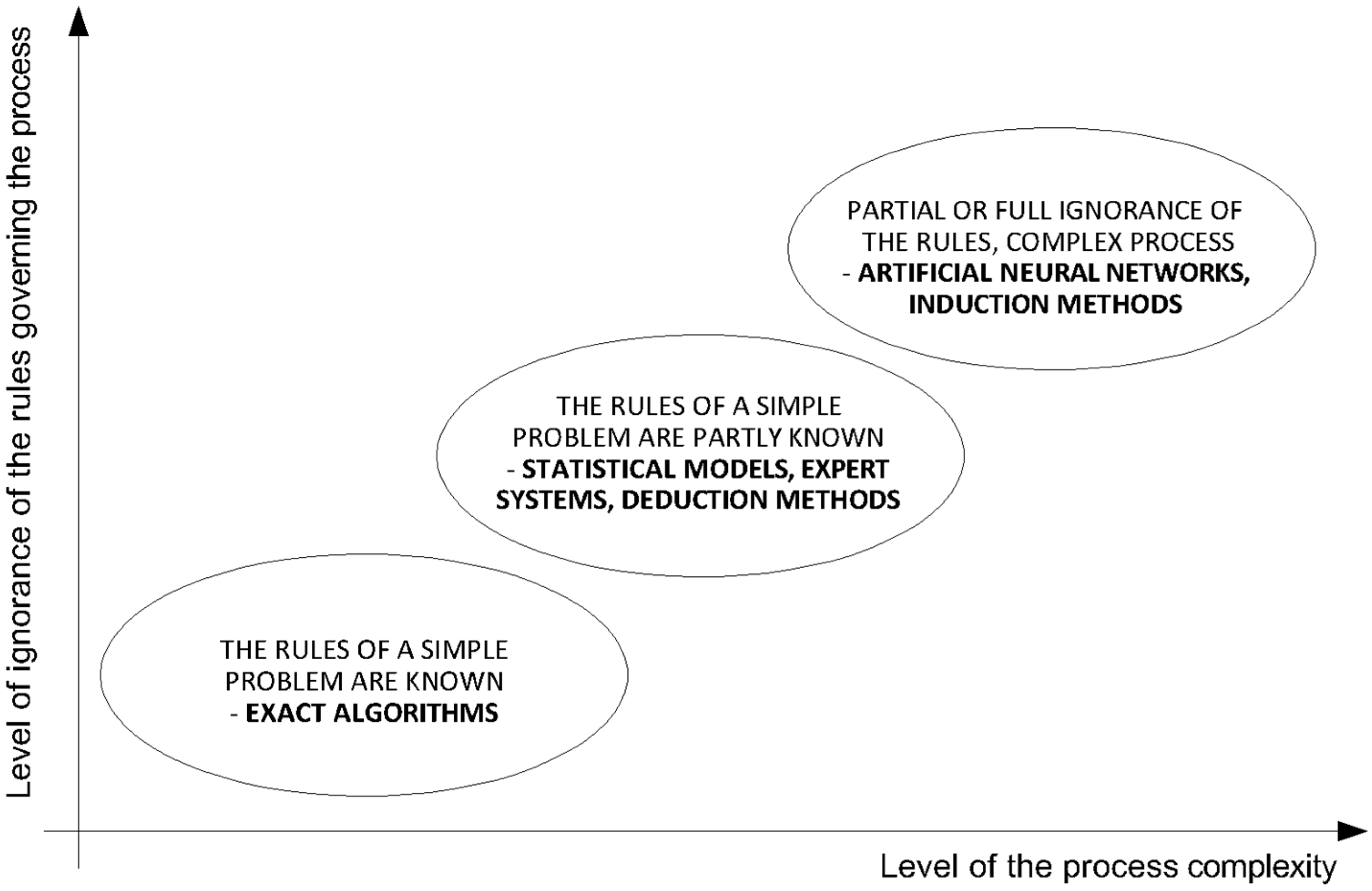
1. Introduction
- -
- Techniques that use earth in load-bearing monolithic constructions.
- -
- Techniques that use earth in load-bearing masonry structures.
- -
- Techniques that use earth as a non-bearing construction material in combination with a supporting structure of another material.
- -
- Shapes of the tested samples,
- -
- Energy used in ramming samples and the related volume density of samples,
- -
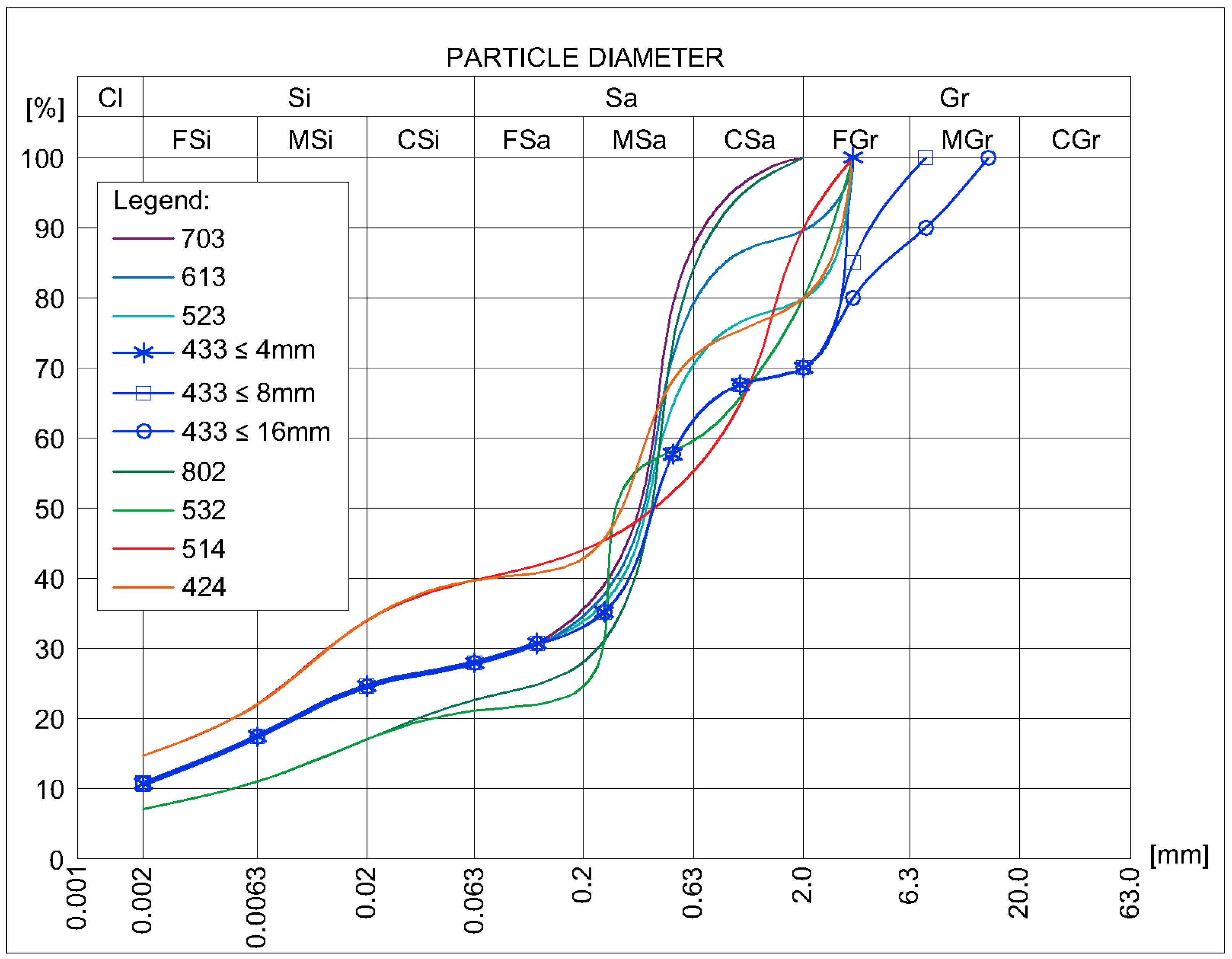
- Particle size distribution of the earth used in the mixture,
- -
- Mineral and chemical composition of the earth,
- -
- Moisture content of the earth mixture,
- -
- Moisture content of the samples at the time of the test,
- -
- Content and type of Portland cement,
- -
- Duration and conditions of samples storage before strength tests.
2. Materials and Methods
2.1. Database of CSRE Test Results
2.1.1. Materials
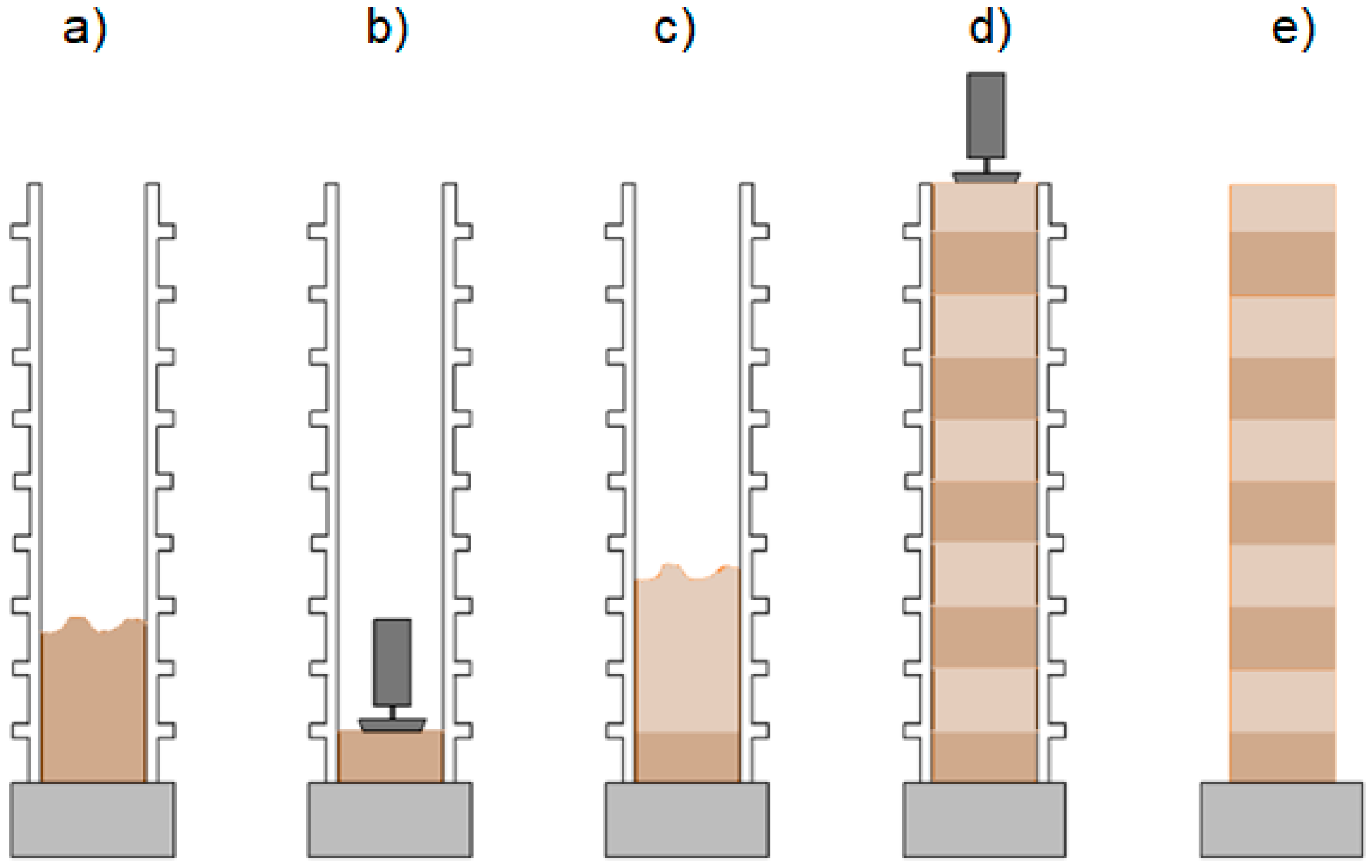
2.1.2. Preparation of Samples
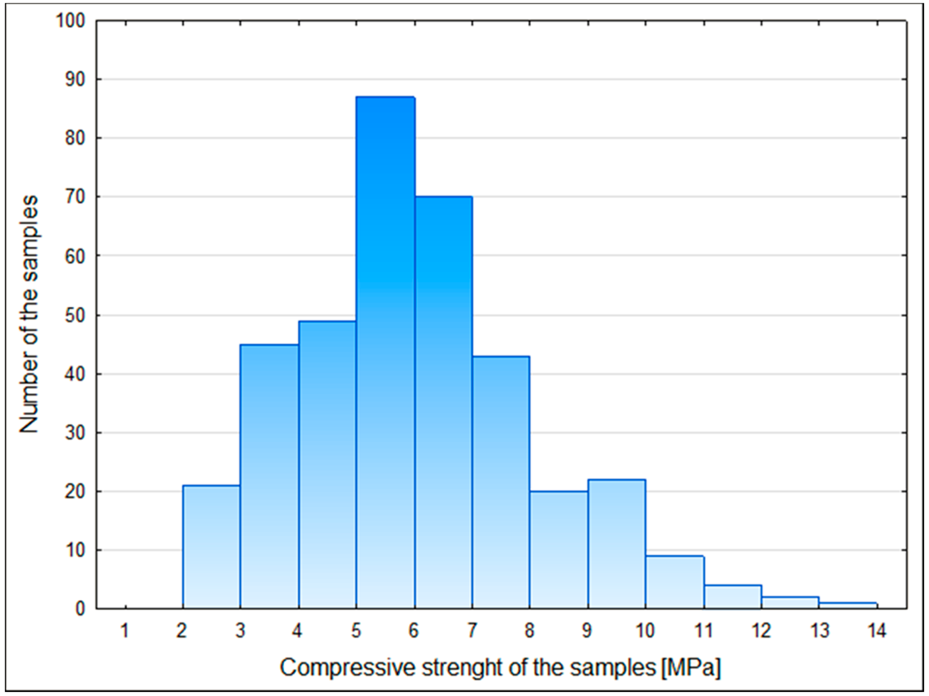
2.1.3. Results of Testing the Samples
2.2. Proposed Solution
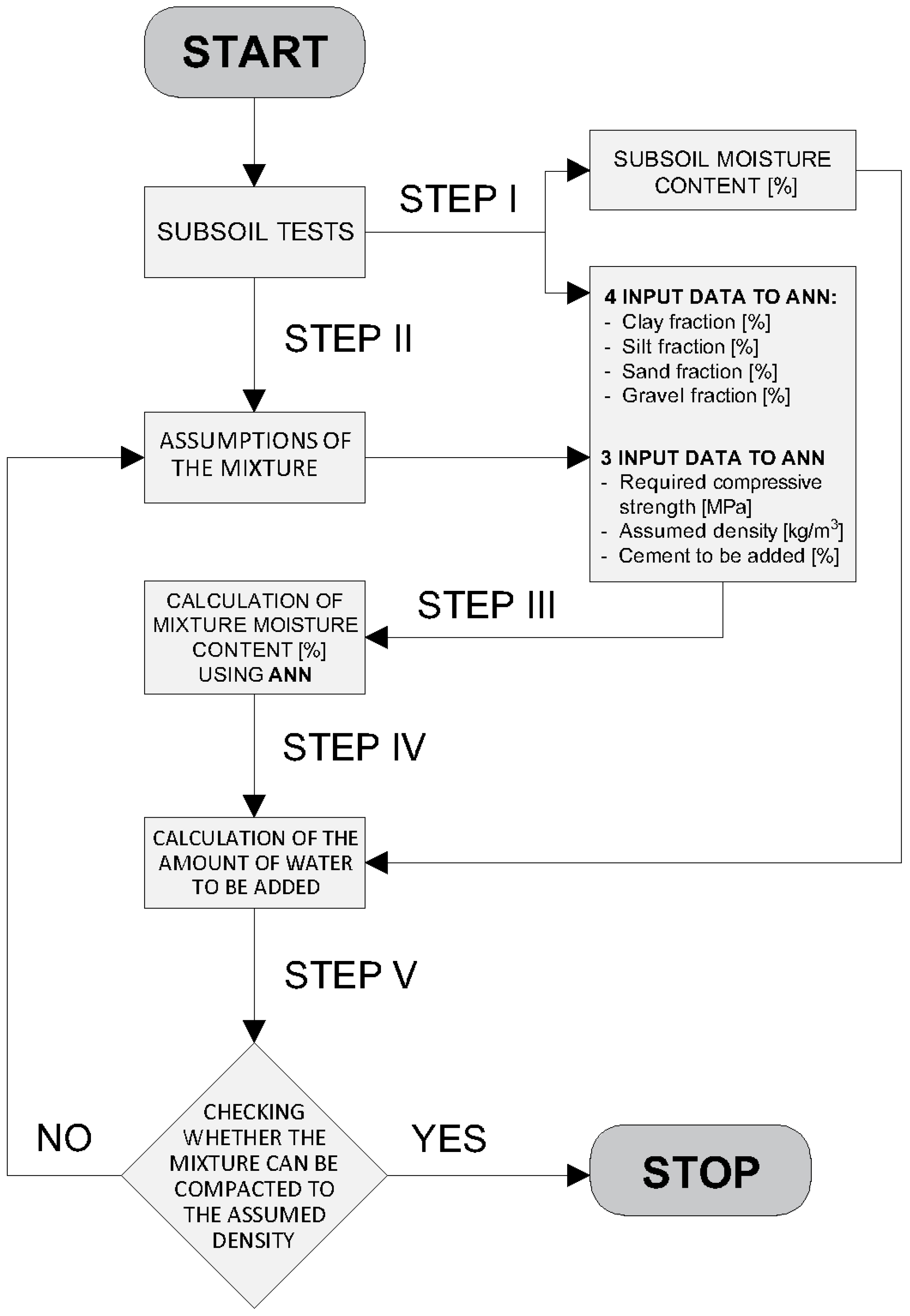
2.2.1. Algorithm
- -
- The amount of Portland cement to be added,
- -
- The amount of water,
- -
- The ramming energy needed to obtain a specific dry density of the compacted soil mixture.
- -
- The amount of cement to be added,
- -
- The density of compacted sample,
- -
- The compressive strength.
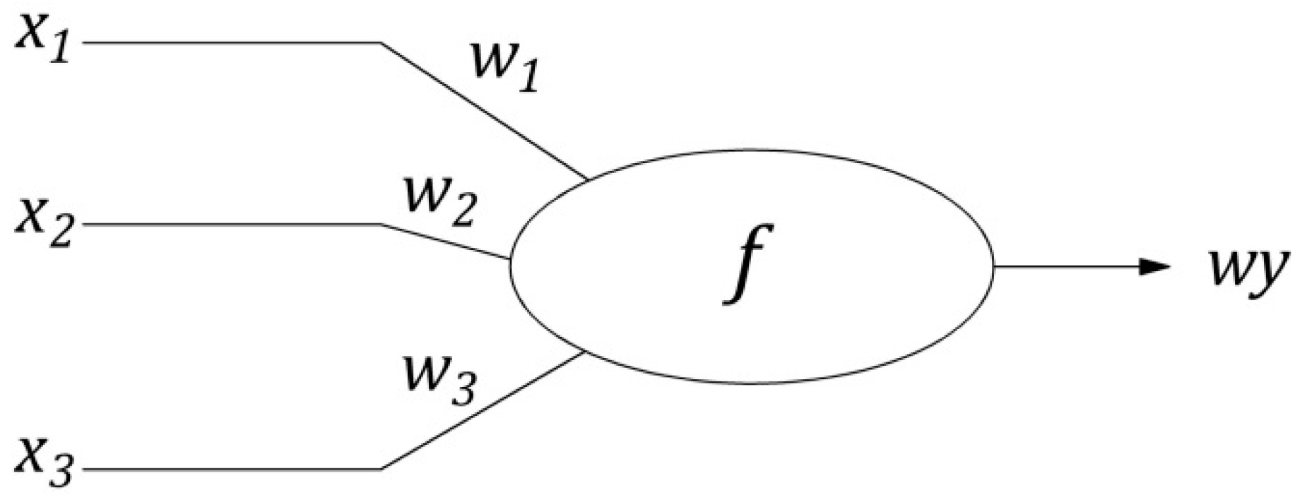
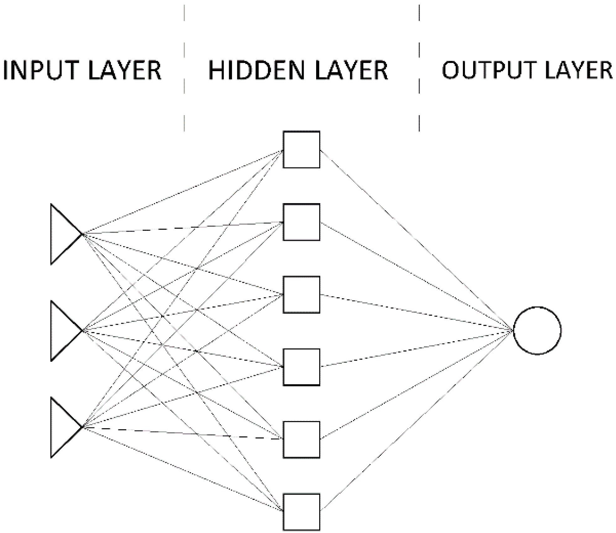
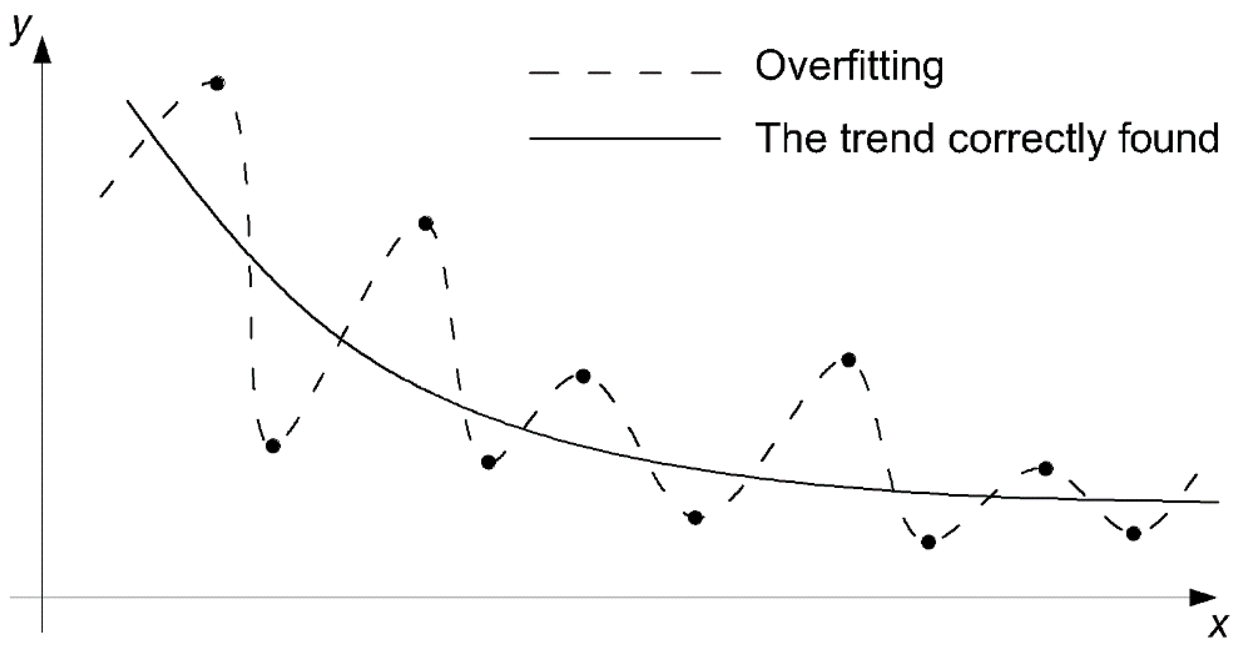
2.2.2. Creating the Artificial Neural Networks
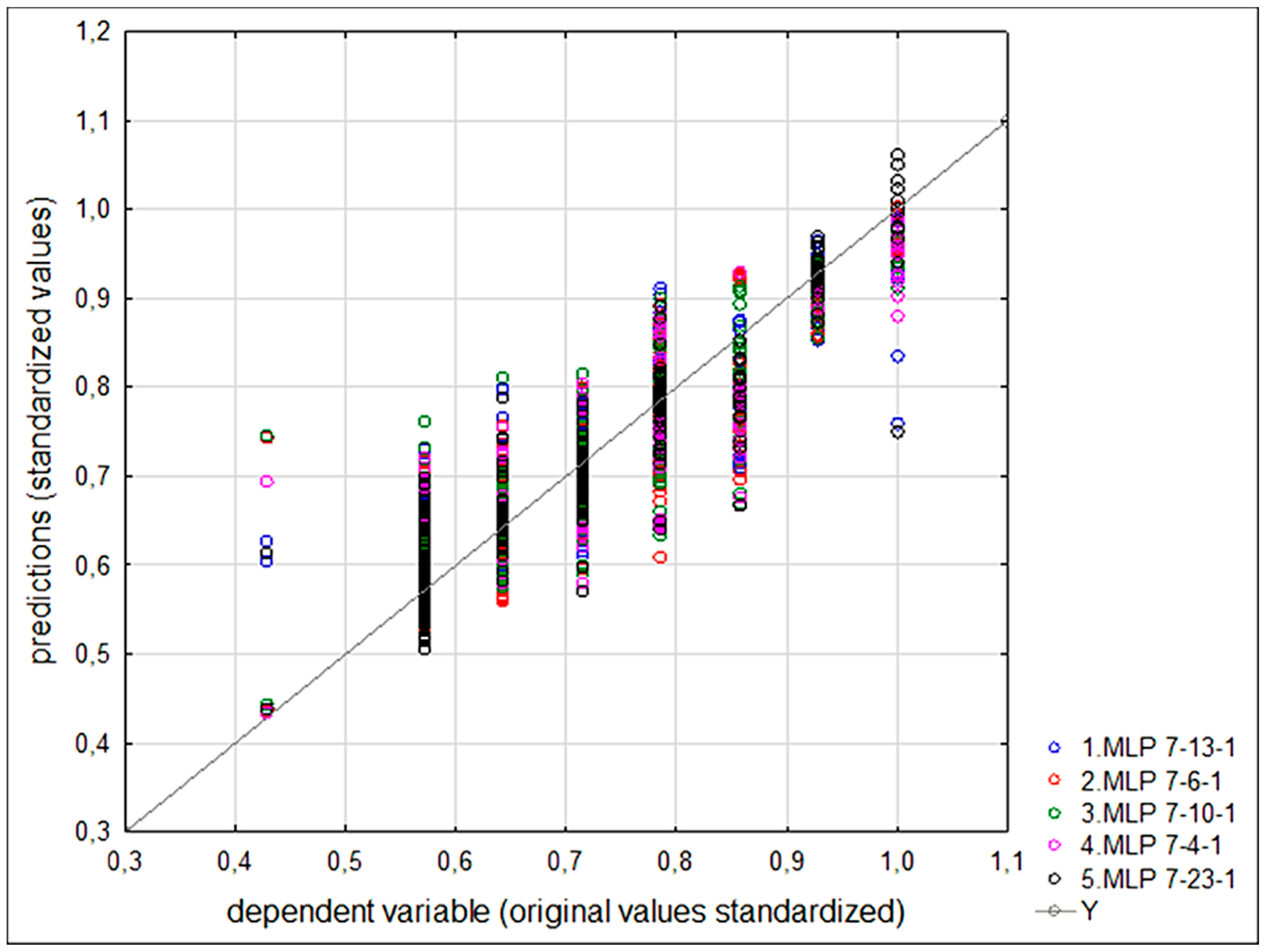
3. Results
- -
- Mean absolute error (MAE)
- -
- Mean absolute percentage error (MAPE)
- -
- Maximum absolute percentage error (maxAPE)
4. Discussion
5. Conclusions
Author Contributions
Funding
Acknowledgments
Conflicts of Interest
Appendix A

| No. | Particle size Distribution [%] | Cement Addition [%] | Moisture Content [%] | Density [kg/m3] | Compressive Strength [MPa] | |||
|---|---|---|---|---|---|---|---|---|
| Clay | Silt | Sand | Gravel | |||||
| 1 | 0.105 | 0.192 | 0.403 | 0.300 | 3.0 | 9.0 | 2296.29 | 4.1791 |
| 2 | 0.105 | 0.192 | 0.403 | 0.300 | 3.0 | 9.0 | 2300.48 | 3.5000 |
| 3 | 0.105 | 0.192 | 0.403 | 0.300 | 3.0 | 9.0 | 2277.39 | 3.2511 |
| 4 | 0.105 | 0.192 | 0.403 | 0.300 | 3.0 | 9.0 | 2270.35 | 3.1841 |
| 5 | 0.105 | 0.192 | 0.403 | 0.300 | 3.0 | 9.0 | 2309.10 | 4.1584 |
| 6 | 0.105 | 0.192 | 0.403 | 0.300 | 3.0 | 9.0 | 2295.20 | 4.0098 |
| 7 | 0.105 | 0.192 | 0.403 | 0.300 | 3.0 | 9.0 | 2311.22 | 4.2000 |
| 8 | 0.105 | 0.192 | 0.403 | 0.300 | 3.0 | 9.0 | 2277.22 | 3.5821 |
| 9 | 0.105 | 0.192 | 0.403 | 0.300 | 3.0 | 9.0 | 2295.75 | 3.1841 |
| 10 | 0.105 | 0.201 | 0.494 | 0.200 | 3.0 | 9.0 | 2252.05 | 2.5742 |
| 11 | 0.105 | 0.201 | 0.494 | 0.200 | 3.0 | 9.0 | 2273.63 | 2.5373 |
| 12 | 0.105 | 0.201 | 0.494 | 0.200 | 3.0 | 9.0 | 2168.93 | 2.6500 |
| 13 | 0.105 | 0.201 | 0.494 | 0.200 | 3.0 | 9.0 | 2284.03 | 2.8570 |
| 14 | 0.105 | 0.201 | 0.494 | 0.200 | 3.0 | 9.0 | 2260.27 | 2.7861 |
| 15 | 0.105 | 0.201 | 0.494 | 0.200 | 3.0 | 9.0 | 2275.85 | 2.8570 |
| 16 | 0.105 | 0.201 | 0.494 | 0.200 | 3.0 | 9.0 | 2280.89 | 2.7227 |
| 17 | 0.105 | 0.201 | 0.494 | 0.200 | 3.0 | 9.0 | 2282.96 | 2.7363 |
| 18 | 0.105 | 0.201 | 0.494 | 0.200 | 3.0 | 9.0 | 2258.95 | 2.4378 |
| 19 | 0.105 | 0.201 | 0.494 | 0.200 | 3.0 | 9.0 | 2267.48 | 2.4998 |
| 20 | 0.105 | 0.210 | 0.585 | 0.100 | 3.0 | 9.0 | 2252.37 | 3.2338 |
| 21 | 0.105 | 0.210 | 0.585 | 0.100 | 3.0 | 9.0 | 2246.32 | 3.0846 |
| 22 | 0.105 | 0.210 | 0.585 | 0.100 | 3.0 | 9.0 | 2221.56 | 3.4314 |
| 23 | 0.105 | 0.210 | 0.585 | 0.100 | 3.0 | 9.0 | 2248.51 | 2.9208 |
| 24 | 0.105 | 0.210 | 0.585 | 0.100 | 3.0 | 9.0 | 2267.34 | 3.1500 |
| 25 | 0.105 | 0.210 | 0.585 | 0.100 | 3.0 | 9.0 | 2288.72 | 3.3500 |
| 26 | 0.105 | 0.210 | 0.585 | 0.100 | 3.0 | 9.0 | 2275.49 | 3.3000 |
| 27 | 0.105 | 0.210 | 0.585 | 0.100 | 3.0 | 9.0 | 2251.15 | 3.3333 |
| 28 | 0.105 | 0.210 | 0.585 | 0.100 | 3.0 | 9.0 | 2250.36 | 3.1683 |
| 29 | 0.105 | 0.219 | 0.676 | 0.000 | 3.0 | 10.0 | 2232.84 | 3.3333 |
| 30 | 0.105 | 0.219 | 0.676 | 0.000 | 3.0 | 10.0 | 2212.64 | 3.3663 |
| 31 | 0.105 | 0.219 | 0.676 | 0.000 | 3.0 | 10.0 | 2238.93 | 3.3333 |
| 32 | 0.105 | 0.219 | 0.676 | 0.000 | 3.0 | 10.0 | 2252.73 | 3.2672 |
| 33 | 0.105 | 0.219 | 0.676 | 0.000 | 3.0 | 10.0 | 2250.86 | 3.4171 |
| 34 | 0.105 | 0.219 | 0.676 | 0.000 | 3.0 | 10.0 | 2237.22 | 3.4826 |
| 35 | 0.105 | 0.219 | 0.676 | 0.000 | 3.0 | 10.0 | 2254.71 | 3.4328 |
| 36 | 0.105 | 0.219 | 0.676 | 0.000 | 3.0 | 10.0 | 2225.45 | 3.2177 |
| 37 | 0.140 | 0.253 | 0.507 | 0.100 | 6.0 | 11.0 | 2271.13 | 5.4000 |
| 38 | 0.140 | 0.253 | 0.507 | 0.100 | 6.0 | 11.0 | 2294.90 | 5.3000 |
| 39 | 0.140 | 0.253 | 0.507 | 0.100 | 6.0 | 11.0 | 2306.25 | 5.4500 |
| 40 | 0.140 | 0.253 | 0.507 | 0.100 | 6.0 | 11.0 | 2313.54 | 5.1500 |
| 41 | 0.140 | 0.253 | 0.507 | 0.100 | 6.0 | 11.0 | 2317.35 | 4.6500 |
| 42 | 0.140 | 0.253 | 0.507 | 0.100 | 6.0 | 11.0 | 2293.48 | 4.8000 |
| 43 | 0.140 | 0.244 | 0.416 | 0.200 | 6.0 | 11.0 | 2285.29 | 6.6000 |
| 44 | 0.140 | 0.244 | 0.416 | 0.200 | 6.0 | 11.0 | 2303.33 | 6.1000 |
| 45 | 0.140 | 0.244 | 0.416 | 0.200 | 6.0 | 11.0 | 2393.55 | 6.8000 |
| 46 | 0.140 | 0.244 | 0.416 | 0.200 | 6.0 | 11.0 | 2283.51 | 6.9000 |
| 47 | 0.140 | 0.244 | 0.416 | 0.200 | 6.0 | 11.0 | 2314.29 | 6.9000 |
| 48 | 0.105 | 0.192 | 0.403 | 0.300 | 6.0 | 8.0 | 2258.96 | 7.1802 |
| 49 | 0.105 | 0.192 | 0.403 | 0.300 | 6.0 | 8.0 | 2235.14 | 7.4666 |
| 50 | 0.105 | 0.192 | 0.403 | 0.300 | 6.0 | 8.0 | 2271.98 | 7.1465 |
| 51 | 0.105 | 0.192 | 0.403 | 0.300 | 6.0 | 8.0 | 2263.90 | 5.9293 |
| 52 | 0.105 | 0.192 | 0.403 | 0.300 | 6.0 | 8.0 | 2292.21 | 8.0000 |
| 53 | 0.105 | 0.192 | 0.403 | 0.300 | 6.0 | 8.0 | 2219.88 | 6.5238 |
| 54 | 0.105 | 0.192 | 0.403 | 0.300 | 6.0 | 8.0 | 2229.85 | 6.3367 |
| 55 | 0.105 | 0.192 | 0.403 | 0.300 | 6.0 | 8.0 | 2220.22 | 6.4764 |
| 56 | 0.105 | 0.192 | 0.403 | 0.300 | 6.0 | 8.0 | 2249.58 | 7.4777 |
| 57 | 0.105 | 0.192 | 0.403 | 0.300 | 6.0 | 8.0 | 2245.61 | 6.5906 |
| 58 | 0.105 | 0.192 | 0.403 | 0.300 | 6.0 | 8.0 | 2197.84 | 6.2933 |
| 59 | 0.105 | 0.192 | 0.403 | 0.300 | 6.0 | 8.0 | 2269.15 | 7.8710 |
| 60 | 0.105 | 0.192 | 0.403 | 0.300 | 6.0 | 8.0 | 2297.66 | 7.2144 |
| 61 | 0.105 | 0.192 | 0.403 | 0.300 | 6.0 | 9.0 | 2250.73 | 5.1026 |
| 62 | 0.105 | 0.192 | 0.403 | 0.300 | 6.0 | 9.0 | 2309.66 | 6.0000 |
| 63 | 0.105 | 0.192 | 0.403 | 0.300 | 6.0 | 9.0 | 2295.93 | 4.6488 |
| 64 | 0.105 | 0.192 | 0.403 | 0.300 | 6.0 | 9.0 | 2315.21 | 5.2528 |
| 65 | 0.105 | 0.192 | 0.403 | 0.300 | 6.0 | 9.0 | 2281.72 | 5.3810 |
| 66 | 0.105 | 0.192 | 0.403 | 0.300 | 6.0 | 10.0 | 2325.72 | 5.7921 |
| 67 | 0.105 | 0.192 | 0.403 | 0.300 | 6.0 | 10.0 | 2348.72 | 5.8506 |
| 68 | 0.105 | 0.192 | 0.403 | 0.300 | 6.0 | 10.0 | 2406.33 | 6.0290 |
| 69 | 0.105 | 0.192 | 0.403 | 0.300 | 6.0 | 10.0 | 2294.47 | 5.9406 |
| 70 | 0.105 | 0.192 | 0.403 | 0.300 | 6.0 | 10.0 | 2196.75 | 5.7711 |
| 71 | 0.105 | 0.192 | 0.403 | 0.300 | 6.0 | 10.0 | 2209.44 | 5.5224 |
| 72 | 0.105 | 0.192 | 0.403 | 0.300 | 6.0 | 10.0 | 2343.65 | 5.7426 |
| 73 | 0.105 | 0.192 | 0.403 | 0.300 | 6.0 | 10.0 | 2320.41 | 5.8125 |
| 74 | 0.105 | 0.192 | 0.403 | 0.300 | 6.0 | 10.0 | 2324.06 | 5.9701 |
| 75 | 0.105 | 0.192 | 0.403 | 0.300 | 6.0 | 10.0 | 2311.22 | 5.5500 |
| 76 | 0.105 | 0.192 | 0.403 | 0.300 | 6.0 | 10.0 | 2183.26 | 5.7711 |
| 77 | 0.105 | 0.192 | 0.403 | 0.300 | 6.0 | 10.0 | 2252.00 | 3.7000 |
| 78 | 0.105 | 0.192 | 0.403 | 0.300 | 6.0 | 10.0 | 2339.00 | 3.4000 |
| 79 | 0.105 | 0.192 | 0.403 | 0.300 | 6.0 | 10.0 | 2264.00 | 2.6500 |
| 80 | 0.105 | 0.192 | 0.403 | 0.300 | 6.0 | 10.0 | 2348.00 | 2.5500 |
| 81 | 0.105 | 0.192 | 0.403 | 0.300 | 6.0 | 8.0 | 2240.28 | 6.4500 |
| 82 | 0.105 | 0.192 | 0.403 | 0.300 | 6.0 | 8.0 | 2281.42 | 7.0289 |
| 83 | 0.105 | 0.192 | 0.403 | 0.300 | 6.0 | 8.0 | 2292.33 | 7.9206 |
| 84 | 0.105 | 0.192 | 0.403 | 0.300 | 6.0 | 8.0 | 2228.54 | 6.4436 |
| 85 | 0.105 | 0.192 | 0.403 | 0.300 | 6.0 | 8.0 | 2307.74 | 7.4650 |
| 86 | 0.105 | 0.192 | 0.403 | 0.300 | 6.0 | 8.0 | 2235.59 | 6.3053 |
| 87 | 0.105 | 0.192 | 0.403 | 0.300 | 6.0 | 8.0 | 2248.50 | 8.7413 |
| 88 | 0.105 | 0.192 | 0.403 | 0.300 | 6.0 | 8.0 | 2301.87 | 7.8764 |
| 89 | 0.105 | 0.192 | 0.403 | 0.300 | 6.0 | 8.0 | 2272.27 | 6.9069 |
| 90 | 0.105 | 0.201 | 0.494 | 0.200 | 6.0 | 10.0 | 2259.70 | 4.2000 |
| 91 | 0.105 | 0.201 | 0.494 | 0.200 | 6.0 | 10.0 | 2284.58 | 3.8500 |
| 92 | 0.105 | 0.201 | 0.494 | 0.200 | 6.0 | 10.0 | 2283.05 | 4.1870 |
| 93 | 0.105 | 0.201 | 0.494 | 0.200 | 6.0 | 10.0 | 2274.75 | 3.8308 |
| 94 | 0.105 | 0.201 | 0.494 | 0.200 | 6.0 | 10.0 | 2264.63 | 4.0500 |
| 95 | 0.105 | 0.201 | 0.494 | 0.200 | 6.0 | 10.0 | 2273.00 | 3.2500 |
| 96 | 0.105 | 0.201 | 0.494 | 0.200 | 6.0 | 10.0 | 2249.00 | 3.5500 |
| 97 | 0.105 | 0.201 | 0.494 | 0.200 | 6.0 | 10.0 | 2361.00 | 3.4000 |
| 98 | 0.105 | 0.201 | 0.494 | 0.200 | 6.0 | 11.0 | 2254.81 | 4.5500 |
| 99 | 0.105 | 0.201 | 0.494 | 0.200 | 6.0 | 11.0 | 2270.31 | 5.1741 |
| 100 | 0.105 | 0.201 | 0.494 | 0.200 | 6.0 | 11.0 | 2260.67 | 4.4058 |
| 101 | 0.105 | 0.201 | 0.494 | 0.200 | 6.0 | 11.0 | 2311.55 | 5.2000 |
| 102 | 0.105 | 0.201 | 0.494 | 0.200 | 6.0 | 11.0 | 2274.48 | 5.2239 |
| 103 | 0.105 | 0.210 | 0.585 | 0.100 | 6.0 | 8.0 | 2234.80 | 6.0990 |
| 104 | 0.105 | 0.210 | 0.585 | 0.100 | 6.0 | 8.0 | 2255.37 | 6.5206 |
| 105 | 0.105 | 0.210 | 0.585 | 0.100 | 6.0 | 8.0 | 2227.59 | 6.1659 |
| 106 | 0.105 | 0.210 | 0.585 | 0.100 | 6.0 | 8.0 | 2241.75 | 6.4026 |
| 107 | 0.105 | 0.210 | 0.585 | 0.100 | 6.0 | 8.0 | 2212.89 | 5.0814 |
| 108 | 0.105 | 0.210 | 0.585 | 0.100 | 6.0 | 8.0 | 2217.82 | 5.4315 |
| 109 | 0.105 | 0.210 | 0.585 | 0.100 | 6.0 | 8.0 | 2236.03 | 6.4734 |
| 110 | 0.105 | 0.210 | 0.585 | 0.100 | 6.0 | 8.0 | 2213.09 | 6.0655 |
| 111 | 0.105 | 0.210 | 0.585 | 0.100 | 6.0 | 8.0 | 2212.95 | 6.2931 |
| 112 | 0.105 | 0.210 | 0.585 | 0.100 | 6.0 | 8.0 | 2211.13 | 5.6034 |
| 113 | 0.105 | 0.210 | 0.585 | 0.100 | 6.0 | 8.0 | 2237.12 | 5.7443 |
| 114 | 0.105 | 0.210 | 0.585 | 0.100 | 6.0 | 9.0 | 2314.00 | 5.6500 |
| 115 | 0.105 | 0.210 | 0.585 | 0.100 | 6.0 | 9.0 | 2281.95 | 5.5000 |
| 116 | 0.105 | 0.210 | 0.585 | 0.100 | 6.0 | 9.0 | 2289.00 | 5.0000 |
| 117 | 0.105 | 0.210 | 0.585 | 0.100 | 6.0 | 9.0 | 2276.42 | 5.0746 |
| 118 | 0.105 | 0.210 | 0.585 | 0.100 | 6.0 | 9.0 | 2291.71 | 5.8000 |
| 119 | 0.105 | 0.210 | 0.585 | 0.100 | 6.0 | 9.0 | 2282.00 | 5.3500 |
| 120 | 0.105 | 0.210 | 0.585 | 0.100 | 6.0 | 9.0 | 2284.26 | 6.0000 |
| 121 | 0.105 | 0.210 | 0.585 | 0.100 | 6.0 | 9.0 | 2299.25 | 5.5500 |
| 122 | 0.105 | 0.210 | 0.585 | 0.100 | 6.0 | 10.0 | 2320.00 | 3.9000 |
| 123 | 0.105 | 0.210 | 0.585 | 0.100 | 6.0 | 10.0 | 2192.00 | 3.5000 |
| 124 | 0.105 | 0.219 | 0.676 | 0.000 | 6.0 | 8.0 | 2183.92 | 4.2440 |
| 125 | 0.105 | 0.219 | 0.676 | 0.000 | 6.0 | 8.0 | 2159.98 | 4.0781 |
| 126 | 0.105 | 0.219 | 0.676 | 0.000 | 6.0 | 8.0 | 2137.15 | 4.3948 |
| 127 | 0.105 | 0.219 | 0.676 | 0.000 | 6.0 | 8.0 | 2141.43 | 3.9237 |
| 128 | 0.105 | 0.219 | 0.676 | 0.000 | 6.0 | 8.0 | 2171.97 | 4.0214 |
| 129 | 0.105 | 0.219 | 0.676 | 0.000 | 6.0 | 8.0 | 2226.39 | 4.2073 |
| 130 | 0.105 | 0.219 | 0.676 | 0.000 | 6.0 | 8.0 | 2238.21 | 4.3331 |
| 131 | 0.105 | 0.219 | 0.676 | 0.000 | 6.0 | 8.0 | 2172.37 | 4.0469 |
| 132 | 0.105 | 0.219 | 0.676 | 0.000 | 6.0 | 9.0 | 2264.70 | 6.1022 |
| 133 | 0.105 | 0.219 | 0.676 | 0.000 | 6.0 | 9.0 | 2302.16 | 6.3000 |
| 134 | 0.105 | 0.219 | 0.676 | 0.000 | 6.0 | 9.0 | 2264.61 | 6.1570 |
| 135 | 0.105 | 0.219 | 0.676 | 0.000 | 6.0 | 9.0 | 2257.52 | 6.2194 |
| 136 | 0.105 | 0.219 | 0.676 | 0.000 | 6.0 | 9.0 | 2225.89 | 5.8424 |
| 137 | 0.105 | 0.219 | 0.676 | 0.000 | 6.0 | 10.0 | 2275.03 | 4.9624 |
| 138 | 0.105 | 0.219 | 0.676 | 0.000 | 6.0 | 10.0 | 2265.66 | 5.0000 |
| 139 | 0.105 | 0.219 | 0.676 | 0.000 | 6.0 | 10.0 | 2287.00 | 5.3250 |
| 140 | 0.105 | 0.219 | 0.676 | 0.000 | 6.0 | 10.0 | 2266.01 | 5.0000 |
| 141 | 0.105 | 0.219 | 0.676 | 0.000 | 6.0 | 10.0 | 2216.50 | 4.9000 |
| 142 | 0.105 | 0.219 | 0.676 | 0.000 | 6.0 | 10.0 | 2276.69 | 5.4094 |
| 143 | 0.105 | 0.219 | 0.676 | 0.000 | 6.0 | 10.0 | 2263.68 | 5.3000 |
| 144 | 0.105 | 0.219 | 0.676 | 0.000 | 6.0 | 10.0 | 2265.47 | 5.1629 |
| 145 | 0.105 | 0.219 | 0.676 | 0.000 | 6.0 | 10.0 | 2248.71 | 5.0746 |
| 146 | 0.105 | 0.219 | 0.676 | 0.000 | 6.0 | 10.0 | 2238.36 | 5.1250 |
| 147 | 0.105 | 0.219 | 0.676 | 0.000 | 6.0 | 10.0 | 2201.00 | 2.6000 |
| 148 | 0.105 | 0.219 | 0.676 | 0.000 | 6.0 | 10.0 | 2232.00 | 2.6500 |
| 149 | 0.105 | 0.219 | 0.676 | 0.000 | 6.0 | 10.0 | 2282.00 | 2.4000 |
| 150 | 0.105 | 0.219 | 0.676 | 0.000 | 6.0 | 10.0 | 2174.00 | 2.4000 |
| 151 | 0.105 | 0.219 | 0.676 | 0.000 | 6.0 | 10.0 | 2267.00 | 2.8500 |
| 152 | 0.070 | 0.149 | 0.481 | 0.300 | 6.0 | 8.0 | 2326.73 | 6.0500 |
| 153 | 0.070 | 0.149 | 0.481 | 0.300 | 6.0 | 8.0 | 2324.51 | 5.9606 |
| 154 | 0.070 | 0.149 | 0.481 | 0.300 | 6.0 | 8.0 | 2311.44 | 6.2000 |
| 155 | 0.070 | 0.149 | 0.481 | 0.300 | 6.0 | 8.0 | 2318.00 | 6.0500 |
| 156 | 0.070 | 0.149 | 0.481 | 0.300 | 6.0 | 8.0 | 2330.35 | 6.2189 |
| 157 | 0.105 | 0.219 | 0.676 | 0.000 | 9.0 | 8.0 | 2164.57 | 5.2740 |
| 158 | 0.105 | 0.219 | 0.676 | 0.000 | 9.0 | 8.0 | 2155.70 | 5.3449 |
| 159 | 0.105 | 0.219 | 0.676 | 0.000 | 9.0 | 8.0 | 2184.06 | 5.4242 |
| 160 | 0.105 | 0.219 | 0.676 | 0.000 | 9.0 | 8.0 | 2166.34 | 5.1267 |
| 161 | 0.105 | 0.219 | 0.676 | 0.000 | 9.0 | 8.0 | 2202.03 | 5.9707 |
| 162 | 0.105 | 0.219 | 0.676 | 0.000 | 9.0 | 8.0 | 2178.25 | 6.2912 |
| 163 | 0.105 | 0.219 | 0.676 | 0.000 | 9.0 | 8.0 | 2186.32 | 6.3192 |
| 164 | 0.105 | 0.219 | 0.676 | 0.000 | 9.0 | 8.0 | 2205.57 | 6.2857 |
| 165 | 0.105 | 0.219 | 0.676 | 0.000 | 9.0 | 8.0 | 2189.38 | 5.7382 |
| 166 | 0.105 | 0.219 | 0.676 | 0.000 | 9.0 | 8.0 | 2197.35 | 6.2262 |
| 167 | 0.140 | 0.253 | 0.507 | 0.100 | 9.0 | 10.0 | 2256.54 | 7.0000 |
| 168 | 0.140 | 0.253 | 0.507 | 0.100 | 9.0 | 10.0 | 2258.60 | 6.1307 |
| 169 | 0.140 | 0.253 | 0.507 | 0.100 | 9.0 | 11.0 | 2295.83 | 8.8000 |
| 170 | 0.140 | 0.253 | 0.507 | 0.100 | 9.0 | 11.0 | 2283.84 | 8.2500 |
| 171 | 0.140 | 0.253 | 0.507 | 0.100 | 9.0 | 11.0 | 2276.24 | 6.5000 |
| 172 | 0.140 | 0.253 | 0.507 | 0.100 | 9.0 | 11.0 | 2239.78 | 6.5000 |
| 173 | 0.140 | 0.253 | 0.507 | 0.100 | 9.0 | 11.0 | 2274.49 | 8.2000 |
| 174 | 0.140 | 0.253 | 0.507 | 0.100 | 9.0 | 11.0 | 2269.79 | 8.3000 |
| 175 | 0.140 | 0.253 | 0.507 | 0.100 | 9.0 | 12.0 | 2211.05 | 5.9901 |
| 176 | 0.140 | 0.253 | 0.507 | 0.100 | 9.0 | 12.0 | 2236.10 | 5.9406 |
| 177 | 0.140 | 0.253 | 0.507 | 0.100 | 9.0 | 14.0 | 2128.00 | 4.0000 |
| 178 | 0.140 | 0.253 | 0.507 | 0.100 | 9.0 | 14.0 | 2054.00 | 3.8500 |
| 179 | 0.140 | 0.244 | 0.416 | 0.200 | 9.0 | 10.0 | 2301.31 | 5.9701 |
| 180 | 0.140 | 0.244 | 0.416 | 0.200 | 9.0 | 10.0 | 2310.38 | 7.7000 |
| 181 | 0.140 | 0.244 | 0.416 | 0.200 | 9.0 | 11.0 | 2239.18 | 5.9500 |
| 182 | 0.140 | 0.244 | 0.416 | 0.200 | 9.0 | 11.0 | 2323.08 | 5.7000 |
| 183 | 0.140 | 0.244 | 0.416 | 0.200 | 9.0 | 11.0 | 2324.49 | 4.5000 |
| 184 | 0.140 | 0.244 | 0.416 | 0.200 | 9.0 | 11.0 | 2270.83 | 4.5500 |
| 185 | 0.140 | 0.244 | 0.416 | 0.200 | 9.0 | 11.0 | 2280.41 | 5.1000 |
| 186 | 0.140 | 0.244 | 0.416 | 0.200 | 9.0 | 11.0 | 2251.49 | 5.0500 |
| 187 | 0.140 | 0.244 | 0.416 | 0.200 | 9.0 | 12.0 | 2260.91 | 6.3000 |
| 188 | 0.140 | 0.244 | 0.416 | 0.200 | 9.0 | 12.0 | 2251.46 | 6.3500 |
| 189 | 0.140 | 0.244 | 0.416 | 0.200 | 9.0 | 14.0 | 2206.25 | 5.1000 |
| 190 | 0.140 | 0.244 | 0.416 | 0.200 | 9.0 | 14.0 | 2191.88 | 5.2500 |
| 191 | 0.140 | 0.244 | 0.416 | 0.200 | 9.0 | 11.0 | 2116.13 | 7.0549 |
| 192 | 0.140 | 0.244 | 0.416 | 0.200 | 9.0 | 11.0 | 2310.11 | 6.7098 |
| 193 | 0.140 | 0.244 | 0.416 | 0.200 | 9.0 | 11.0 | 2237.36 | 7.6312 |
| 194 | 0.140 | 0.244 | 0.416 | 0.200 | 9.0 | 11.0 | 2192.97 | 7.3668 |
| 195 | 0.140 | 0.244 | 0.416 | 0.200 | 9.0 | 11.0 | 2345.26 | 6.3662 |
| 196 | 0.140 | 0.244 | 0.416 | 0.200 | 9.0 | 11.0 | 2233.40 | 7.1221 |
| 197 | 0.105 | 0.192 | 0.403 | 0.300 | 9.0 | 6.0 | 2104.86 | 2.8655 |
| 198 | 0.105 | 0.192 | 0.403 | 0.300 | 9.0 | 6.0 | 2089.06 | 2.6487 |
| 199 | 0.105 | 0.192 | 0.403 | 0.300 | 9.0 | 8.0 | 2227.17 | 8.7604 |
| 200 | 0.105 | 0.192 | 0.403 | 0.300 | 9.0 | 8.0 | 2259.54 | 9.4042 |
| 201 | 0.105 | 0.192 | 0.403 | 0.300 | 9.0 | 8.0 | 2294.41 | 7.3597 |
| 202 | 0.105 | 0.192 | 0.403 | 0.300 | 9.0 | 8.0 | 2322.93 | 11.6269 |
| 203 | 0.105 | 0.192 | 0.403 | 0.300 | 9.0 | 8.0 | 2271.88 | 8.6678 |
| 204 | 0.105 | 0.192 | 0.403 | 0.300 | 9.0 | 8.0 | 2285.45 | 11.9300 |
| 205 | 0.105 | 0.192 | 0.403 | 0.300 | 9.0 | 8.0 | 2245.57 | 9.5605 |
| 206 | 0.105 | 0.192 | 0.403 | 0.300 | 9.0 | 8.0 | 2290.12 | 10.8647 |
| 207 | 0.105 | 0.192 | 0.403 | 0.300 | 9.0 | 8.0 | 2292.26 | 10.9991 |
| 208 | 0.105 | 0.192 | 0.403 | 0.300 | 9.0 | 8.0 | 2279.62 | 10.0958 |
| 209 | 0.105 | 0.192 | 0.403 | 0.300 | 9.0 | 8.0 | 2173.60 | 6.9767 |
| 210 | 0.105 | 0.192 | 0.403 | 0.300 | 9.0 | 8.0 | 2183.14 | 6.9950 |
| 211 | 0.105 | 0.192 | 0.403 | 0.300 | 9.0 | 8.0 | 2207.37 | 8.3494 |
| 212 | 0.105 | 0.192 | 0.403 | 0.300 | 9.0 | 8.0 | 2154.72 | 5.8439 |
| 213 | 0.105 | 0.192 | 0.403 | 0.300 | 9.0 | 8.0 | 2252.86 | 7.8765 |
| 214 | 0.105 | 0.192 | 0.403 | 0.300 | 9.0 | 8.0 | 2240.60 | 6.7946 |
| 215 | 0.105 | 0.192 | 0.403 | 0.300 | 9.0 | 9.0 | 2254.31 | 6.2593 |
| 216 | 0.105 | 0.192 | 0.403 | 0.300 | 9.0 | 9.0 | 2269.21 | 6.5378 |
| 217 | 0.105 | 0.192 | 0.403 | 0.300 | 9.0 | 9.0 | 2280.57 | 6.3936 |
| 218 | 0.105 | 0.192 | 0.403 | 0.300 | 9.0 | 9.0 | 2239.86 | 5.6135 |
| 219 | 0.105 | 0.192 | 0.403 | 0.300 | 9.0 | 9.0 | 2273.75 | 5.9059 |
| 220 | 0.105 | 0.192 | 0.403 | 0.300 | 9.0 | 9.0 | 2295.12 | 9.4057 |
| 221 | 0.105 | 0.192 | 0.403 | 0.300 | 9.0 | 9.0 | 2238.06 | 9.3703 |
| 222 | 0.105 | 0.192 | 0.403 | 0.300 | 9.0 | 9.0 | 2281.41 | 9.6845 |
| 223 | 0.105 | 0.192 | 0.403 | 0.300 | 9.0 | 9.0 | 2343.87 | 10.0381 |
| 224 | 0.105 | 0.192 | 0.403 | 0.300 | 9.0 | 9.0 | 2240.28 | 9.2285 |
| 225 | 0.105 | 0.192 | 0.403 | 0.300 | 9.0 | 9.0 | 2255.73 | 9.8156 |
| 226 | 0.105 | 0.192 | 0.403 | 0.300 | 9.0 | 10.0 | 2265.42 | 6.3434 |
| 227 | 0.105 | 0.192 | 0.403 | 0.300 | 9.0 | 10.0 | 2291.14 | 7.5399 |
| 228 | 0.105 | 0.192 | 0.403 | 0.300 | 9.0 | 10.0 | 2284.32 | 7.4425 |
| 229 | 0.105 | 0.192 | 0.403 | 0.300 | 9.0 | 10.0 | 2265.53 | 7.3845 |
| 230 | 0.105 | 0.192 | 0.403 | 0.300 | 9.0 | 10.0 | 2319.46 | 6.5072 |
| 231 | 0.105 | 0.192 | 0.403 | 0.300 | 9.0 | 10.0 | 2267.64 | 7.1293 |
| 232 | 0.105 | 0.192 | 0.403 | 0.300 | 9.0 | 10.0 | 2310.57 | 6.5271 |
| 233 | 0.105 | 0.192 | 0.403 | 0.300 | 9.0 | 10.0 | 2303.91 | 5.9115 |
| 234 | 0.105 | 0.192 | 0.403 | 0.300 | 9.0 | 10.0 | 2295.61 | 6.4227 |
| 235 | 0.105 | 0.192 | 0.403 | 0.300 | 9.0 | 10.0 | 2318.05 | 6.1133 |
| 236 | 0.105 | 0.192 | 0.403 | 0.300 | 9.0 | 10.0 | 2311.83 | 6.7966 |
| 237 | 0.105 | 0.192 | 0.403 | 0.300 | 9.0 | 10.0 | 2321.37 | 6.8397 |
| 238 | 0.105 | 0.192 | 0.403 | 0.300 | 9.0 | 10.0 | 2313.68 | 6.0139 |
| 239 | 0.105 | 0.192 | 0.403 | 0.300 | 9.0 | 11.0 | 2268.00 | 4.9500 |
| 240 | 0.105 | 0.192 | 0.403 | 0.300 | 9.0 | 11.0 | 2256.00 | 5.3000 |
| 241 | 0.105 | 0.192 | 0.403 | 0.300 | 9.0 | 11.0 | 2299.00 | 4.6500 |
| 242 | 0.105 | 0.192 | 0.403 | 0.300 | 9.0 | 11.0 | 2328.00 | 4.6000 |
| 243 | 0.105 | 0.192 | 0.403 | 0.300 | 9.0 | 12.0 | 2219.74 | 6.3408 |
| 244 | 0.105 | 0.192 | 0.403 | 0.300 | 9.0 | 12.0 | 2238.88 | 5.6287 |
| 245 | 0.105 | 0.192 | 0.403 | 0.300 | 9.0 | 12.0 | 2240.00 | 5.5554 |
| 246 | 0.105 | 0.192 | 0.403 | 0.300 | 9.0 | 12.0 | 2224.64 | 6.3189 |
| 247 | 0.105 | 0.192 | 0.403 | 0.300 | 9.0 | 12.0 | 2240.67 | 5.9166 |
| 248 | 0.105 | 0.192 | 0.403 | 0.300 | 9.0 | 12.0 | 2216.41 | 5.5229 |
| 249 | 0.105 | 0.192 | 0.403 | 0.300 | 9.0 | 14.0 | 2084.11 | 3.5100 |
| 250 | 0.105 | 0.192 | 0.403 | 0.300 | 9.0 | 14.0 | 2122.17 | 3.5559 |
| 251 | 0.105 | 0.201 | 0.494 | 0.200 | 9.0 | 8.0 | 2240.71 | 8.3359 |
| 252 | 0.105 | 0.201 | 0.494 | 0.200 | 9.0 | 8.0 | 2151.64 | 7.8853 |
| 253 | 0.105 | 0.201 | 0.494 | 0.200 | 9.0 | 8.0 | 2218.89 | 9.2350 |
| 254 | 0.105 | 0.201 | 0.494 | 0.200 | 9.0 | 8.0 | 2153.38 | 7.6816 |
| 255 | 0.105 | 0.201 | 0.494 | 0.200 | 9.0 | 8.0 | 2206.07 | 8.1360 |
| 256 | 0.105 | 0.201 | 0.494 | 0.200 | 9.0 | 8.0 | 2234.69 | 8.8511 |
| 257 | 0.105 | 0.201 | 0.494 | 0.200 | 9.0 | 8.0 | 2234.58 | 6.4882 |
| 258 | 0.105 | 0.201 | 0.494 | 0.200 | 9.0 | 8.0 | 2195.76 | 10.0693 |
| 259 | 0.105 | 0.201 | 0.494 | 0.200 | 9.0 | 8.0 | 2233.43 | 9.8294 |
| 260 | 0.105 | 0.201 | 0.494 | 0.200 | 9.0 | 11.0 | 2328.00 | 4.9000 |
| 261 | 0.105 | 0.201 | 0.494 | 0.200 | 9.0 | 11.0 | 2229.00 | 5.2000 |
| 262 | 0.105 | 0.210 | 0.585 | 0.100 | 9.0 | 8.0 | 2188.22 | 8.5159 |
| 263 | 0.105 | 0.210 | 0.585 | 0.100 | 9.0 | 8.0 | 2287.56 | 8.2171 |
| 264 | 0.105 | 0.210 | 0.585 | 0.100 | 9.0 | 8.0 | 2257.54 | 9.6211 |
| 265 | 0.105 | 0.210 | 0.585 | 0.100 | 9.0 | 8.0 | 2233.23 | 8.8703 |
| 266 | 0.105 | 0.210 | 0.585 | 0.100 | 9.0 | 8.0 | 2239.28 | 7.1642 |
| 267 | 0.105 | 0.210 | 0.585 | 0.100 | 9.0 | 8.0 | 2321.50 | 8.6692 |
| 268 | 0.105 | 0.210 | 0.585 | 0.100 | 9.0 | 8.0 | 2238.30 | 9.9005 |
| 269 | 0.105 | 0.210 | 0.585 | 0.100 | 9.0 | 8.0 | 2277.11 | 9.6347 |
| 270 | 0.105 | 0.210 | 0.585 | 0.100 | 9.0 | 10.0 | 2144.38 | 5.2550 |
| 271 | 0.105 | 0.210 | 0.585 | 0.100 | 9.0 | 10.0 | 2111.71 | 4.6074 |
| 272 | 0.105 | 0.210 | 0.585 | 0.100 | 9.0 | 10.0 | 2100.10 | 5.0540 |
| 273 | 0.105 | 0.210 | 0.585 | 0.100 | 9.0 | 10.0 | 2171.44 | 5.5863 |
| 274 | 0.105 | 0.210 | 0.585 | 0.100 | 9.0 | 11.0 | 2223.00 | 4.2000 |
| 275 | 0.105 | 0.210 | 0.585 | 0.100 | 9.0 | 11.0 | 2291.00 | 4.2000 |
| 276 | 0.105 | 0.210 | 0.585 | 0.100 | 9.0 | 11.0 | 2329.00 | 3.4000 |
| 277 | 0.105 | 0.210 | 0.585 | 0.100 | 9.0 | 11.0 | 2319.00 | 5.5000 |
| 278 | 0.105 | 0.210 | 0.585 | 0.100 | 9.0 | 11.0 | 2206.00 | 4.2000 |
| 279 | 0.105 | 0.210 | 0.585 | 0.100 | 9.0 | 11.0 | 2211.00 | 3.3000 |
| 280 | 0.105 | 0.219 | 0.676 | 0.000 | 9.0 | 8.0 | 2140.42 | 4.9362 |
| 281 | 0.105 | 0.219 | 0.676 | 0.000 | 9.0 | 8.0 | 2129.01 | 5.8578 |
| 282 | 0.105 | 0.219 | 0.676 | 0.000 | 9.0 | 8.0 | 2131.59 | 5.7112 |
| 283 | 0.105 | 0.219 | 0.676 | 0.000 | 9.0 | 8.0 | 2105.61 | 4.9440 |
| 284 | 0.105 | 0.219 | 0.676 | 0.000 | 9.0 | 8.0 | 2147.53 | 5.4470 |
| 285 | 0.105 | 0.219 | 0.676 | 0.000 | 9.0 | 10.0 | 2215.52 | 6.2493 |
| 286 | 0.105 | 0.219 | 0.676 | 0.000 | 9.0 | 10.0 | 2221.03 | 6.5280 |
| 287 | 0.105 | 0.219 | 0.676 | 0.000 | 9.0 | 10.0 | 2239.91 | 6.4400 |
| 288 | 0.105 | 0.219 | 0.676 | 0.000 | 9.0 | 10.0 | 2215.53 | 6.4599 |
| 289 | 0.105 | 0.219 | 0.676 | 0.000 | 9.0 | 10.0 | 2197.26 | 6.5711 |
| 290 | 0.105 | 0.219 | 0.676 | 0.000 | 9.0 | 11.0 | 2173.00 | 3.9000 |
| 291 | 0.105 | 0.219 | 0.676 | 0.000 | 9.0 | 11.0 | 2188.00 | 5.3000 |
| 292 | 0.105 | 0.219 | 0.676 | 0.000 | 9.0 | 11.0 | 2248.00 | 4.8400 |
| 293 | 0.105 | 0.219 | 0.676 | 0.000 | 9.0 | 11.0 | 2234.00 | 3.6000 |
| 294 | 0.105 | 0.219 | 0.676 | 0.000 | 9.0 | 11.0 | 2298.00 | 3.2500 |
| 295 | 0.105 | 0.219 | 0.676 | 0.000 | 9.0 | 11.0 | 2192.76 | 6.3770 |
| 296 | 0.105 | 0.219 | 0.676 | 0.000 | 9.0 | 11.0 | 2252.53 | 6.9888 |
| 297 | 0.105 | 0.219 | 0.676 | 0.000 | 9.0 | 11.0 | 2251.15 | 6.4942 |
| 298 | 0.105 | 0.219 | 0.676 | 0.000 | 9.0 | 11.0 | 2213.52 | 7.3178 |
| 299 | 0.105 | 0.219 | 0.676 | 0.000 | 9.0 | 11.0 | 2256.29 | 7.4530 |
| 300 | 0.105 | 0.219 | 0.676 | 0.000 | 9.0 | 11.0 | 2235.50 | 6.7844 |
| 301 | 0.105 | 0.219 | 0.676 | 0.000 | 9.0 | 12.0 | 2207.69 | 5.0076 |
| 302 | 0.105 | 0.219 | 0.676 | 0.000 | 9.0 | 12.0 | 2185.16 | 5.2227 |
| 303 | 0.105 | 0.219 | 0.676 | 0.000 | 9.0 | 12.0 | 2205.32 | 4.8635 |
| 304 | 0.105 | 0.219 | 0.676 | 0.000 | 9.0 | 12.0 | 2151.99 | 5.0661 |
| 305 | 0.105 | 0.219 | 0.676 | 0.000 | 9.0 | 12.0 | 2195.58 | 5.1813 |
| 306 | 0.105 | 0.219 | 0.676 | 0.000 | 9.0 | 14.0 | 2108.36 | 3.4827 |
| 307 | 0.105 | 0.219 | 0.676 | 0.000 | 9.0 | 14.0 | 2119.63 | 3.0895 |
| 308 | 0.105 | 0.219 | 0.676 | 0.000 | 9.0 | 14.0 | 2161.18 | 3.0960 |
| 309 | 0.105 | 0.219 | 0.676 | 0.000 | 9.0 | 14.0 | 2125.80 | 3.3113 |
| 310 | 0.105 | 0.219 | 0.676 | 0.000 | 9.0 | 14.0 | 2121.11 | 2.9600 |
| 311 | 0.105 | 0.219 | 0.676 | 0.000 | 9.0 | 14.0 | 2114.94 | 3.3066 |
| 312 | 0.070 | 0.149 | 0.481 | 0.300 | 9.0 | 8.0 | 2221.06 | 12.3858 |
| 313 | 0.070 | 0.149 | 0.481 | 0.300 | 9.0 | 8.0 | 2189.12 | 13.0106 |
| 314 | 0.070 | 0.149 | 0.481 | 0.300 | 9.0 | 8.0 | 2216.13 | 12.6901 |
| 315 | 0.070 | 0.149 | 0.481 | 0.300 | 9.0 | 8.0 | 2226.02 | 11.6468 |
| 316 | 0.070 | 0.158 | 0.572 | 0.200 | 9.0 | 8.0 | 2334.33 | 9.3000 |
| 317 | 0.070 | 0.158 | 0.572 | 0.200 | 9.0 | 8.0 | 2329.23 | 9.2574 |
| 318 | 0.070 | 0.158 | 0.572 | 0.200 | 9.0 | 8.0 | 2335.71 | 9.2000 |
| 319 | 0.070 | 0.158 | 0.572 | 0.200 | 9.0 | 8.0 | 2362.97 | 9.0099 |
| 320 | 0.070 | 0.158 | 0.572 | 0.200 | 9.0 | 8.0 | 2343.21 | 9.5002 |
| 321 | 0.070 | 0.158 | 0.572 | 0.200 | 9.0 | 8.0 | 2263.74 | 10.8609 |
| 322 | 0.070 | 0.158 | 0.572 | 0.200 | 9.0 | 8.0 | 2281.87 | 8.9811 |
| 323 | 0.070 | 0.158 | 0.572 | 0.200 | 9.0 | 8.0 | 2251.75 | 10.5418 |
| 324 | 0.070 | 0.158 | 0.572 | 0.200 | 9.0 | 8.0 | 2229.05 | 10.4647 |
| 325 | 0.070 | 0.158 | 0.572 | 0.200 | 9.0 | 8.0 | 2166.09 | 10.3287 |
| 326 | 0.070 | 0.158 | 0.572 | 0.200 | 9.0 | 8.0 | 2209.40 | 11.0470 |
| 327 | 0.070 | 0.176 | 0.754 | 0.000 | 9.0 | 8.0 | 2256.72 | 9.7500 |
| 328 | 0.070 | 0.176 | 0.754 | 0.000 | 9.0 | 8.0 | 2241.27 | 9.6535 |
| 329 | 0.070 | 0.176 | 0.754 | 0.000 | 9.0 | 8.0 | 2221.24 | 9.5613 |
| 330 | 0.070 | 0.176 | 0.754 | 0.000 | 9.0 | 8.0 | 2242.52 | 8.4158 |
| 331 | 0.105 | 0.192 | 0.403 | 0.300 | 10.0 | 11.0 | 2262.19 | 8.2176 |
| 332 | 0.105 | 0.192 | 0.403 | 0.300 | 10.0 | 11.0 | 2325.17 | 8.8117 |
| 333 | 0.105 | 0.192 | 0.403 | 0.300 | 10.0 | 11.0 | 2363.25 | 9.0547 |
| 334 | 0.105 | 0.192 | 0.403 | 0.300 | 10.0 | 11.0 | 2334.84 | 7.6500 |
| 335 | 0.105 | 0.192 | 0.403 | 0.300 | 10.0 | 11.0 | 2240.20 | 8.0000 |
| 336 | 0.105 | 0.192 | 0.403 | 0.300 | 10.0 | 11.0 | 2373.00 | 7.2500 |
| 337 | 0.105 | 0.192 | 0.403 | 0.300 | 10.0 | 11.0 | 2256.31 | 8.7500 |
| 338 | 0.105 | 0.192 | 0.403 | 0.300 | 10.0 | 11.0 | 2386.90 | 8.0000 |
| 339 | 0.105 | 0.192 | 0.403 | 0.300 | 10.0 | 11.0 | 2306.12 | 9.4500 |
| 340 | 0.105 | 0.201 | 0.494 | 0.200 | 10.0 | 12.0 | 2271.92 | 4.8989 |
| 341 | 0.105 | 0.201 | 0.494 | 0.200 | 10.0 | 12.0 | 2256.51 | 5.1000 |
| 342 | 0.105 | 0.201 | 0.494 | 0.200 | 10.0 | 12.0 | 2241.56 | 5.1000 |
| 343 | 0.105 | 0.201 | 0.494 | 0.200 | 10.0 | 12.0 | 2246.85 | 5.3000 |
| 344 | 0.105 | 0.201 | 0.494 | 0.200 | 10.0 | 12.0 | 2241.99 | 5.3234 |
| 345 | 0.105 | 0.201 | 0.494 | 0.200 | 10.0 | 12.0 | 2266.67 | 5.3250 |
| 346 | 0.105 | 0.201 | 0.494 | 0.200 | 10.0 | 13.0 | 2215.79 | 4.3564 |
| 347 | 0.105 | 0.201 | 0.494 | 0.200 | 10.0 | 13.0 | 2231.62 | 4.3438 |
| 348 | 0.105 | 0.201 | 0.494 | 0.200 | 10.0 | 13.0 | 2210.20 | 4.1500 |
| 349 | 0.105 | 0.201 | 0.494 | 0.200 | 10.0 | 13.0 | 2191.35 | 4.1089 |
| 350 | 0.105 | 0.201 | 0.494 | 0.200 | 10.0 | 13.0 | 2208.96 | 4.0299 |
| 351 | 0.105 | 0.210 | 0.585 | 0.100 | 10.0 | 13.0 | 2248.50 | 4.9749 |
| 352 | 0.105 | 0.210 | 0.585 | 0.100 | 10.0 | 13.0 | 2238.78 | 4.9000 |
| 353 | 0.105 | 0.210 | 0.585 | 0.100 | 10.0 | 13.0 | 2203.57 | 4.6303 |
| 354 | 0.105 | 0.210 | 0.585 | 0.100 | 10.0 | 13.0 | 2200.76 | 4.8776 |
| 355 | 0.105 | 0.210 | 0.585 | 0.100 | 10.0 | 13.0 | 2253.92 | 5.7000 |
| 356 | 0.105 | 0.210 | 0.585 | 0.100 | 10.0 | 13.0 | 2251.28 | 5.4455 |
| 357 | 0.105 | 0.210 | 0.585 | 0.100 | 10.0 | 13.0 | 2236.76 | 4.5048 |
| 358 | 0.105 | 0.210 | 0.585 | 0.100 | 10.0 | 13.0 | 2259.00 | 5.3234 |
| 359 | 0.105 | 0.210 | 0.585 | 0.100 | 10.0 | 13.0 | 2253.56 | 5.5000 |
| 360 | 0.105 | 0.210 | 0.585 | 0.100 | 10.0 | 13.0 | 2230.58 | 6.1000 |
| 361 | 0.105 | 0.210 | 0.585 | 0.100 | 10.0 | 13.0 | 2234.69 | 5.6500 |
| 362 | 0.105 | 0.192 | 0.403 | 0.300 | 10.0 | 13.0 | 2278.43 | 7.1500 |
| 363 | 0.105 | 0.192 | 0.403 | 0.300 | 10.0 | 13.0 | 2273.10 | 7.1500 |
| 364 | 0.105 | 0.192 | 0.403 | 0.300 | 10.0 | 13.0 | 2281.52 | 7.0647 |
| 365 | 0.105 | 0.192 | 0.403 | 0.300 | 10.0 | 13.0 | 2264.89 | 7.0440 |
| 366 | 0.105 | 0.192 | 0.403 | 0.300 | 10.0 | 13.0 | 2285.71 | 7.6000 |
| 367 | 0.105 | 0.192 | 0.403 | 0.300 | 10.0 | 13.0 | 2296.08 | 7.1500 |
| 368 | 0.105 | 0.192 | 0.403 | 0.300 | 10.0 | 13.0 | 2302.24 | 7.7000 |
| 369 | 0.105 | 0.192 | 0.403 | 0.300 | 10.0 | 13.0 | 2298.51 | 7.0647 |
| 370 | 0.105 | 0.192 | 0.403 | 0.300 | 10.0 | 13.0 | 2264.17 | 7.5622 |
| 371 | 0.105 | 0.192 | 0.403 | 0.300 | 10.0 | 13.0 | 2252.07 | 7.7000 |
| 372 | 0.105 | 0.192 | 0.403 | 0.300 | 10.0 | 13.0 | 2295.41 | 7.9703 |
| 373 | 0.105 | 0.192 | 0.403 | 0.300 | 10.0 | 13.0 | 2273.94 | 7.3888 |
References
- Minke, G. Building with Earth. In Design and Technology of a Sustainable Architecture; Birkhäuser–Publishers for Architecture: Kassel, Germany, 2006. [Google Scholar]
- Gandreau, D.; Delboy, L. Patrimoine Mondial, Inventaire et Situation des Biens Construits en Terre; CRAterre-ENSAG: Paris, France, 2010. [Google Scholar]
- Bednarek, Z.; Kaliszuk-Wietecka, A. Analysis of thę fire-protection impregnation influence on wood strength. J. Civil Eng. Manag. 2007, 13, 79–85. [Google Scholar] [CrossRef]
- Foraboschi, P. Specific structural mechanics that underpinned the construction of Venice and dictated Venetian architecture. Eng. Fail. Anal. 2017, 78, 169–195. [Google Scholar] [CrossRef]
- Foraboschi, P. The central role played by structural design in enabling the construction of buildings that advanced and revolutionized architecture. Constr. Build. Mater. 2016, 114, 956–976. [Google Scholar] [CrossRef]
- Woyciechowski, P.P.; Narloch, P.L.; Cichocki, D. Shrinkage characteristics of cement stabilized rammed earth. MATEC Web Conf. 2017, 117, 1–9. [Google Scholar] [CrossRef]
- Kaliszuk-Wietecka, A.; Narloch, P.L. Konstrukcyjne zastosowanie surowej ziemi jako materiału budowlanego. Przegląd Bud. 2014, 85, 21–23. [Google Scholar] [CrossRef]
- King, B. Buildings of Earth and Straw: Structural Design for Rammed Earth and Straw Bale Architecture; Ecological Design Press: Sausalito, CA, USA, 1996. [Google Scholar]
- Narloch, P.L.; Woyciechowski, P.P.; Dmowska, E.; Halemba, K. Durability assessment of monolithic rammed earth walls. Arch. Civil Eng. 2015, 61, 73–88. [Google Scholar] [CrossRef]
- Narloch, P.L.; Lidner, M.; Kunicka, E.; Bielecki, M. Flexural tensile strength of construction elements made out of cement stabilized rammed earth. Procedia Eng. 2015, 111, 589–595. [Google Scholar] [CrossRef]
- Guettala, A.; Abibsi, A.; Houari, H. Durability study of stabilized earth concrete under both laboratory and climatic conditions exposure. Constr. Build. Mater. 2006, 20, 119–127. [Google Scholar] [CrossRef]
- Hall, M. The Mechanisms of Moisture Ingress and Migration in Rammed Earth Walls. Ph.D. Thesis, Sheffield Hallam University, Sheffield, UK, 2004. [Google Scholar]
- Narloch, P.L.; Woyciechowski, P.; Jęda, P. The influence of loam type and cement content on the compressive strength of rammed earth. Arch. Civil Eng. 2015, 61, 73–88. [Google Scholar] [CrossRef]
- Ciancio, D.; Augarde, C. Capacity of unreinforced rammed earth walls subject to lateral wind force: Elastic analysis versus ultimate strength analysis. Mater. Struct. 2013, 46, 1569–1585. [Google Scholar] [CrossRef]
- Ciancio, D.; Gibbings, J. Experimental investigation on the compressive strength of cored and molded cement-stabilized rammed earth samples. Constr. Build. Mater. 2012, 28, 294–304. [Google Scholar] [CrossRef]
- Ciancio, D.; Jaquin, P.; Walker, P. Advances on the assessment of soil suitability for rammed earth. Constr. Build. Mater. 2013, 42, 40–47. [Google Scholar] [CrossRef]
- Jayasinghe, C.; Kamaladasa, N. Compressive strength characteristics of cement stabilized rammed earth walls. Constr. Build. Mater. 2007, 21, 1971–1976. [Google Scholar] [CrossRef]
- Windstorm, B.; Schmidt, A. A Report of Contemporary Rammed Earth Construction and Research in North America. Sustainability 2013, 5, 400–416. [Google Scholar] [CrossRef]
- Hall, M.; Djerbib, Y. Rammed earth sample production: Context, recommendations and consistency. Constr. Build. Mater. 2004, 18, 281–286. [Google Scholar] [CrossRef]
- Keable, J. Rammed Earth Structures: A Code of Practice; Intermediate Technology Publications: London, UK, 1996. [Google Scholar]
- Reddi, L.N.; Jain, A.K.; Yun, H.-B. Soil materials for earth construction: Properties, classification and suitability testing. In Modern Earth Buildings. Materials, Engineering, Construction and Applications, 1st ed.; Hall, M.R., Lindsay, R., Krayenhoff, M., Eds.; Woodhead Publishing: Cambridge, UK, 2012; pp. 155–171. ISBN 978-0-85709-026-3. [Google Scholar]
- Narloch, P.L. ZIEMIA Ubijana Stabilizowana Cementem Jako Konstrukcyjny Materiał Budowlany w Klimacie Umiarkowanym. Ph.D. Thesis, Warsaw University of Technology, Warsaw, Poland, 2017. [Google Scholar]
- NZS 4298:1998 Materials and Workmanship for Earth Buildings; Standards New Zealand: Wellington, New Zealand, 1998.
- Beckett, C.; Ciancio, D. Effect of compaction water content on the strength of cement-stabilized rammed earth materials. Can. Geotech. J. 2014, 5, 583–590. [Google Scholar] [CrossRef]
- NZS 4297:1998 Engineering Design of Earth Buildings; Standards New Zealand: Wellington, New Zealand, 1998.
- Bartkiewicz, W. Sztuczne sieci neuronowe. In Inteligentne Systemy w Zarządzaniu, 1st ed.; Zieliński, J.S., Ed.; Wydawnictwo Naukowe PWN: Warsaw, Poland, 2000; p. 172. [Google Scholar]
- Tadeusiewicz, R. Wstęp do sieci neuronowych. In Biocybernetyka i Inżynieria Medyczna 2000. T. 6 Sieci Neuronowe, 1st ed.; Duch, W., Korbicz, J., Rutkowski, L., Tadeusiewicz, R., Eds.; Akademicka Oficyna Wydawnicza EXIT: Warsaw, Poland, 2000; pp. 3–28. [Google Scholar]
- Anysz, H. Wykorzystanie Sztucznych Sieci Neuronowych do Oceny Możliwości Wystąpienia Opóźnień w Realizacji Kontraktów Budowlanych. Ph.D. Thesis, Warsaw University of Technology, Warsaw, Poland, 2017. [Google Scholar]
- Anysz, H.; Ibadov, N. Neuro-fuzzy predictions of construction site completion dates. Tech. Trans. Civil Eng. 2017, 6, 51–58. [Google Scholar] [CrossRef]
- Leśniak, A.; Juszczyk, M. Prediction of site overhead costs with the use of artificial neural network based model. Arch. Civil Mech. Eng. 2018, 18, 973–982. [Google Scholar] [CrossRef]
- Juszczyk, M.; Leśniak, A.; Zima, K. ANN Based Approach for Estimation of Construction Costs of Sports Fields. Complexity 2018. [Google Scholar] [CrossRef]
- Knyziak, P. Estimating the Technical Deterioration of Large-panel Residential Buildings Using Artificial Neural Networks. Procedia Eng. 2014, 91, 394–399. [Google Scholar] [CrossRef]
- Anysz, H.; Foremny, A.; Kulejewski, J. Estimating potential losses of the client in public procurement in case of collusion utilizing a MLP neural networks. Tech. Trans. Civil Eng. 2014, 105–118. [Google Scholar] [CrossRef]
- Węglarz, A. Using Artificial Intelligence in energy efficient construction. E3S Web Conf. 2018, 49. [Google Scholar] [CrossRef]
- Firląg, S. How to Meet the Minimum Energy Performance Requirements of Technical Conditions in Year 2021? Procedia Eng. 2015, 111, 202–208. [Google Scholar] [CrossRef]
- Anysz, H.; Ibadov, N.; Wielądek, P. Porównanie trafności prognoz sztucznych sieci neuronowych MLP z jedną i dwoma warstwami ukrytymi na przykładzie prognoz wyników finansowych przedsiębiorstw budowlanych. Logitrans 2014, 3, 87–94. [Google Scholar]
- Zagórski, I.; Kulisz, M.; Warda, T. The influence of technological parameters on surface roughness during turning and roughness prediction using artificial neutral networks. Mechanik 2018, 91, 898–900. [Google Scholar] [CrossRef]
- Peśko, I.; Mućenski, V.; Śeślija, M.; Radović, N.; Vujkov, A.; Bibić, D.; Krkljeś, M. Estimation of Costs and Durations of Construction of Urban Roads Using ANN and SVM. Complexity 2017. [Google Scholar] [CrossRef]
- Paul, S.C.; Panda, B.; Garg, A. A novel approach in modelling of concrete made with recycled aggregates. Measurements 2018, 115, 64–72. [Google Scholar] [CrossRef]
- Anysz, H.; Zbiciak, A.; Ibadov, N. The Influence of Input Data Standardization Method on Prediction Accuracy of Artificial Neural Networks. Procedia Eng. 2016, 153, 66–70. [Google Scholar] [CrossRef]
- Kaftanowicz, M.; Krzemiński, M. Multiple-criteria Analysis of Plasterboard Systems. Procedia Eng. 2015, 111, 364–370. [Google Scholar] [CrossRef]
- Electronic Statistics Textbook. Available online: http://www.statsoft.pl/textbook/stathome_stat.html?http%3A%2F%2Fwww.statsoft.pl%2Ftextbook%2Fstfacan.html (accessed on 1 March 2019).
- Hagan, M.T.; Demuth, H.B.; Beale, M.H.; De Jesus, O. Neural Network Design, 2nd ed.; Hagan and Demuth: Lexington, KY, USA, 2016; ISBN 978-0-9717321-7. [Google Scholar]


| Reference | Particle Size Distribution of Earth | Shape and Dimensions of Samples [cm] | Moisture Content of the Mixture [%] | Compaction Method | Density of Samples [kg/m3] | Cement Addition | Curing Conditions | Compressive Strength [MPa] |
|---|---|---|---|---|---|---|---|---|
| [11] | Sand 64% Silt 18% Clay 18% | cuboid 10 × 10 × 20 | 9.5 | hydraulic press (15 MPa) | Max. 1877 | 8% | 27 days, 70% RH | 18.4 (AVG.) |
| [14] | Gravel < 19 mm Gravel 32% Sand 66% Clay + Silt 2% | Cylinder d = 10, h = 20 | 7.8 | pneumatic rammer | - | 8% | 2 days in forms, 7 days tightly wrapped, 19 days in an air-dry condition | 10 (AVG.) |
| 8.2 | 10–12 (AVG.) | |||||||
| 8.5 | 7–8 (AVG.) | |||||||
| [15] | Gravel 26–50% Sand 46–70% Silt + Clay 4 % | Cylinder d = 10/15, h = 20/30 | 8.85–9.15 (OMC) | pneumatic rammer | 2091 | 10% | 28 days in an air-dry condition, 13–25 °C | 13.8 (AVG.) |
| [16] | Gravel 45% Sand 40% Silt 5% Clay 10% | wall element 50 × 50 × 11 | 5.4 (OMC) | pneumatic rammer | 2156–2139 | 4.5% | 7 days tightly wrapped, min. 20 days in an air-dry condition | 6.68 (AVG.) |
| [17] | >19 mm 4.3% Gravel 32.2% Sand 59.4% Clay +Silt 8.4% | wall element 100 × 65 × 16 | 9.5–11.0 (OMC) | Mechanized rammer, layers 15 [cm] high | 1800–2000 | 6% 8% 10% | In an air-dry condition | 2.06 (CH) 2.94 (CH) 3.09 (CH) |
| >19mm 17.9% Gravel 56% Sand 29.6% Silt + Clay 14.4% | 6% 8% 10% | 1.69 (CH) 1.64 (CH) 2.35 (CH) | ||||||
| >19mm 6.4% Gravel 50.5% P 30.4% π + I 19.1% | 6% 8% 10% | 1.52 (CH) 1.72 (CH) 1.92 (CH) | ||||||
| [18] | Gravel 20% Sand 50% Silt 25% Clay 5% | cylinder d = 15 h = 30 | 5.3 (OMC) | pneumatic rammer | 2005–2012 | 4.5% | 6 days in an air-dry condition | 5.25 (AVG.) |
| 12 days in an air-dry condition | 16 (AVG.) |
| Sample Number | Particle Size Distribution [%] | Cement Addition [%] | Moisture Content [%] | Density of the Sample [kg/m3] | Compressive Strength [MPa] | |||
|---|---|---|---|---|---|---|---|---|
| Clay ϕ > 0.002 [mm] | Silt ϕ ≥ 0.002 ϕ < 0.063 [mm] | Sand ϕ ≥ 0.063 ϕ < 2.0 [mm] | Gravel ϕ ≥ 2.0 ϕ < 4.0 [mm] | |||||
| 6 | 0.105 | 0.192 | 0.403 | 0.300 | 3 | 9 | 2295 | 4.01 |
| 81 | 0.105 | 0.192 | 0.403 | 0.300 | 6 | 8 | 2240 | 6.45 |
| 108 | 0.105 | 0.210 | 0.585 | 0.100 | 6 | 8 | 2218 | 5.43 |
| 125 | 0.105 | 0.210 | 0.585 | 0.100 | 6 | 10 | 2299 | 5.55 |
| 144 | 0.105 | 0.219 | 0.676 | 0.000 | 6 | 10 | 2265 | 5.16 |
| 179 | 0.140 | 0.244 | 0.416 | 0.200 | 9 | 10 | 2301 | 5.97 |
| 219 | 0.105 | 0.192 | 0.403 | 0.300 | 9 | 9 | 2274 | 5.91 |
| 245 | 0.105 | 0.192 | 0.403 | 0.300 | 9 | 12 | 2240 | 5.55 |
| 328 | 0.070 | 0.176 | 0.754 | 0.000 | 9 | 8 | 2241 | 9.75 |
| 364 | 0.105 | 0.192 | 0.403 | 0.300 | 10 | 13 | 2282 | 7.06 |
| Feature | Minimum | Maximum | Mean Average | Standard Deviation |
|---|---|---|---|---|
| Clay [% of the total weight of aggregates] | 0.070 | 0.140 | 0.107 | 0.015 |
| Silt [% of the total weight of aggregates] | 0.149 | 0.253 | 0.206 | 0.021 |
| Sand [% of the total weight of aggregates] | 0.403 | 0.754 | 0.516 | 0.109 |
| Gravel [% of the total weight of aggregates] | 0.000 | 0.300 | 0.172 | 0.117 |
| Cement addition [% of the total weight] | 3.00 | 10.00 | 7.57 | 2.11 |
| Moisture content [% of the total weight] | 6.00 | 14.00 | 9.86 | 1.74 |
| Density [kg/m3] | 2054.00 | 2406.33 | 2250.33 | 56.43 |
| Compressive strength [MPa] | 2.40 | 13.01 | 6.00 | 2.09 |
| ANN Number | No. of Neurons in the Hidden Layer | Correlation of the Training Dataset | Correlation of the Testing Dataset | Correlation of the Validating Dataset | Activation Function in the Hidden Layer | Activation Function in the Output Layer |
|---|---|---|---|---|---|---|
| 1 | 13 | 0.9104 | 0.8877 | 0.8557 | tanh | linear |
| 2 | 6 | 0.9031 | 0.8798 | 0.8831 | tanh | linear |
| 3 | 10 | 0.9233 | 0.8817 | 0.8522 | tanh | tanh |
| 4 | 4 | 0.9053 | 0.8626 | 0.8503 | tanh | linear |
| 5 | 23 | 0.9431 | 0.9183 | 0.8579 | tanh | exponential |
| ANN No. | 1 | 2 | 3 | 4 | 5 |
|---|---|---|---|---|---|
| MSE | 0.996 | 0.796 | 0.951 | 0.976 | 0.928 |
| MAE | 0.744 | 0.565 | 0.657 | 0.722 | 0.668 |
| MAPE [%] | 8.19 | 6.52 | 7.34 | 8.03 | 7.16 |
| maxAPE [%] | 46.03 | 73.28 | 73.75 | 61.79 | 43.38 |
| Cement Addition [%] | Number of Samples | Compressive Strength [MPa] | |||
|---|---|---|---|---|---|
| Min | Max | Mean av. | Standard dev. | ||
| 3 | 36 | 2.438 | 4.200 | 3.215 | 0.456 |
| 6 | 120 | 2.400 | 8.741 | 5.439 | 1.304 |
| 9 | 174 | 2.649 | 13.011 | 6.874 | 2.232 |
| 10 | 43 | 4.030 | 9.450 | 6.357 | 1.557 |
© 2019 by the authors. Licensee MDPI, Basel, Switzerland. This article is an open access article distributed under the terms and conditions of the Creative Commons Attribution (CC BY) license (http://creativecommons.org/licenses/by/4.0/).
Share and Cite
Anysz, H.; Narloch, P. Designing the Composition of Cement Stabilized Rammed Earth Using Artificial Neural Networks. Materials 2019, 12, 1396. https://doi.org/10.3390/ma12091396
Anysz H, Narloch P. Designing the Composition of Cement Stabilized Rammed Earth Using Artificial Neural Networks. Materials. 2019; 12(9):1396. https://doi.org/10.3390/ma12091396
Chicago/Turabian StyleAnysz, Hubert, and Piotr Narloch. 2019. "Designing the Composition of Cement Stabilized Rammed Earth Using Artificial Neural Networks" Materials 12, no. 9: 1396. https://doi.org/10.3390/ma12091396
APA StyleAnysz, H., & Narloch, P. (2019). Designing the Composition of Cement Stabilized Rammed Earth Using Artificial Neural Networks. Materials, 12(9), 1396. https://doi.org/10.3390/ma12091396