1. Introduction
Powder injection molding (PIM) technology is a popular batch fabrication process for pure polymers or polymeric feedstocks with ceramic or metal particle load [
1]. It enables cost-effective mass production of microstructured and complex-shaped components for high performance applications [
2]. In recent decades, PIM also achieved a significant position as a manufacturing technique for high value-add products with high dimensional accuracy [
3]. Using additive manufacturing technologies like PolyJet 3D printing technology for rapid tooling of polymer injection mold inserts, the PIM process also becomes attractive for design studies and rapid prototyping.
Ceramic injection molding (CIM) processes are generally divided into four steps: (1) compounding; (2) injection molding; (3) debinding; and (4) sintering [
4,
5]. Defects in the final parts created during injection molding cannot be eliminated during step three and four [
5]. Thus, the quality and stability as well as the properties of final parts depend on the choice of a suited binder system [
6]. Usually high-pressure is applied during PIM processes and the binder system serves a very important role [
7]. During the injection procedure, the molding compound undergoes extremely high shear rates of up to 10
6 s
−1 which may lead to powder binder segregation or non-homogeneous binder extraction during the debinding step [
1]. Hence, a homogeneous distribution of processed particles is crucial in order to avoid anisotropic shrinkage of the ceramic part resulting in cracks, porosity or distortions in the final part [
1,
8].
The rheological performance is determined through the interactions of the multi-component system [
7]. Therefore, understanding the feedstocks flow behavior which shows complicated sensitivity to variations in shear rate is a key factor for assessment of the processing conditions [
5]. A high solid concentration is advantageous for a successful sintering process. For complete cavity filling, a pseudoplastic flow and low viscosities at the processing temperature that relieves processability is required [
5,
9]. The objective is to provide polymer-powder mixtures with viscosities below 1000 Pa·s at the processing shear rate, pseudoplastic flow behavior and a high concentration of solids [
5,
9].
Standard molding compounds are usually based on long-chain olefines, mostly LDPE (low-density polyethylene) and short-chain waxes [
6,
7,
10,
11,
12]. These two organic additives forming the binder system have the following functions. The high molecular polymer, also called the backbone polymer, carries the ceramic particles during the shaping process and gives the injection molded green ceramic part its dimensional stability and mechanical strength during demolding and debinding [
6]. The low molecular organic additive acts as a plasticizer [
7] between the long polymer chains of the backbone polymer to lower the feedstocks’ dynamic viscosity and provide the flowability required for complete cavity filling during injection of the feedstock into the mold [
6]. Many types of binder compositions have been developed based on this environmentally friendly binder to injection molding for a variety of powders [
13,
14,
15,
16]. However, most of them require the use of organic solvents during the solvent debinding stage prior to thermal decombustion of the PE [
4,
16]. Paraffin wax is generally removed by dissolving the wax using hexane or heptane [
4,
17,
18]. With regard to “Green Process Engineering”, which requires the integration of new environmentally friendly chemical routes and technical innovation to achieve green process development [
19], alternative binder systems based on polyethylene glycols (PEG) C
2nH
4n+2O
n+1 have been investigated in order to replace organic solvents like hexane and heptane. The development of an environmentally friendly feedstock binder system must consider the substitution of any organic solvent or even the solvent pre-debinding [
4]. Low molecular PEG is soluble in water and can be easily debound via water-leaching [
7].
PEG-based binder systems have been investigated in combination with backbone polymers like polymethylmethacrylate (PMMA), carnauba wax (CW) or polyvinyl butyral (PVB). Bleyan et al. devoted their efforts to understanding the molecular interactions between PEG and CW and their applicability as environmentally benign components of CIM binder systems [
7]. Investigated reactive binder mixtures based on PMMA/MMA and small amounts of PEG 1500 (2 wt.%) for composite reaction molding exhibit an excellent feedstock viscosity measured at a shear rate of 10
3 s
−1 at a processing temperature of 220 °C of about 100 Pa·s. However, the combination of water-assisted pre-debinding and subsequent thermal debinding results in lower densities (98% of the theoretical density) of the sintered bodies than a pure thermal debinding (100% of the theoretical density) [
4]. Tülümen et al. investigated a commercially available LDPE/PW-based standard binder formulation and an alternative PVB/PEG-based binder formulation based on the work of Weber et al. [
20] in combination with a very fine alumina powder to compare the feedstocks’ final mixing torques and viscosities. For a solid content of 50 vol.%, the viscosities of the PVB/PEG-based molding compound (30–100 Pa·s) had half the values of the LDPE/PW-based feedstock (80–200 Pa·s) at shear rates between 10
2 and 10
3 s
−1 [
12].
Weber et al. published the rheological properties of PVB/PEG-based molding compounds for various filler loadings of submicrometer zirconia [
6]. Surawatthana et al. used the PVB/PEG-based binder system to prepare porous alumina ceramics [
16]. The ceramic feedstock contained PEG as the major fraction. Nevertheless, about 90% of the PEG could be removed by water leaching (45–60 °C, 4 h) and the PVB matrix (minor fraction) was still stable enough to maintain rigidity for the subsequent thermal treatment [
16]. In 2018, PEG/PVB-based compounds were even used for robocasting of alumina parts [
21]. Chuankrerkkul et al. successfully fabricated dental ceramic brackets by PIM from alumina using the partially water-soluble PEG/PVB binder system in a ratio of 80:20 (wt.%) in combination with 52 vol.% powder loading and a mean powder particle size of 1 µm. Despite the high amount of PEG, the PEG removal was successfully carried out in water at 40 °C [
2]. This high PEG content (at the expense of the backbone polymer) is obviously feasible for small parts like dental brackets. For larger parts, higher PVB content might be required to achieve dimensional stability of the injection molded green bodies during further processing. Molecular masses of the binder components have not been mentioned as well as detailed rheological analysis of the feedstocks’ behavior at the processing temperature.
The alumina parts injection molded in the course of this work were developed to be further processed to chemically inert, pressure- and hydrothermal resistant microreactors. Alumina has generally been known as one of the most widely used advanced ceramics due to its excellent properties such as high hardness, high strength as well as its wear resistance and bio-inertness [
2] and it is still the most widely used PIM ceramic [
22]. The earliest PIM applications that date back to the 1930s are alumina parts [
23]. Products find their applications in areas where extreme conditions are applied [
24]. The alumina microreactors presented in this article will find their application in continuous hydro-thermal synthesis (CHTS) of metal oxide nanoparticles. The CHTS is green materials synthesis and a promising alternative to conventional processes to form nanoparticles through mixing of a cold aqueous metal salt solution with hot compressed water [
25]. Suited reactors for CHTS have to withstand the harsh conditions required to bring the hot water stream in its near- or supercritical state (pc = 22.1 MPa, Tc = 647.1 °C) [
26]. The structure of the injection molded microreactor green bodies (one half of the microreactor) consists of two reaction channel inlets and five electrode channels on each side of the reaction channel. The electrode pairs along the reaction channel are used for an integrated sensor system based on impedance measurements, enabling an in-situ monitoring of the nanoparticle formations progress.
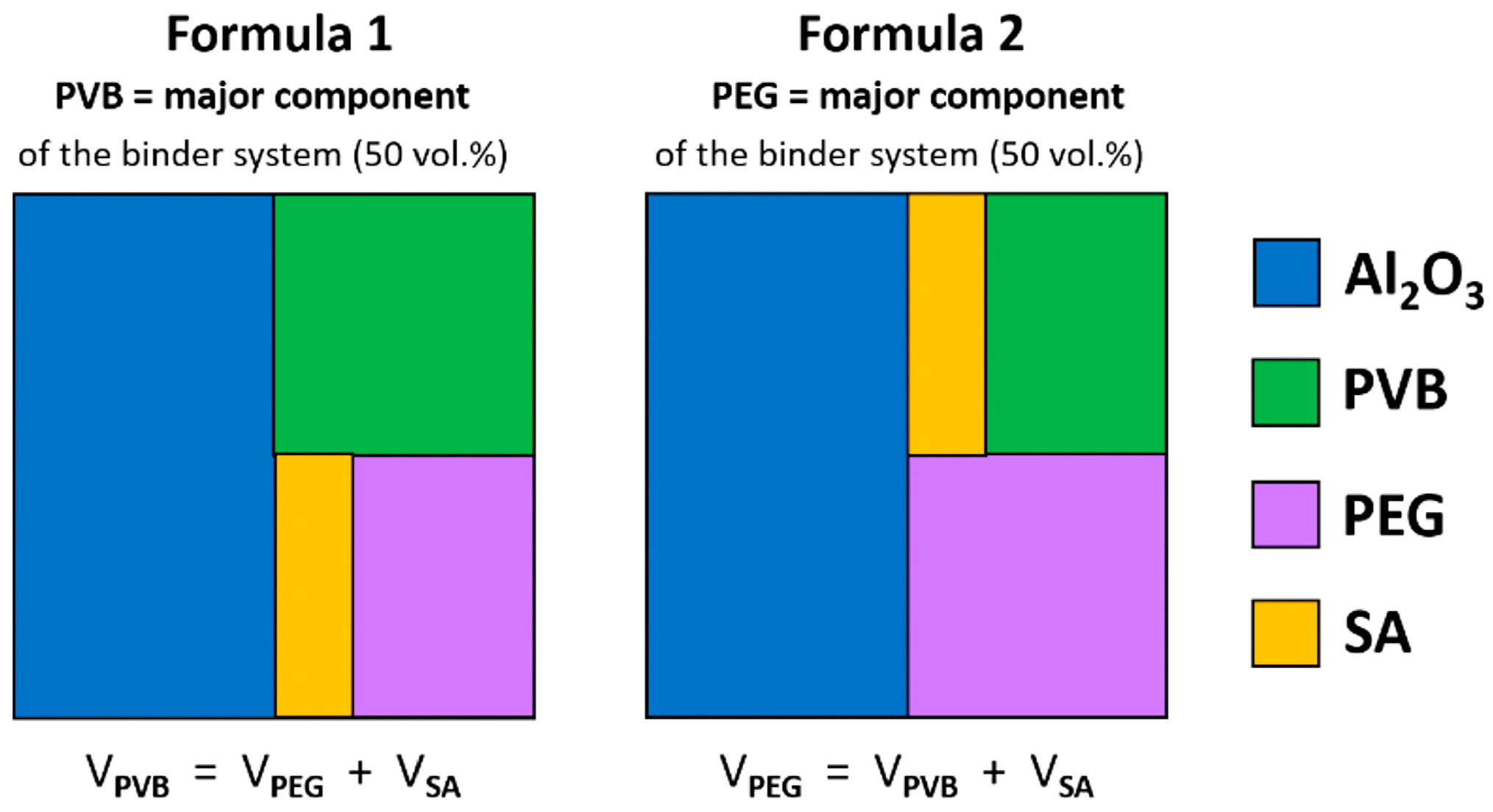
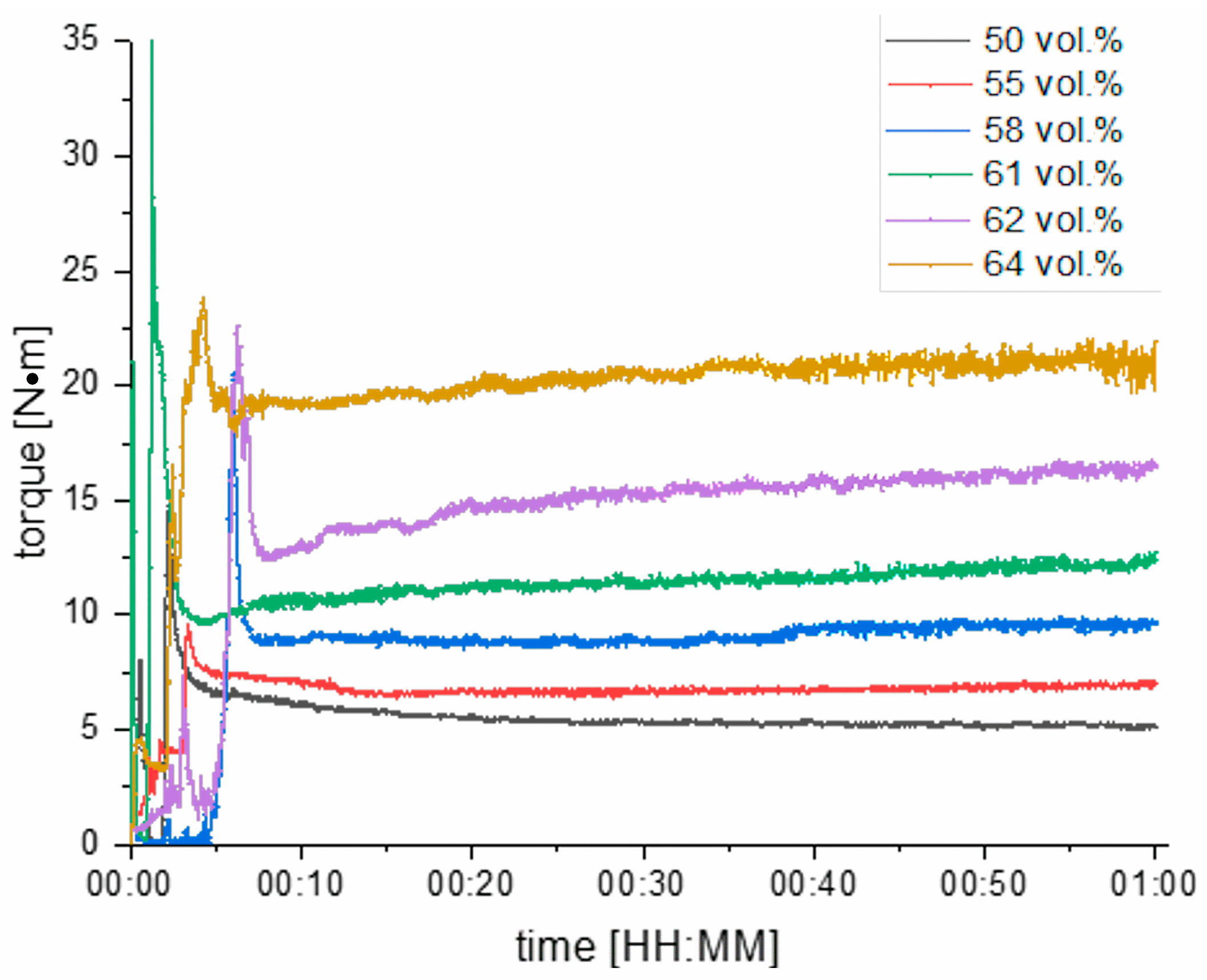
In this work, PVB/PEG-based alumina feedstocks were investigated rheologically in terms of their solid load and the PVB:PEG ratio. Injected parts usually contain between 35 and 50 vol.% organic binder [
9]. Feedstocks with powder loadings >50 vol.% (highly filled) were prepared using two different feedstock formulations (F1 and F2). F1-feedstocks contain PVB as the major fraction (50 vol.% of the binder system) while F2-feedstocks contain PEG as the major fraction of the binder. F1 feedstocks were investigated for alumina loads up to 64 vol.%. F2-feedstocks were tested for 55 and 58 vol.% alumina loads. The effects of the powder filling degree and the PVB:PEG ratio on kneading torque, the viscosity and the emerging shear stresses of the multi-material compound at a processing temperature of 160 °C are presented in this paper.
2. Materials and Methods
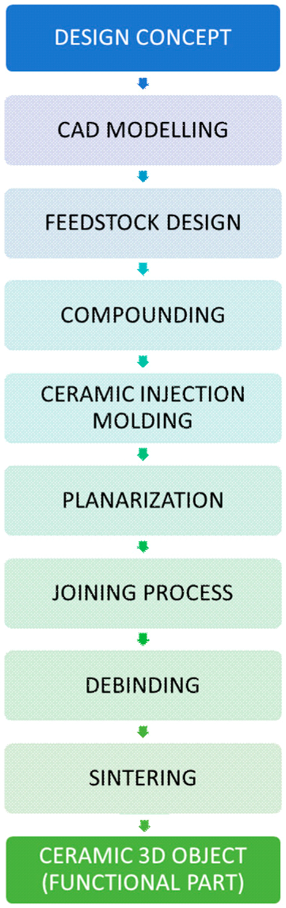
The ceramic microreactors for CHTS were fabricated according to the process chain depicted in
Figure 1. A design concept for a flow-type microreactor with a simple T-mixer was developed by CAD modelling. Appropriate molding inserts were fabricated out of brass by micromilling. Several molding compounds with variations of the components’ quantities were prepared, investigated rheometrically, thermogravimetrically, dilatometrically and further processed via CIM. The temperature program for the subsequent thermal posttreatment (especially the heating rates for debinding) was tailored specifically to the components’ size.
2.1. Design Concept for the Microreactor
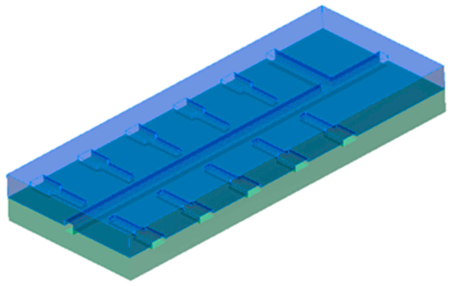
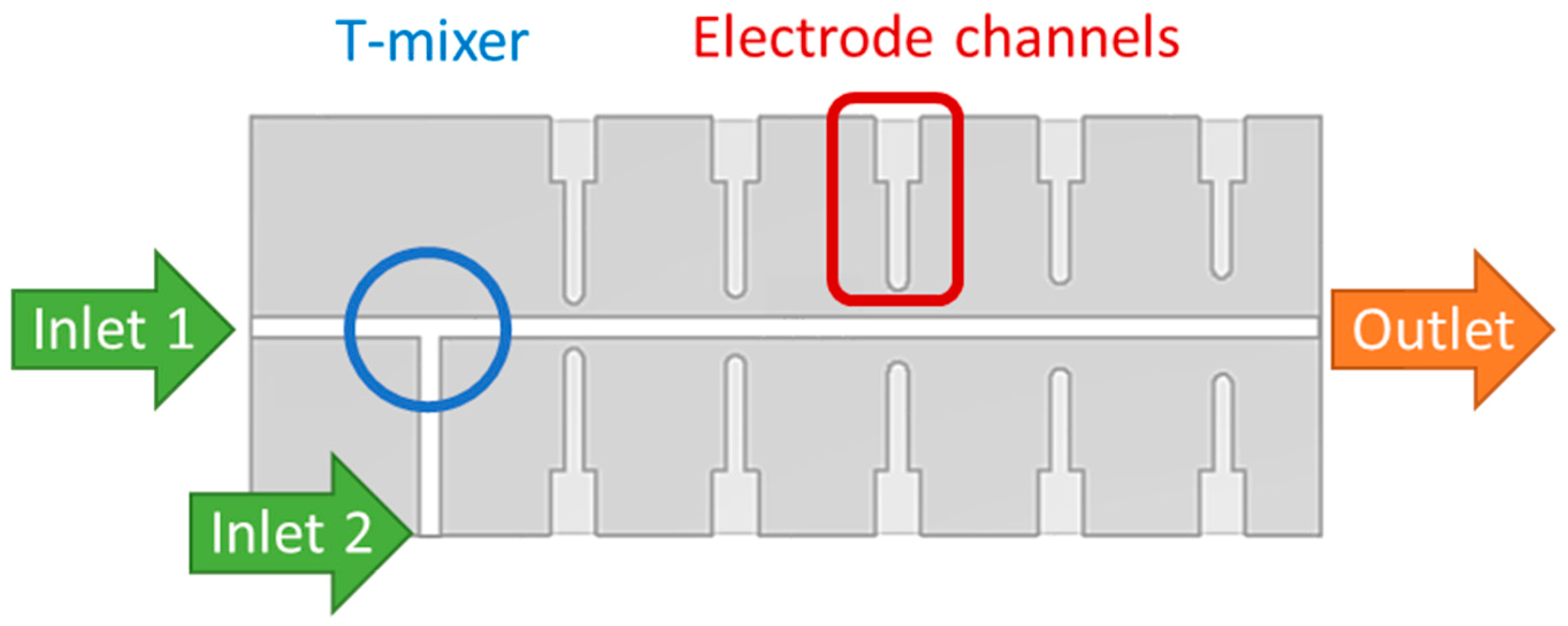
The microreactor is composed of two structured parts that have to be joined after the shaping process. Its structure consists of two inlet channels connected through a T-mixer to the reaction channel on which both sides five pairs of electrode channels are positioned at a maximum distance from each other.
Figure 2 and
Figure 3 depict the reactors’ design schematically and describe the functions of the channel structures.
2.2. Feedstock Design
The reactor material has to meet certain requirements to be suited for a CHTS. It must be chemically inert against aqueous metal salt solutions and also long-term resistant against supercritical water (sc-H
2O). It requires a high pressure, corrosion and flow abrasion resistance, and besides, it should exhibit a low permittivity and it needs to be electrically non-conductive to avoid short circuits between the electrodes of the sensor system. Through the use of a high performance ceramic as a reactor material, wear protection can be achieved for the relevant conditions. Alumina is a high performance ceramic and is long-term hydrothermal resistant at high temperatures [
27]. We used the fine-milled, sub-micron-sized alumina powder Martoxid
® MR70 (99.8% Al
2O
3, 0.08% SiO
2, 0.06% MgO, Martinswerk
®, Bergheim, Germany) with a mean particle size (d
50) of 0.5 to 0.8 µm (d
90 < 3 µm) and a specific surface (A
sp) of 8.6 m
2/g. The same alumina powder was used with a commercially available multi-component PE-based binder (Licomont EK 583-G, Clariant, Pratteln, Switzerland) in 2011 by Hausnerova et al. [
5].
The alumina powder was mixed with several organic vehicles to get a well-suited molding compound for the CIM process. Polyvinyl butyral (PVB, Mowital B30 H, Kuraray Europe GmbH, Hattersheim am Main, Germany) was used as the structural polymer (M
n = 2.12 × 10
4 g/mol). Polyethylene glycol (PEG 4000, Roth GmbH, Karlsruhe, Germany) was used as the basic polymer of the binder system. Stearic acid (Roth GmbH) was used as dispersant to achieve a steric stabilization of the alumina powder particles inside of the binder matrix. Its ratio was fixed to 4.4 mg/m
2 of the powder surface.
Figure 4 shows the two different PVB:PEG ratios that were investigated. The alumina content was varied from 50 vol.% up to 64 vol.% for Formula 1.
2.3. Compounding and Characterisation
All components were mixed at 125 °C in a measuring mixer (Plastograph, Brabender GmbH, Duisburg, Germany) for 1 h with 30 rpm. The molding compounds were characterized rheologically at a temperature of 160 °C which complies with the CIM processing temperature using a capillary rheometer (Rheograph 25, Göttfert GmbH, Buchen, Germany) with a nozzle diameter of 1 mm and a length-to-diameter (L/D) ratio of capillary of 30.
2.4. Ceramic Injection Molding
Reactor green bodies were fabricated from molding compounds with 55 and 58 vol.% Al
2O
3 using an injection molding machine (ELECTRA 50S, Ferromatik Milacron, Malterdingen, Germany) using micro-milled molding inserts made of brass. The parameters used for CIM are listed in
Table 1. The injection speed is matched to the size and shape of the molded part and should generally be fast. However, to avoid contamination of the compound due to abrasion, the injection speed was set to 100 mm/s. To facilitate the demolding process, a silicone-free release agent (Z 265, Hasco, Lüdenscheid, Germany) was used to avoid the molded part sticking to the molding inserts’ surface. The holding pressure is required to control the dimensional stability [
5].
2.5. Planarization
Before the two injection molded reactor parts were joined, the single green bodies were planarized thermally to cancel out any deformations or deflections that originate from the demolding step of the CIM process. For a reliable joint, the two parts must be completely plane-parallel to each other. Optically flat and uniformly even green bodies were obtained when they were heated up to 120 °C for 2 h between two alumina sintering plates (10 × 10 mm2).
2.6. Joining Process
The two reactor parts can be joined in their green state through dissolving the surfaces to be joined of both parts. Therefore, the green bodies’ structured surfaces were dissolved with isopropanol for a duration of 1 min to dissolve only a few microns of the surface. It was observed that longer residence times cause a loss of material at the joining seam since the compound mass that is partially dissolved at the surfaces becomes so soft that it is pushed easily out to the sides when the parts are stacked and pressed together. That is why dissolving the surfaces too deep leads to an unwelcome slot at the joining seam in the sintered body.
To achieve a properly sealed connection of the joining parts, it is necessary to perform the joining process with short residence times for the surface dissolving procedure and without much pressure. When the top and the bottom sections of the reactor are exactly on top of each other, they can be pressed together carefully. It is also possible to use ethanol as a solvent for the PVB-/PEG-compound. However, it must be taken into account that ethanol dissolves the green bodies’ surfaces even faster than isopropanol. Thus, it is recommended to join the parts immediately after wetting the surfaces with ethanol to hamper a loss of material along the joining seam.
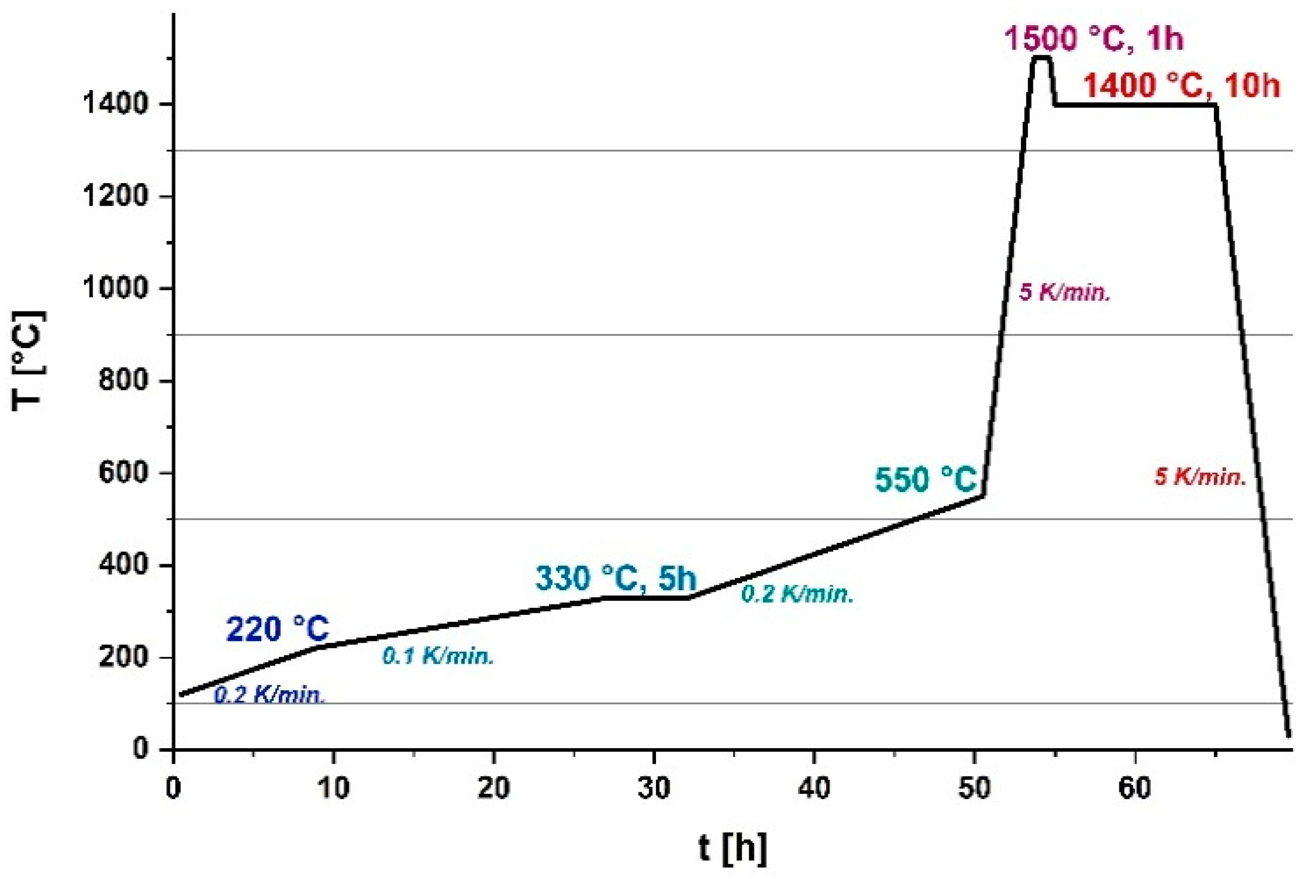
2.7. Debinding Process
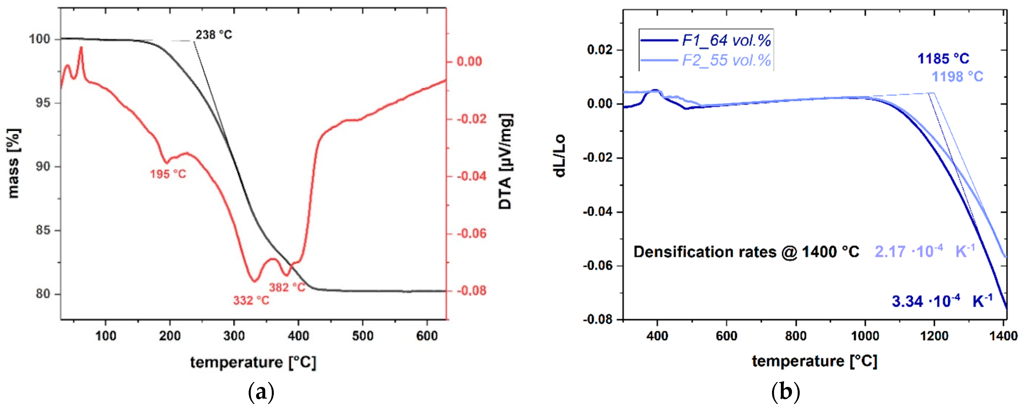
The thermal post-treatment process starts with a very slow combustion step where the organic components are burned out. To develop a suited temperature program for a smooth combustion of the PVB-/PEG-based binder without causing any defects in the ceramic microstructure, the thermal behavior of the molding compound that was used for manufacturing the microreactor parts (F2 with 55 vol.% powder loading) was investigated by thermal gravimetric analysis (STA 409, Netzsch, Selb, Germany). The stacked reactor parts were debound in a debinding furnace (HT6/28, Carbolite GmbH, Neuhausen, Germany) on top of an alumina sintering plate. Heating rates, holding temperatures as well as dwells were iteratively varied to develop a temperature program that also fits to the reactors’ size and factors in the thicknesses of 4 mm of each reactor part. Smaller components, like tribology disks, made of the same molding compound can be debound with much higher heating rates up to 5 K/min. since their aspect ratio is also higher than the one of the reactor assembly.
2.8. Sintering Process
Dilatometric measurements (Dil 402C, Netzsch, Germany) were applied to ceramic feedstocks with 55 vol.% as well as 64 vol.% powder load to determine the temperature at which the sintering process starts. The debound parts (brown bodies) were sintered in a sintering furnace (RHF 17/3, Carbolite, Germany) using a two-step-sintering process suggested by Chen and Wang (TSS-CW) to obtain ceramic bodies with a controlled microstructure [
28]. The TSS technique is applied to create a fine-grained ceramic microstructure by suppressing the accelerated grain growth, which usually occurs in the final sintering stage, however it still allows densification to occur. The technique may thus enable high-density microstructure refinement and improve several properties of the materials. The applicability of the TSS technique as a means of suppressing the final stage grain growth was verified by Bodišová et al. for a sub-micrometer alumina powder (mean particle size = 200 nm) [
29]. They yielded a high densification degree (ρ
rel = 98.8%) without any significant grain growth (mean grain size = 0.9 µm) with the TSS sintering plan: T1 at 1400–1450 °C and T2 at 1150 °C. Thereby, the first heating step T1 should be short at a relatively high-temperature in order to close porosity without significant grain growth. The second step T2 facilitates further densification with limited grain growth. The effect of heating rate was also examined.
Both density and grain size were lower if faster heating was applied. Kim and Kishi studied the effect of TSS on the resistance and the subcritical crack growth in alumina and found out that it led to decreased grain growth and a more homogenous microstructure which increased the fracture toughness of the grain boundary, resulting in strengthening the material resistance [
30].
For sintering the reactor components during the course of this work, slightly higher temperatures for T1 and T2 were used than recommended by Bodišová et al. to address their larger size (8 × 26 × 66 mm3) in comparison to common specimens. T1 was set to 1500 °C and T2 to 1400 °C, while the holding times were varied. Before further processing of the sintered microreactor parts (applying electrodes for the sensor system to be integrated), it is necessary to check if the reactor channel is sealed. Possible residual leaks were capped through repeated painting (or using a dipping bath) of the sintered body into the commercial water-based impregnating agent for castings and RapidPrototyping models Nano-Seal 180W® (JELN Imprägnierung GmbH, Schwalmtal, Germany). Nano-Seal 180W® has a low viscosity and is thus able to penetrate into the pores due to capillary forces. It seals permanently elastic, so that the seal, which is additionally non-combustible, complies with the DIN EN 161 (tightness in gas valves).
4. Conclusions
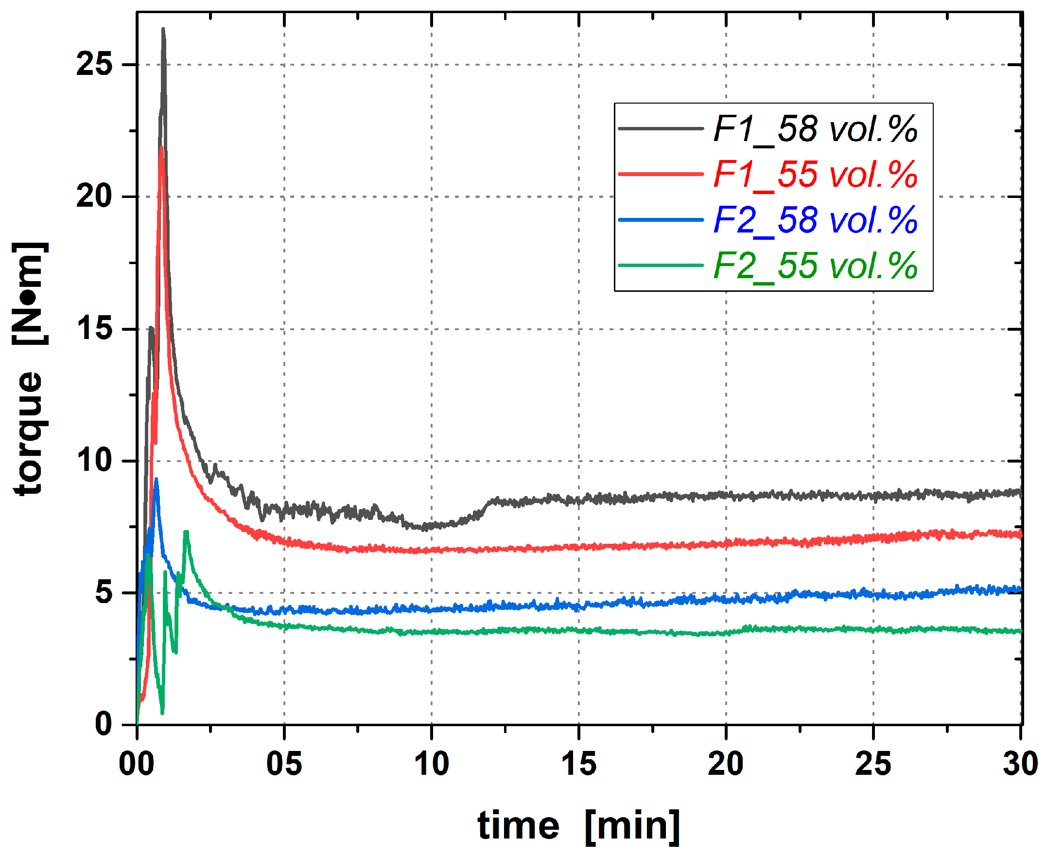
In this study, the rheological and thermal properties of CIM alumina feedstocks based on different ratios of the organic additives PVB and PEG were investigated to gain knowledge about their effect on the feedstocks’ viscosities and their pseudo-plasticity of highly filled molding compounds. Therefore, the filler content was also varied. As a result, it was shown that powder loads up to 64 vol.% can be realized even for the feedstocks containing more PVB than PEG, which makes them generally more viscous than feedstocks with higher PEG content. However, to ensure a robust manufacturing process including complete homogenization of the feedstocks components, complete cavity filling during injection as well as a good dimensional stability of the ceramic green bodies during demolding and debinding, filling degrees of 55 vol.% and 58 vol.% were selected for further investigations on the binder system and the CIM of alumina microreactors for CHTS.
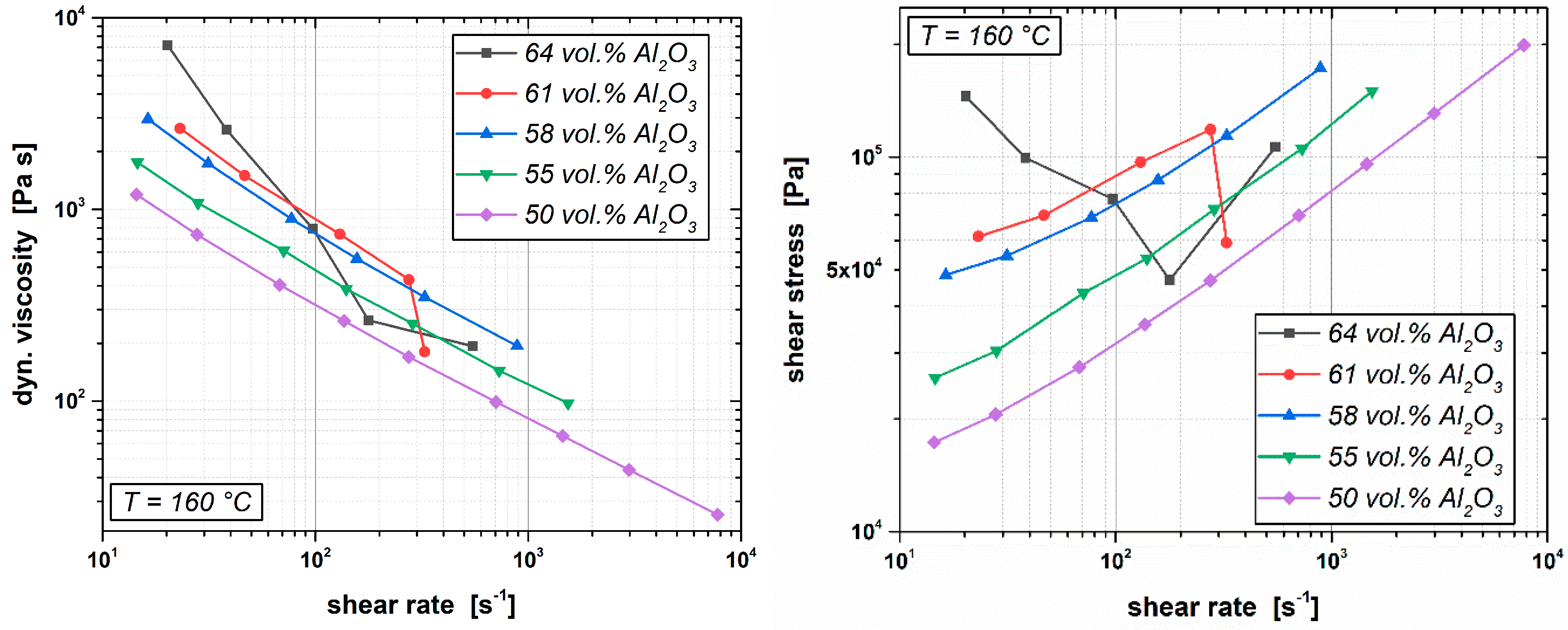
The comparison of different formulations of PVB-/PEG-based CIM feedstocks shows that the low molecular binder component, PEG 4000, provides very low feedstocks viscosities at operating conditions of highly filled alumina compounds and, concurrently, sufficient mechanical strength of the molded green bodies at reduced temperatures. PEG 4000 can thus be used as the main share of the binder system without losing the required dimensional stability of the ceramic part. It was shown that the feedstocks viscosity at low share rates of 102 s−1 and a processing temperature of 160 °C could be reduced from 499 Pa·s to 32 Pa·s (for the feedstock containing 55 vol.% alumina powder) and from 798 Pa·s down to 58 Pa·s (for a powder load of 58 vol.%) only by increasing the PEG content at the expense of the backbone polymer PVB. Furthermore, it was observed that adjusting the PVB-/PEG ratio is an applicable key to customize the flow behavior of ceramic feedstocks.
Using the calculated flow consistency indices and flow behavior indices as a measure for the feedstocks pseudo-plasticity revealed that increasing the PEG content reduces the shear rate dependence significantly towards a more Newtonian flow behavior. In summary, it can be ascertained that feedstocks according to formula F1, containing more PVB than PEG, can be recommended for CIM of ceramic parts where the dimensional stability of the molded parts is challenging. However, massive part geometries with sufficient wall thicknesses can also be successfully manufactured using feedstocks according to formula F2, containing more PEG than PVB. These feedstocks have the advantage of providing very low feedstocks’ viscosities, which is desired to facilitate the cavity filling of challenging part geometries (high aspect ratios) with less injection pressure, which also means less abrasion and the potential for higher powder loadings.


