Manufacturing and Analysis of High-Performance Refractory High-Entropy Alloy via Selective Laser Melting (SLM)

Abstract

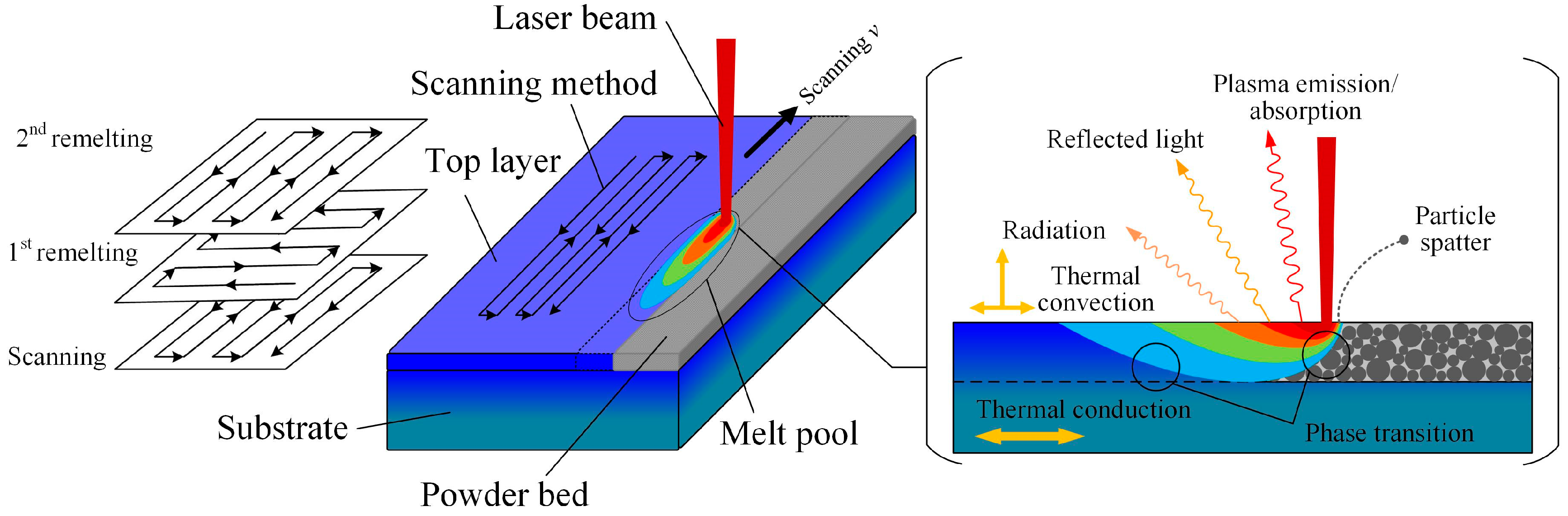
1. Introduction
2. Material and Methods
3. Results and Discussion
3.1. Experimental Powders
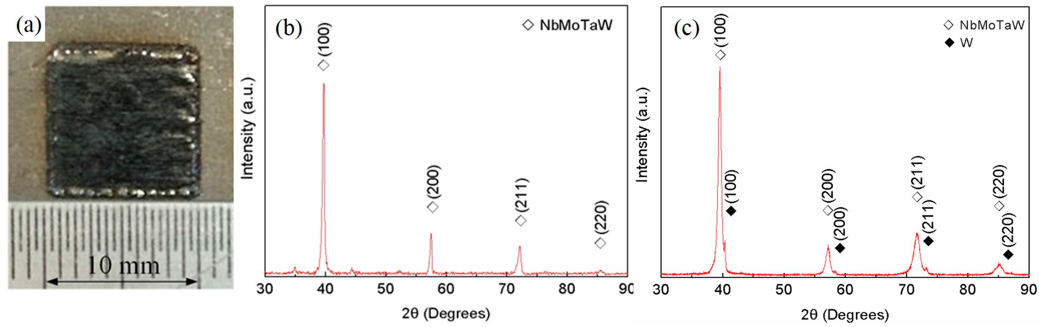
3.2. Phase and Composition
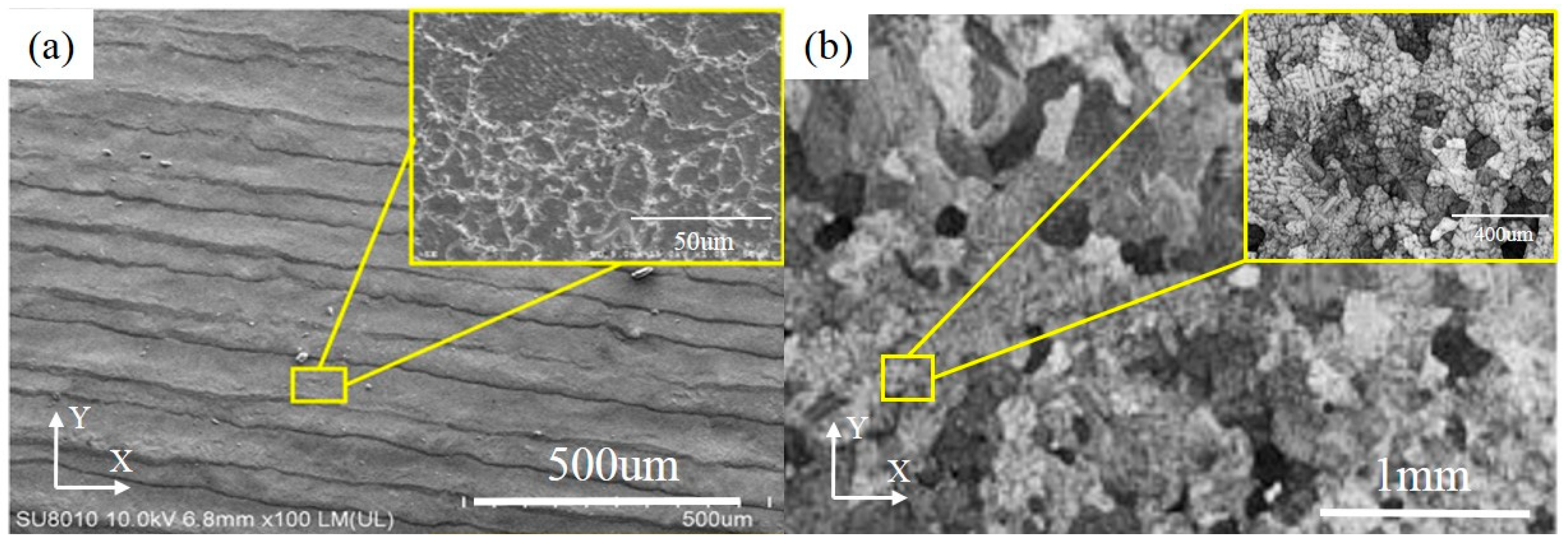
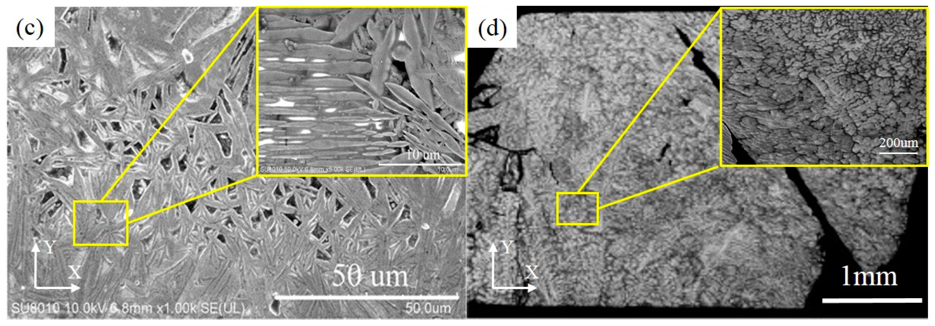
3.3. Microstructure
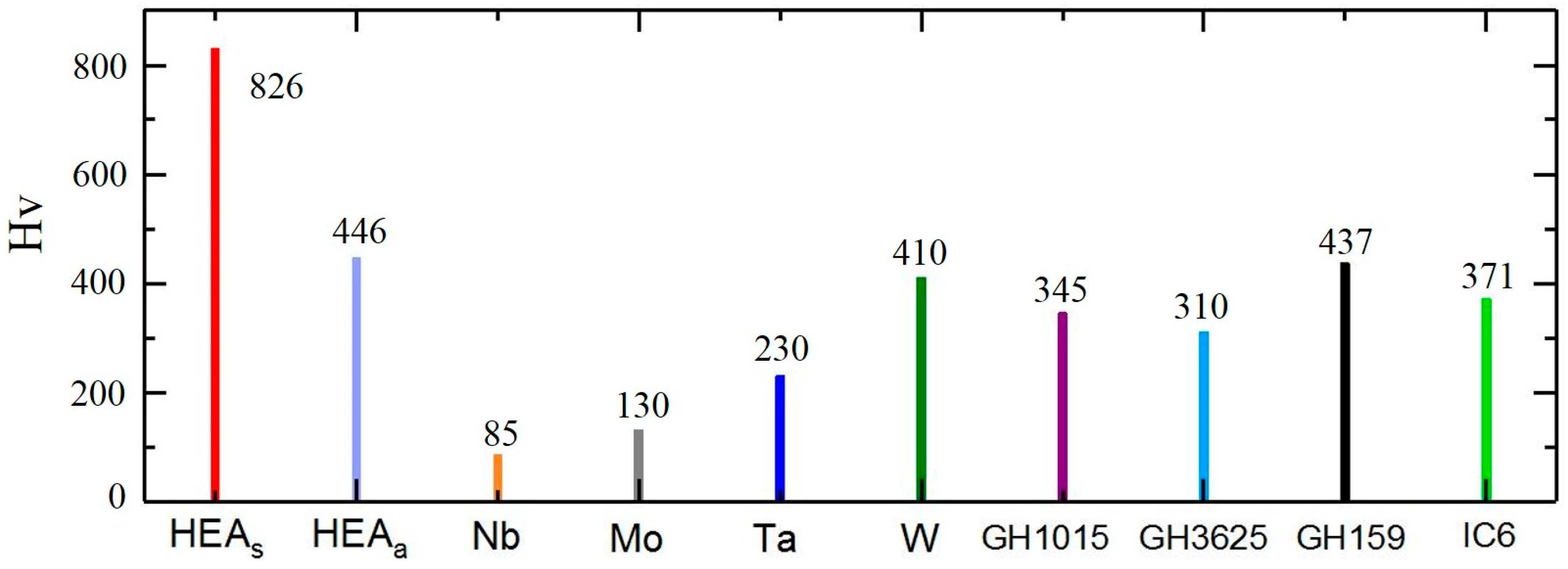
3.4. Microhardness
3.5. Corrosion Resistance
4. Conclusions
Author Contributions
Acknowledgments
Conflicts of Interest
References
- Yeh, J.W.; Chen, S.K.; Lin, S.J.; Gan, J.Y.; Chin, T.S.; Shun, T.T.; Tsau, C.-H.; Chang, S.-Y. Nanostructured High-Entropy Alloys with Multiple Principal Elements: Novel Alloy Design Concepts and Outcomes. Adv. Eng. Mater. 2004, 6, 299–303. [Google Scholar] [CrossRef]
- Jien-Wei, Y. Recent progress in high entropy alloys. Ann. Chim. Sci. Mater. 2006, 31, 633–648. [Google Scholar]
- Cantor, B.; Chang, I.; Knight, P.; Vincent, A. Microstructural development in equiatomic multicomponent alloys. Mater. Sci. Eng. A 2004, 375, 213–218. [Google Scholar] [CrossRef]
- Zhang, Y.; Yang, X.; Liaw, P.K. Alloy design and properties optimization of high-entropy alloys. JOM 2012, 64, 830–838. [Google Scholar] [CrossRef]
- Yeh, J. Alloy design strategies and future trends in high-entropy alloys. JOM 2013, 65, 1759–1771. [Google Scholar] [CrossRef]
- Zhang, Y.; Zuo, T.T.; Tang, Z.; Gao, M.C.; Dahmen, K.A.; Liaw, P.K.; Lu, Z.P. Microstructures and properties of high-entropy alloys. Prog. Mater. Sci. 2014, 61, 1–93. [Google Scholar] [CrossRef]
- Gao, J.; Li, R. The microstructure and heat-resistance of AlZnMnSnSbPbMg high-entropy alloy. J. Funct. Mater. 2009, 4, 21. [Google Scholar]
- Zhang, Y.; Zuo, T.; Cheng, Y.; Liaw, P.K. High-entropy alloys with high saturation magnetization, electrical resistivity, and malleability. Sci. Rep. 2013, 3, 1455. [Google Scholar] [CrossRef] [PubMed]
- Gludovatz, B.; Hohenwarter, A.; Catoor, D.; Chang, E.H.; George, E.P.; Ritchie, R.O. A fracture-resistant high-entropy alloy for cryogenic applications. Science 2014, 345, 1153–1158. [Google Scholar] [CrossRef] [PubMed]
- Gao, M.C.; Alman, D.E. Searching for next single-phase high-entropy alloy compositions. Entropy 2013, 15, 4504–4519. [Google Scholar] [CrossRef]
- Senkov, O.N.; Wilks, G.B.; Scott, J.M.; Miracle, D.B. Mechanical properties of Nb25Mo25Ta25W25 and V20Nb20Mo20Ta20W20 refractory high entropy alloys. Intermetallics 2011, 19, 698–706. [Google Scholar] [CrossRef]
- Senkov, O.N.; Wilks, G.B.; Miracle, D.B.; Chuang, C.P.; Liaw, P.K. Refractory high-entropy alloys. Intermetallics 2010, 18, 1758–1765. [Google Scholar] [CrossRef]
- Zou, Y.; Ma, H.; Spolenak, R. Ultrastrong ductile and stable high-entropy alloys at small scales. Nat. Commun. 2015, 6, 7748. [Google Scholar] [CrossRef] [PubMed]
- Zhang, M.; Zhou, X.; Yu, X.; Li, J. Synthesis and characterization of refractory TiZrNbWMo high-entropy alloy coating by laser cladding. Surf. Coat. Technol. 2017, 311, 321–329. [Google Scholar] [CrossRef]
- Joseph, J.; Stanford, N.; Hodgson, P.; Fabijanic, D.M. Tension/compression asymmetry in additive manufactured face centered cubic high entropy alloy. Scr. Mater. 2017, 129, 30–34. [Google Scholar] [CrossRef]
- Kunce, I.; Polanski, M.; Bystrzycki, J. Structure and hydrogen storage properties of a high entropy ZrTiVCrFeNi alloy synthesized using Laser Engineered Net Shaping (LENS). Int. J. Hydrogen. Energy 2013, 38, 12180–12189. [Google Scholar] [CrossRef]
- Kunce, I.; Polanski, M.; Bystrzycki, J. Microstructure and hydrogen storage properties of a TiZrNbMoV high entropy alloy synthesized using Laser Engineered Net Shaping (LENS). Int. J. Hydrogen. Energy 2014, 39, 9904–9910. [Google Scholar] [CrossRef]
- Dobbelstein, H.; Thiele, M.; Gurevich, E.L.; George, E.P.; Ostendorf, A. Direct metal deposition of refractory high entropy alloy MoNbTaW. Phys. Procedia 2016, 83, 624–633. [Google Scholar] [CrossRef]
- Wang, R.; Zhang, K.; Davies, C.; Wu, X. Evolution of microstructure, mechanical and corrosion properties of AlCoCrFeNi high-entropy alloy prepared by direct laser fabrication. J. Alloys Compd. 2017, 694, 971–981. [Google Scholar] [CrossRef]
- Tolochko, N.K.; Khlopkov, Y.V.; Mozzharov, S.E.; Ignatiev, M.B.; Laoui, T.; Titov, V.I. Absorptance of powder materials suitable for laser sintering. Rapid Prototyp. J. 2000, 6, 155–161. [Google Scholar] [CrossRef]
- GB/T 6394-2002, Method for Measuring Average Grain Size of Metals; Standardization and Quality of Machinery Industry: Beijin, China, 2004.
- Hall, E.O. The deformation and ageing of mild steel: III discussion of results. Proc. Phys. Soc. B 1951, 64, 747. [Google Scholar] [CrossRef]
- Petch, N.J. The cleavage strength of polycrystals. J. Iron Steel Inst. 1953, 174, 25–28. [Google Scholar]
- Armstrong, R.W. The influence of polycrystal grain size on several mechanical properties of materials. Metall. Mater. Trans. 1970, 1, 1169–1176. [Google Scholar] [CrossRef]
- Shabalin, I.L. Ultra-High Temperature Materials, 1st ed.; Springer: New York, NY, USA, 2014; pp. 237–531. [Google Scholar]
- Anonymous. Practical Handbook of Engineering Materials. 2. Practical Handbook of Deformed Superalloy and Cast Superalloy, 2nd ed.; Standards Press of China: Beijing, China, 2002; pp. 9–829. [Google Scholar]


| Element | S1 (at%) | S2 (at%) | S3 (at%) | Avg. (at%) | Variance |
|---|---|---|---|---|---|
| W | 27.26 | 24.76 | 24.35 | 25.46 | 1.65 |
| Ta | 28.09 | 29.49 | 27.06 | 28.21 | 0.99 |
| Nb | 21.61 | 20.97 | 21.93 | 21.50 | 0.16 |
| Mo | 23.05 | 24.79 | 26.67 | 24.84 | 2.19 |
© 2019 by the authors. Licensee MDPI, Basel, Switzerland. This article is an open access article distributed under the terms and conditions of the Creative Commons Attribution (CC BY) license (http://creativecommons.org/licenses/by/4.0/).
Share and Cite
Zhang, H.; Zhao, Y.; Huang, S.; Zhu, S.; Wang, F.; Li, D. Manufacturing and Analysis of High-Performance Refractory High-Entropy Alloy via Selective Laser Melting (SLM). Materials 2019, 12, 720. https://doi.org/10.3390/ma12050720
Zhang H, Zhao Y, Huang S, Zhu S, Wang F, Li D. Manufacturing and Analysis of High-Performance Refractory High-Entropy Alloy via Selective Laser Melting (SLM). Materials. 2019; 12(5):720. https://doi.org/10.3390/ma12050720
Chicago/Turabian StyleZhang, Hang, Yizhen Zhao, Sheng Huang, Shuo Zhu, Fu Wang, and Dichen Li. 2019. "Manufacturing and Analysis of High-Performance Refractory High-Entropy Alloy via Selective Laser Melting (SLM)" Materials 12, no. 5: 720. https://doi.org/10.3390/ma12050720
APA StyleZhang, H., Zhao, Y., Huang, S., Zhu, S., Wang, F., & Li, D. (2019). Manufacturing and Analysis of High-Performance Refractory High-Entropy Alloy via Selective Laser Melting (SLM). Materials, 12(5), 720. https://doi.org/10.3390/ma12050720