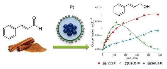
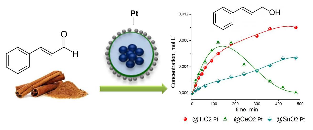
Magnetic Fe2O3–SiO2–MeO2–Pt (Me = Ti, Sn, Ce) as Catalysts for the Selective Hydrogenation of Cinnamaldehyde. Effect of the Nature of the Metal Oxide

Abstract
1. Introduction
2. Materials and Methods
2.1. Materials
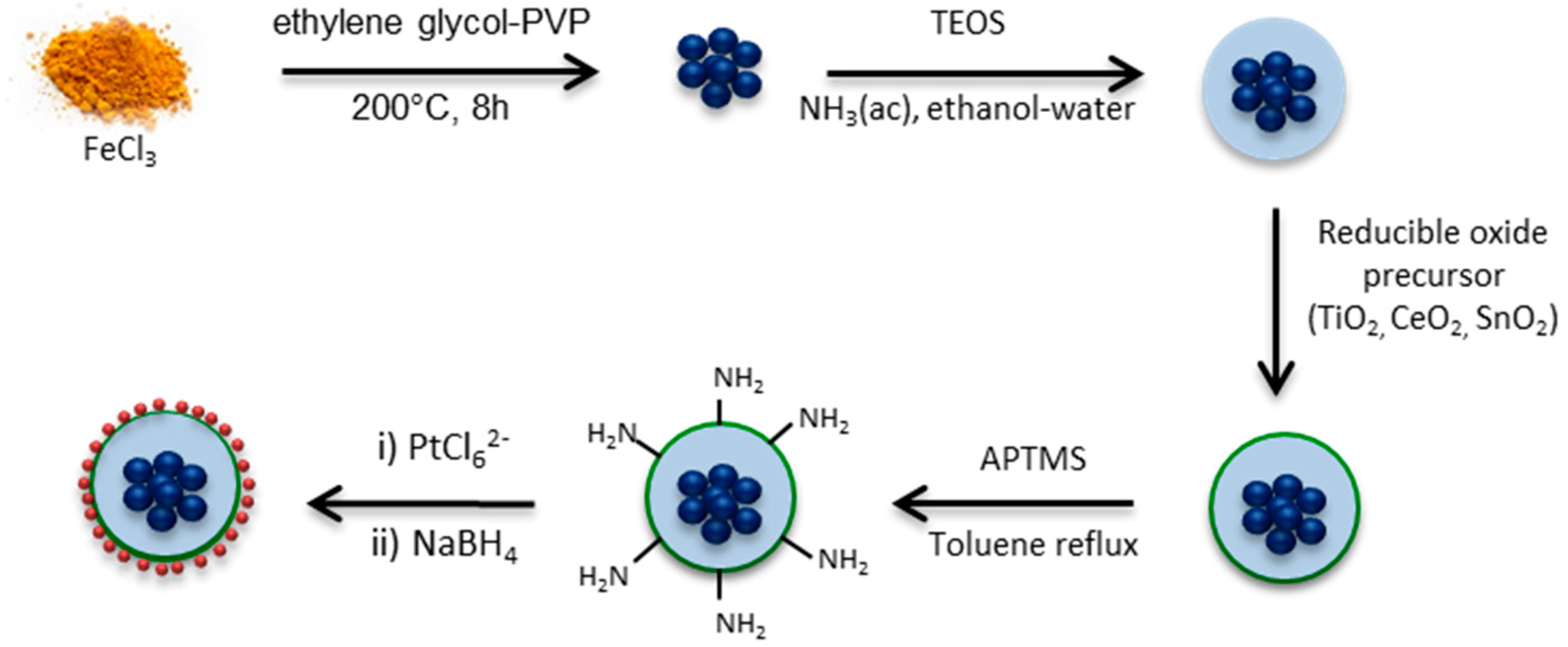
2.2. Fe3O4–SiO2 Structure
2.3. Fe2O3–SiO2 and Fe2O3–SiO2–MeO2 (Me = Ti, Sn, Ce) Structures
2.4. Fe2O3–SiO2–MeO2–Pt (Me = Ti, Sn, Ce) Catalysts
2.5. Characterization
2.6. Catalytic Activity
3. Results and Discussion
3.1. Material Synthesis
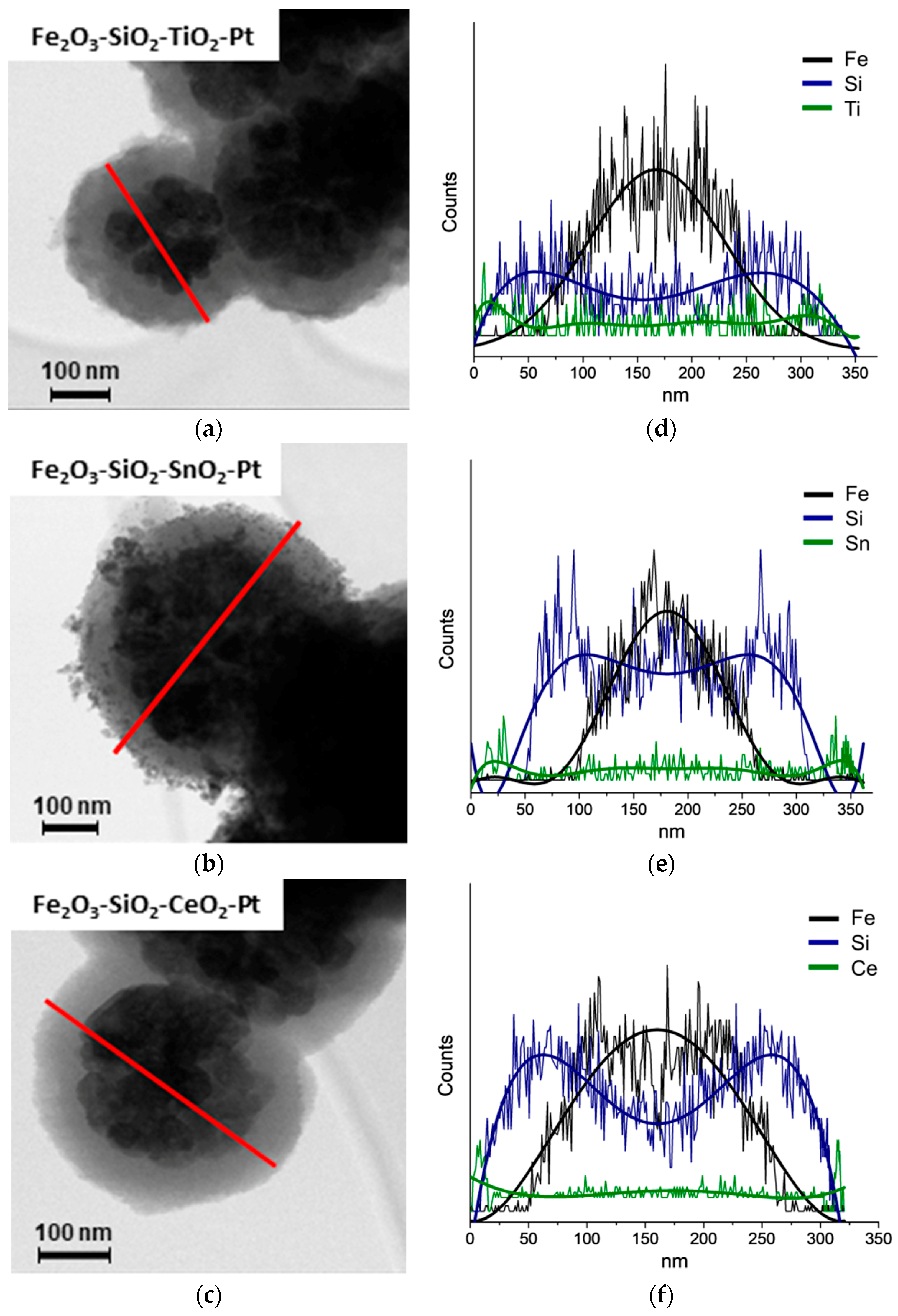
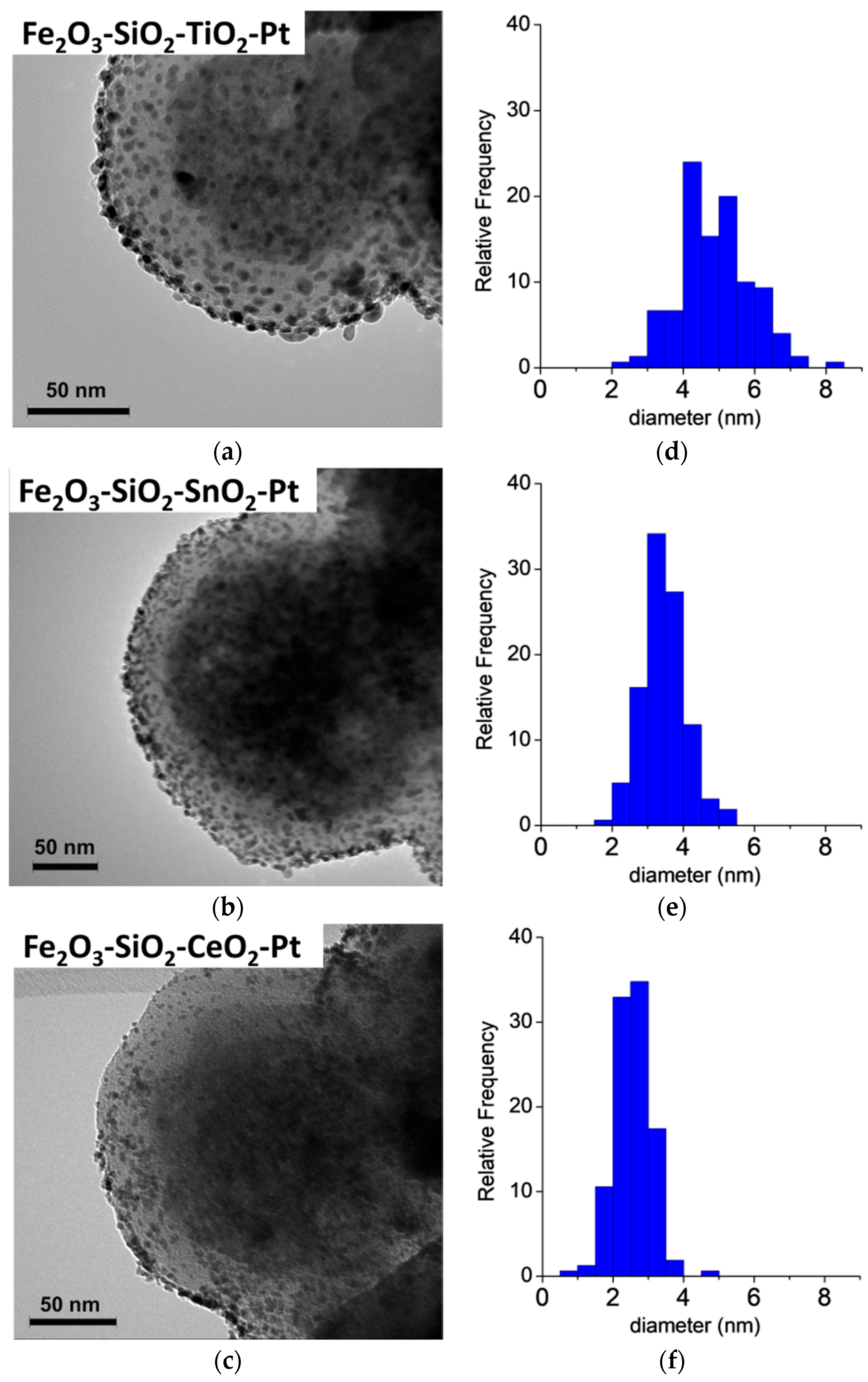
3.2. HR-TEM
3.3. ICP
3.4. Specific Area
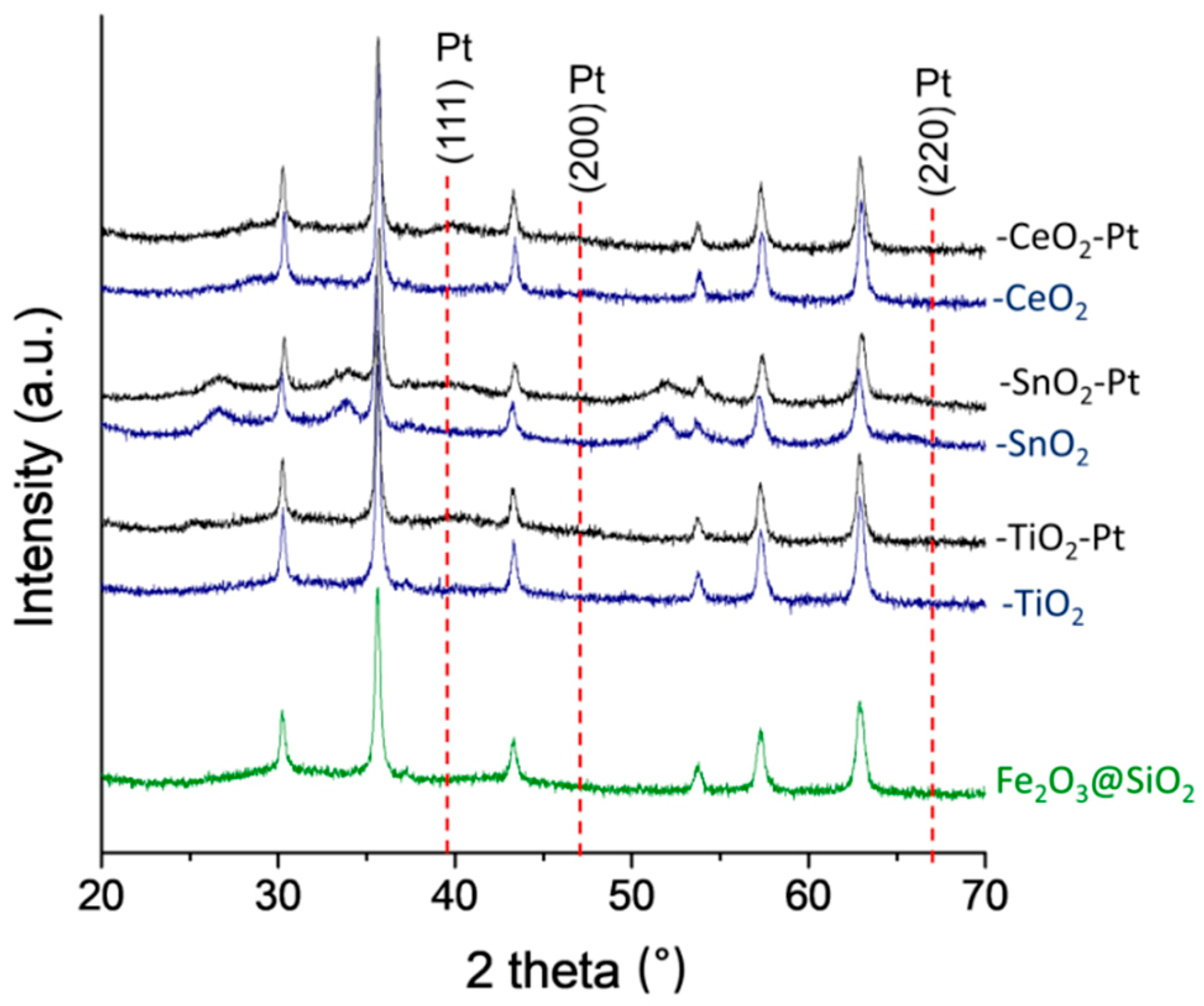
3.5. XRD
3.6. TPR-H2
3.7. Magnetic Measurements
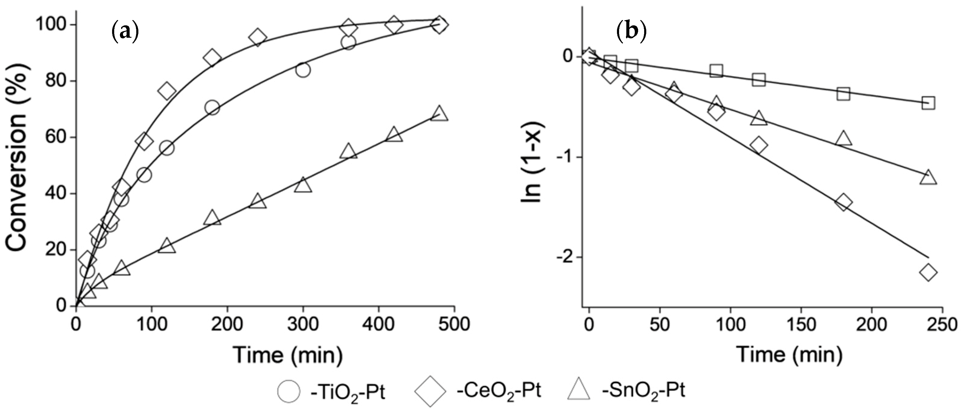
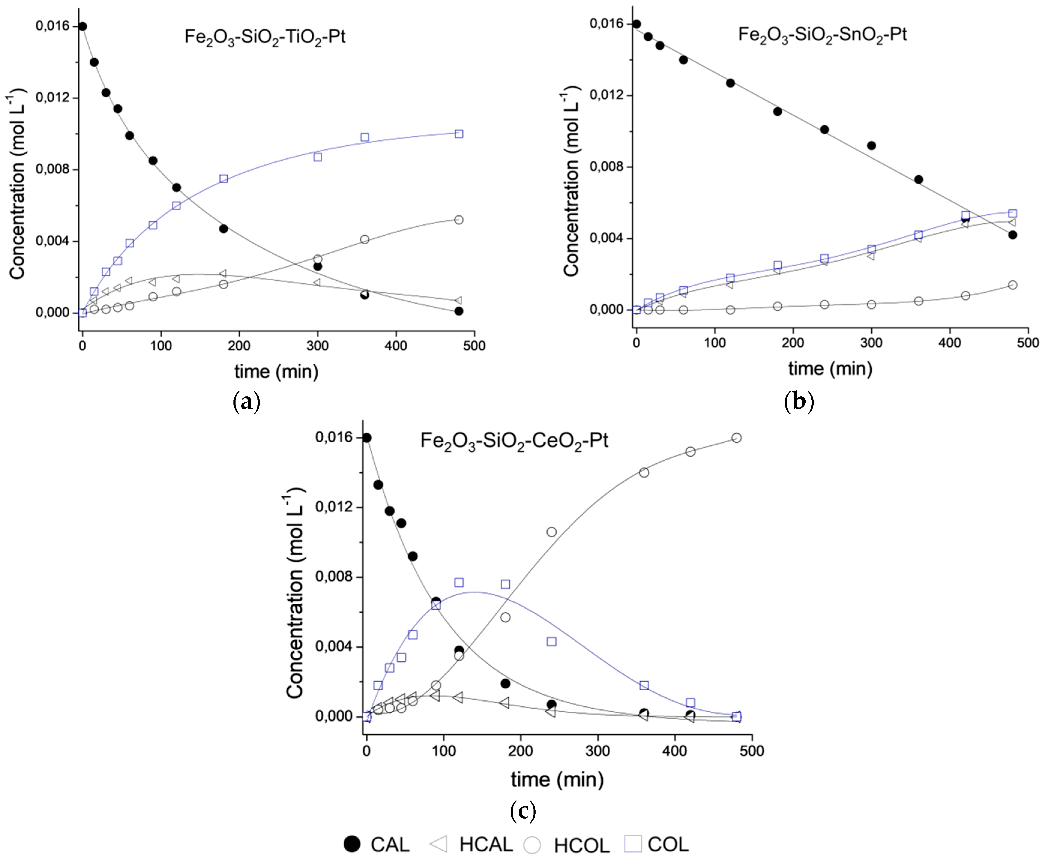
3.8. Catalytic Performance
4. Conclusions
Supplementary Materials
Author Contributions
Funding
Acknowledgments
Conflicts of Interest
References
- Lee, C.H.; Ma, Y.; Jang, K.-I.; Banks, A.; Pan, T.; Feng, X.; Kim, J.S.; Kang, D.; Raj, M.S.; McGrane, B.L.; et al. Soft Core/Shell Packages for Stretchable Electronics. Adv. Funct. Mater. 2015, 25, 3698–3704. [Google Scholar] [CrossRef]
- Akbarzadeh, A.; Samiei, M.; Davaran, S. Magnetic nanoparticles: Preparation, physical properties, and applications in biomedicine. Nanoscale Res. Lett. 2012, 7, 144. [Google Scholar] [CrossRef] [PubMed]
- Mondal, K.; Sharma, A. Recent advances in the synthesis and application of photocatalytic metal–metal oxide core–shell nanoparticles for environmental remediation and their recycling process. RSC Adv. 2016, 6, 83589–83612. [Google Scholar] [CrossRef]
- Ye, M.; Zhang, Q.; Hu, Y.; Ge, J.; Lu, Z.; He, L.; Chen, Z.; Yin, Y. Magnetically Recoverable Core–Shell Nanocomposites with Enhanced Photocatalytic Activity. Chem. Eur. J. 2010, 16, 6243–6250. [Google Scholar] [CrossRef] [PubMed]
- Joo, S.H.; Park, J.Y.; Tsung, C.-K.; Yamada, Y.; Yang, P.; Somorjai, G.A. Thermally stable Pt/mesoporous silica core–shell nanocatalysts for high-temperature reactions. Nat. Mater. 2008, 8, 126. [Google Scholar] [CrossRef] [PubMed]
- Ikeda, S.; Ishino, S.; Harada, T.; Okamoto, N.; Sakata, T.; Mori, H.; Kuwabata, S.; Torimoto, T.; Matsumura, M. Ligand-Free Platinum Nanoparticles Encapsulated in a Hollow Porous Carbon Shell as a Highly Active Heterogeneous Hydrogenation Catalyst. Angew. Chem. 2006, 118, 7221–7224. [Google Scholar] [CrossRef]
- Ghosh Chaudhuri, R.; Paria, S. Core/Shell Nanoparticles: Classes, Properties, Synthesis Mechanisms, Characterization, and Applications. Chem. Rev. 2012, 112, 2373–2433. [Google Scholar] [CrossRef] [PubMed]
- Fernandes, C.I.; Capelli, S.C.; Vaz, P.D.; Nunes, C.D. Highly selective and recyclable MoO3 nanoparticles in epoxidation catalysis. Appl. Catal. A 2015, 504, 344–350. [Google Scholar] [CrossRef]
- Claus, P. Selective hydrogenation of ά,β-unsaturated aldehydes and other C=O and C=C bonds containing compounds. Top. Catal. 1998, 5, 51–62. [Google Scholar] [CrossRef]
- Piqueras, C.M.; Puccia, V.; Vega, D.A.; Volpe, M.A. Selective hydrogenation of cinnamaldehyde in supercritical CO2 over Me–CeO2 (Me = Cu, Pt, Au): Insight of the role of Me–Ce interaction. Appl. Catal. B 2016, 185, 265–271. [Google Scholar] [CrossRef]
- Wu, Q.; Zhang, C.; Zhang, B.; Li, X.; Ying, Z.; Liu, T.; Lin, W.; Yu, Y.; Cheng, H.; Zhao, F. Highly selective Pt/ordered mesoporous TiO2–SiO2 catalysts for hydrogenation of cinnamaldehyde: The promoting role of Ti2+. J. Colloid Interface Sci. 2016, 463, 75–82. [Google Scholar] [CrossRef] [PubMed]
- Rong, Z.; Sun, Z.; Wang, Y.; Lv, J.; Wang, Y. Selective Hydrogenation of Cinnamaldehyde to Cinnamyl Alcohol over Graphene Supported Pt–Co Bimetallic Catalysts. Catal. Lett. 2014, 144, 980–986. [Google Scholar] [CrossRef]
- Laref, S.; Delbecq, F.; Loffreda, D. Theoretical elucidation of the selectivity changes for the hydrogenation of unsaturated aldehydes on Pt(111). J. Catal. 2009, 265, 35–42. [Google Scholar] [CrossRef]
- Zheng, Q.; Wang, D.; Yuan, F.; Han, Q.; Dong, Y.; Liu, Y.; Niu, X.; Zhu, Y. An Effective Co-promoted Platinum of Co–Pt/SBA-15 Catalyst for Selective Hydrogenation of Cinnamaldehyde to Cinnamyl Alcohol. Catal. Lett. 2016, 146, 1535–1543. [Google Scholar] [CrossRef]
- Hsu, C.-Y.; Chiu, T.-C.; Shih, M.-H.; Tsai, W.-J.; Chen, W.-Y.; Lin, C.-H. Effect of Electron Density of Pt Catalysts Supported on Alkali Titanate Nanotubes in Cinnamaldehyde Hydrogenation. J. Phys. Chem. C 2010, 114, 4502–4510. [Google Scholar] [CrossRef]
- Plomp, A.J.; Vuori, H.; Krause, A.O.I.; de Jong, K.P.; Bitter, J.H. Particle size effects for carbon nanofiber supported platinum and ruthenium catalysts for the selective hydrogenation of cinnamaldehyde. Appl. Catal. A 2008, 351, 9–15. [Google Scholar] [CrossRef]
- Helali, Z.; Jedidi, A.; Syzgantseva, O.A.; Calatayud, M.; Minot, C. Scaling reducibility of metal oxides. Theor. Chem. Acc. 2017, 136, 100. [Google Scholar] [CrossRef]
- Dai, L.-X.; Zhu, W.; Lin, M.; Zhang, Z.-P.; Gu, J.; Wang, Y.-H.; Zhang, Y.-W. Self-supported composites of thin Pt–Sn crosslinked nanowires for the highly chemoselective hydrogenation of cinnamaldehyde under ambient conditions. Inorg. Chem. Front. 2015, 2, 949–956. [Google Scholar] [CrossRef]
- Wei, S.; Zhao, Y.; Fan, G.; Yang, L.; Li, F. Structure-dependent selective hydrogenation of cinnamaldehyde over high-surface-area CeO2-ZrO2 composites supported Pt nanoparticles. Chem. Eng. J. 2017, 322, 234–245. [Google Scholar] [CrossRef]
- Fujita, S.-I.; Mitani, H.; Zhang, C.; Li, K.; Zhao, F.; Arai, M. Pd and Pd Zn supported on ZnO as catalysts for the hydrogenation of cinnamaldehyde to hydrocinnamyl alcohol. Mol. Catal. 2017, 442, 12–19. [Google Scholar] [CrossRef]
- Tauster, S.J.; Fung, S.C.; Baker, R.T.K.; Horsley, J.A. Strong Interactions in Supported-Metal Catalysts. Science 1981, 211, 1121–1125. [Google Scholar] [CrossRef] [PubMed]
- Resasco, D.E.; Weber, R.S.; Sakellson, S.; McMillan, M.; Haller, G.L. X-ray absorption near-edge structure evidence for direct metal-metal bonding and electron transfer in reduced rhodium/titania catalysts. J. Phys. Chem. 1988, 92, 189–193. [Google Scholar] [CrossRef]
- Rui, Z.; Chen, L.; Chen, H.; Ji, H. Strong Metal-Support Interaction in Pt/TiO2 Induced by Mild HCHO and NaBH4 Solution Reduction and Its Effect on Catalytic Toluene Combustion. Ind. Eng. Chem. Res. 2014, 53, 15879–15888. [Google Scholar] [CrossRef]
- Zhao, E.W.; Zheng, H.; Ludden, K.; Xin, Y.; Hagelin-Weaver, H.E.; Bowers, C.R. Strong Metal–Support Interactions Enhance the Pairwise Selectivity of Parahydrogen Addition over Ir/TiO2. ACS Catal. 2016, 6, 974–978. [Google Scholar] [CrossRef]
- Li, Z.; Li, M.; Bian, Z.; Kathiraser, Y.; Kawi, S. Design of highly stable and selective core/yolk–shell nanocatalysts—A review. Appl. Catal. B 2016, 188, 324–341. [Google Scholar] [CrossRef]
- Zhang, J.; Medlin, J.W. Catalyst design using an inverse strategy: From mechanistic studies on inverted model catalysts to applications of oxide-coated metal nanoparticles. Surf. Sci. Rep. 2018, 73, 117–152. [Google Scholar] [CrossRef]
- Hanske, C.; Sanz-Ortiz, M.N.; Liz-Marzán, L.M. Silica-Coated Plasmonic Metal Nanoparticles in Action. Adv. Mater. 2018, 30, 1707003. [Google Scholar] [CrossRef]
- Song, S.; Liu, X.; Li, J.; Pan, J.; Wang, F.; Xing, Y.; Wang, X.; Liu, X.; Zhang, H. Confining the Nucleation of Pt to In Situ Form (Pt-Enriched Cage)@CeO2 Core@Shell Nanostructure as Excellent Catalysts for Hydrogenation Reactions. Adv. Mater. 2017, 29, 1700495. [Google Scholar] [CrossRef]
- Zhang, W.; Shen, F.; Hong, R. Solvothermal synthesis of magnetic Fe3O4 microparticles via self-assembly of Fe3O4 nanoparticles. Particuology 2011, 9, 179–186. [Google Scholar] [CrossRef]
- Wong, Y.J.; Zhu, L.; Teo, W.S.; Tan, Y.W.; Yang, Y.; Wang, C.; Chen, H. Revisiting the Stöber Method: Inhomogeneity in Silica Shells. J. Am. Chem. Soc. 2011, 133, 11422–11425. [Google Scholar] [CrossRef] [PubMed]
- Rioux, R.M.; Song, H.; Grass, M.; Habas, S.; Niesz, K.; Hoefelmeyer, J.D.; Yang, P.; Somorjai, G.A. Monodisperse platinum nanoparticles of well-defined shape: Synthesis, characterization, catalytic properties and future prospects. Top. Catal. 2006, 39, 167–174. [Google Scholar] [CrossRef]
- Long, Y.; Liang, K.; Niu, J.; Yuan, B.; Ma, J. Pt NPs immobilized on core–shell magnetite microparticles: Novel and highly efficient catalysts for the selective aerobic oxidation of ethanol and glycerol in water. Dalton Trans. 2015, 44, 8660–8668. [Google Scholar] [CrossRef] [PubMed]
- Dong, W.; Zhu, Y.; Huang, H.; Jiang, L.; Zhu, H.; Li, C.; Chen, B.; Shi, Z.; Wang, G. A performance study of enhanced visible-light-driven photocatalysis and magnetical protein separation of multifunctional yolk–shell nanostructures. J. Mater. Chem. A 2013, 1, 10030–10036. [Google Scholar] [CrossRef]
- Li, S.; Cai, J.; Wu, X.; Liu, B.; Chen, Q.; Li, Y.; Zheng, F. TiO2@Pt@CeO2 nanocomposite as a bifunctional catalyst for enhancing photo-reduction of Cr(VI) and photo-oxidation of benzyl alcohol. J. Hazard. Mater. 2018, 346, 52–61. [Google Scholar] [CrossRef]
- Channei, D.; Inceesungvorn, B.; Wetchakun, N.; Phanichphant, S. Synthesis of Fe3O4/SiO2/CeO2 Core@Shell Magnetic and Their Application as Photocatalyst. J. Nanosci. Nanotechnol. 2014, 14, 7756–7762. [Google Scholar] [CrossRef] [PubMed]
- Ge, J.; Hu, Y.; Biasini, M.; Beyermann, W.P.; Yin, Y. Superparamagnetic Magnetite Colloidal Nanocrystal Clusters. Angew. Chem. Int. Ed. 2007, 46, 4342–4345. [Google Scholar] [CrossRef] [PubMed]
- Pang, A.; Sun, X.; Ruan, H.; Li, Y.; Dai, S.; Wei, M. Highly efficient dye-sensitized solar cells composed of TiO2@SnO2 core–shell microspheres. Nano Energy 2014, 5, 82–90. [Google Scholar] [CrossRef]
- Kar, A.; Patra, A. Recent development of core–shell SnO2 nanostructures and their potential applications. J. Mater. Chem. C 2014, 2, 6706–6722. [Google Scholar] [CrossRef]
- Niu, D.; Li, Y.; Qiao, X.; Li, L.; Zhao, W.; Chen, H.; Zhao, Q.; Ma, Z.; Shi, J. A facile approach to fabricate functionalized superparamagnetic copolymer-silica nanocomposite spheres. Chem. Commun. 2008, 4463–4465. [Google Scholar] [CrossRef]
- Berg, J.M.; Romoser, A.; Banerjee, N.; Zebda, R.; Sayes, C.M. The relationship between pH and zeta potential of ∼ 30 nm metal oxide nanoparticle suspensions relevant to in vitro toxicological evaluations. Nanotoxicology 2009, 3, 276–283. [Google Scholar] [CrossRef]
- Maurya, S.; Shin, S.-H.; Kim, Y.; Moon, S.-H. A review on recent developments of anion exchange membranes for fuel cells and redox flow batteries. RSC Adv. 2015, 5, 37206–37230. [Google Scholar] [CrossRef]
- Parks, G.A. Aqueous Surface Chemistry of Oxides and Complex Oxide Minerals. In Equilibrium Concepts in Natural Water Systems; American Chemical Society: Washington, DC, USA, 1967; Volume 67, pp. 121–160. [Google Scholar]
- Gupta, A.; Kumar, A.; Hegde, M.S.; Waghmare, U.V. Structure of Ce1−xSnxO2 and its relation to oxygen storage property from first-principles analysis. J. Chem. Phys. 2010, 132, 194702. [Google Scholar] [CrossRef]
- Wang, L.; Fei, T.; Deng, J.; Lou, Z.; Wang, R.; Zhang, T. Synthesis of rattle-type SnO2 structures with porous shells. J. Mater. Chem. 2012, 22, 18111–18114. [Google Scholar] [CrossRef]
- Abbas, M.; Zhang, J.; Lin, K.; Chen, J. Fe3O4 nanocubes assembled on RGO nanosheets: Ultrasound induced in-situ and eco-friendly synthesis, characterization and their excellent catalytic performance for the production of liquid fuel in Fischer-tropsch synthesis. Ultrason. Sonochem. 2018, 42, 271–282. [Google Scholar] [CrossRef] [PubMed]
- Ramesh, R.; Ashok, K.; Bhalero, G.M.; Ponnusamy, S.; Muthamizhchelvan, C. Synthesis and properties of α-Fe2O3 nanorods. Cryst. Res. Technol. 2010, 45, 965–968. [Google Scholar] [CrossRef]
- Prashar, A.K.; Mayadevi, S.; Nandini Devi, R. Effect of particle size on selective hydrogenation of cinnamaldehyde by Pt encapsulated in mesoporous silica. Catal. Commun. 2012, 28, 42–46. [Google Scholar] [CrossRef]
- Durndell, L.J.; Parlett, C.M.A.; Hondow, N.S.; Isaacs, M.A.; Wilson, K.; Lee, A.F. Selectivity control in Pt-catalyzed cinnamaldehyde hydrogenation. Sci. Rep. 2015, 5, 9425. [Google Scholar] [CrossRef] [PubMed]
- Vriamont, C.; Haynes, T.; McCague-Murphy, E.; Pennetreau, F.; Riant, O.; Hermans, S. Covalently and non-covalently immobilized clusters onto nanocarbons as catalysts precursors for cinnamaldehyde selective hydrogenation. J. Catal. 2015, 329, 389–400. [Google Scholar] [CrossRef]
- Handjani, S.; Marceau, E.; Blanchard, J.; Krafft, J.-M.; Che, M.; Mäki-Arvela, P.; Kumar, N.; Wärnå, J.; Murzin, D.Y. Influence of the support composition and acidity on the catalytic properties of mesoporous SBA-15, Al-SBA-15, and Al2O3-supported Pt catalysts for cinnamaldehyde hydrogenation. J. Catal. 2011, 282, 228–236. [Google Scholar] [CrossRef]


| Catalyst | ICP (%) | dPt (nm) | SBET (m2g−1) | ZP (mV) | |
|---|---|---|---|---|---|
| Fe | Pt | ||||
| Fe2O3–SiO2–TiO2–Pt | 55 | 5.0 | 4.9 ± 1.0 | 10 | 23.7 |
| Fe2O3–SiO2–SnO2–Pt | 53 | 5.2 | 3.5 ± 0.7 | 14 | 37.3 |
| Fe2O3–SiO2–CeO2–Pt | 56 | 4.9 | 2.6 ± 0.5 | 11 | 19.0 |
| Catalyst | kglobal (min−1·g−1) | ro (mmol·L−1·h−1) | Selectivity (%) | ||
|---|---|---|---|---|---|
| COL | HCOL | HCAL | |||
| Fe2O3−SiO2−TiO2−Pt | 0.20 | 47 | 67 | 13 | 20 |
| Fe2O3−SiO2−SnO2−Pt | 0.073 | 17 | 48 | 6 | 46 |
| Fe2O3−SiO2−CeO2−Pt | 0.41 | 97 | 65 | 22 | 12 |
© 2019 by the authors. Licensee MDPI, Basel, Switzerland. This article is an open access article distributed under the terms and conditions of the Creative Commons Attribution (CC BY) license (http://creativecommons.org/licenses/by/4.0/).
Share and Cite
Dinamarca, R.; Espinoza-González, R.; Campos, C.H.; Pecchi, G. Magnetic Fe2O3–SiO2–MeO2–Pt (Me = Ti, Sn, Ce) as Catalysts for the Selective Hydrogenation of Cinnamaldehyde. Effect of the Nature of the Metal Oxide. Materials 2019, 12, 413. https://doi.org/10.3390/ma12030413
Dinamarca R, Espinoza-González R, Campos CH, Pecchi G. Magnetic Fe2O3–SiO2–MeO2–Pt (Me = Ti, Sn, Ce) as Catalysts for the Selective Hydrogenation of Cinnamaldehyde. Effect of the Nature of the Metal Oxide. Materials. 2019; 12(3):413. https://doi.org/10.3390/ma12030413
Chicago/Turabian StyleDinamarca, Robinson, Rodrigo Espinoza-González, Cristian H. Campos, and Gina Pecchi. 2019. "Magnetic Fe2O3–SiO2–MeO2–Pt (Me = Ti, Sn, Ce) as Catalysts for the Selective Hydrogenation of Cinnamaldehyde. Effect of the Nature of the Metal Oxide" Materials 12, no. 3: 413. https://doi.org/10.3390/ma12030413
APA StyleDinamarca, R., Espinoza-González, R., Campos, C. H., & Pecchi, G. (2019). Magnetic Fe2O3–SiO2–MeO2–Pt (Me = Ti, Sn, Ce) as Catalysts for the Selective Hydrogenation of Cinnamaldehyde. Effect of the Nature of the Metal Oxide. Materials, 12(3), 413. https://doi.org/10.3390/ma12030413