Experimental Study on Drilling MDF with Tools Coated with TiAlN and ZrN


Abstract
1. Introduction
2. Experimental Procedure
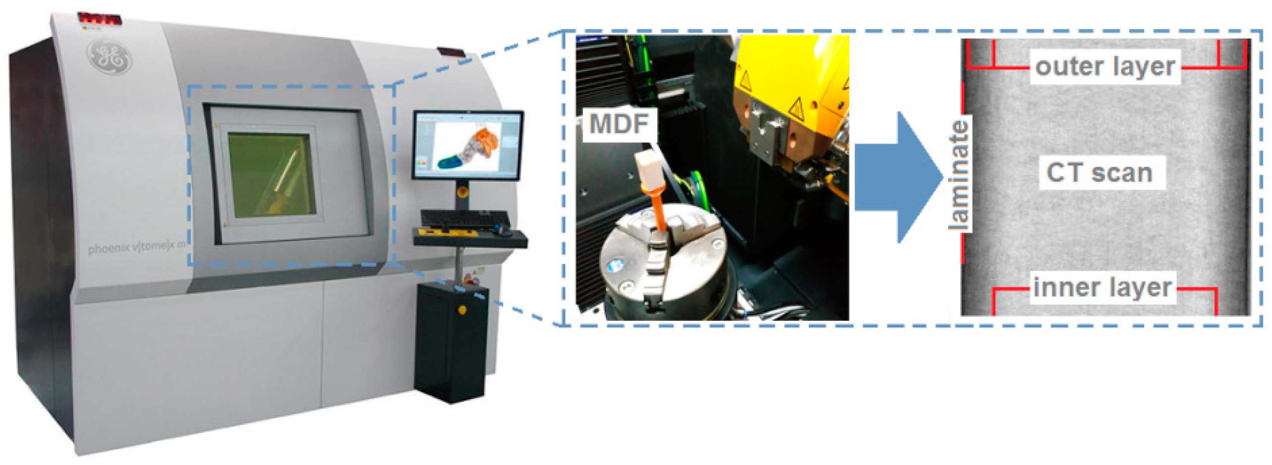
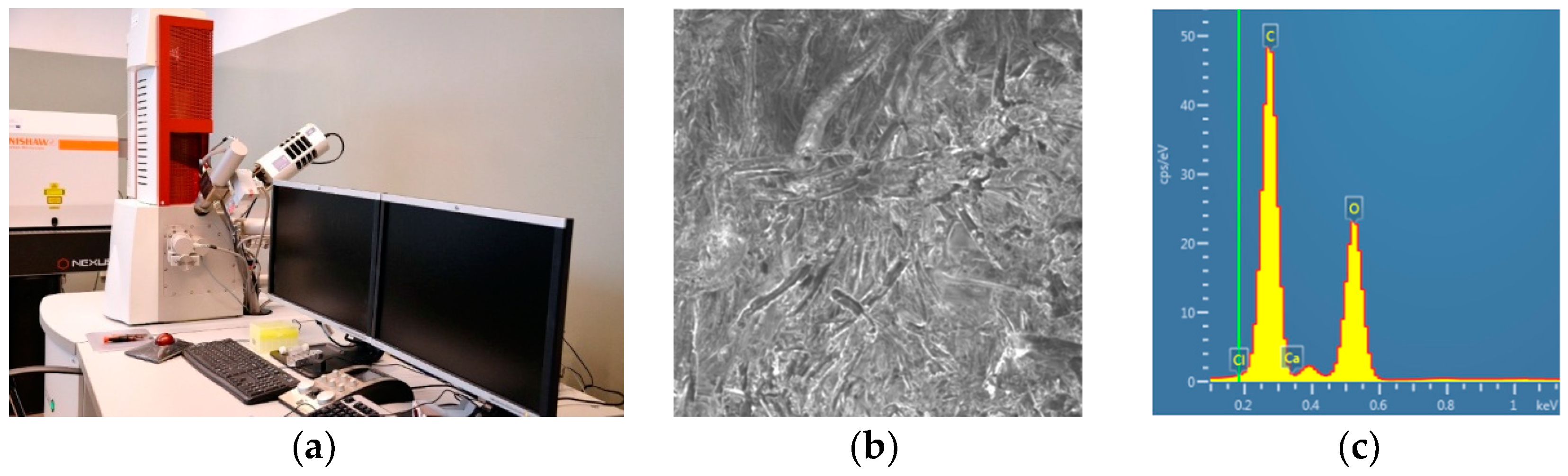
2.1. Material
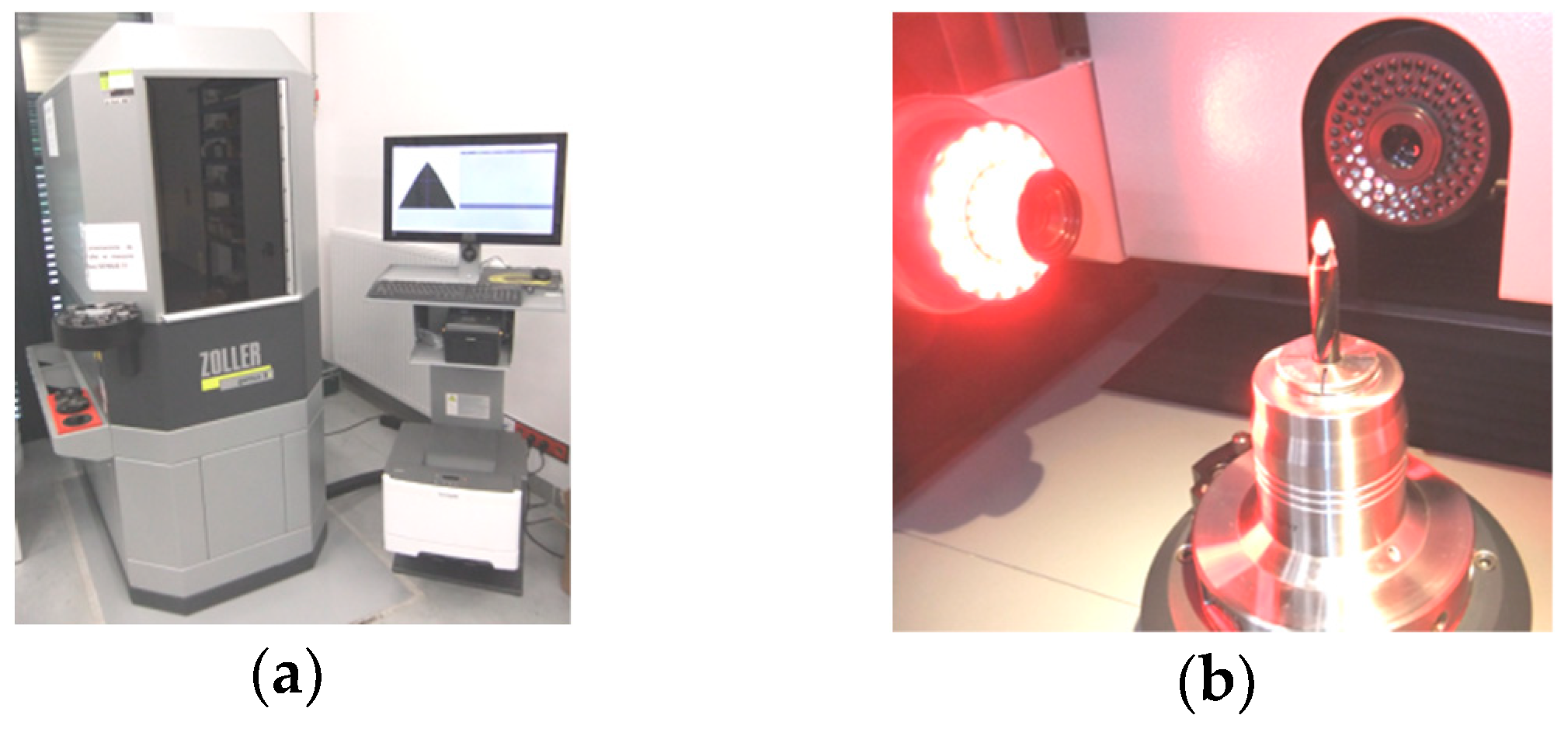
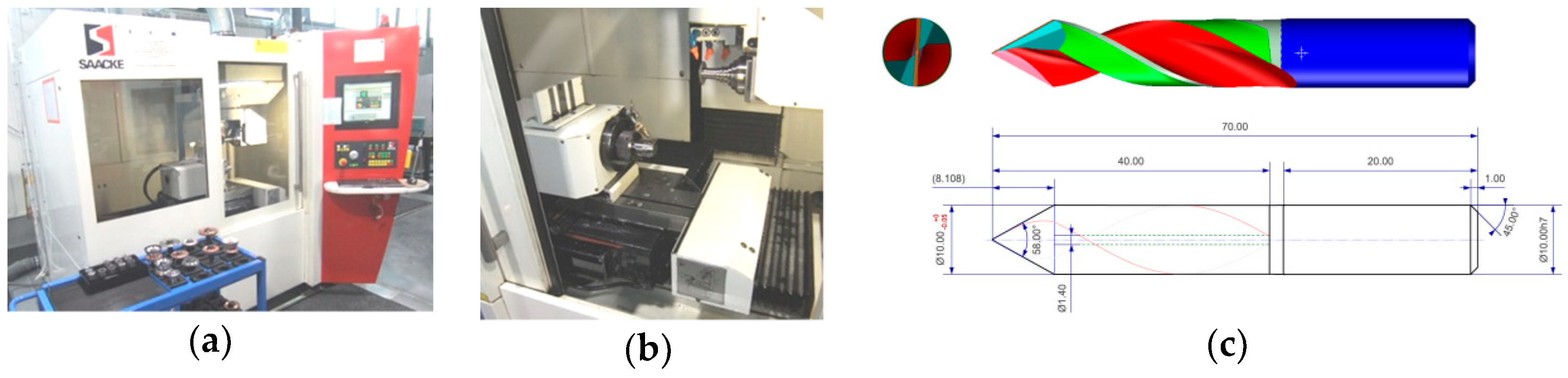
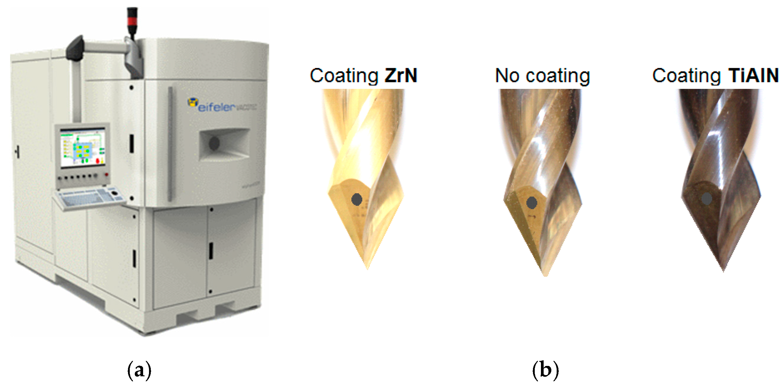
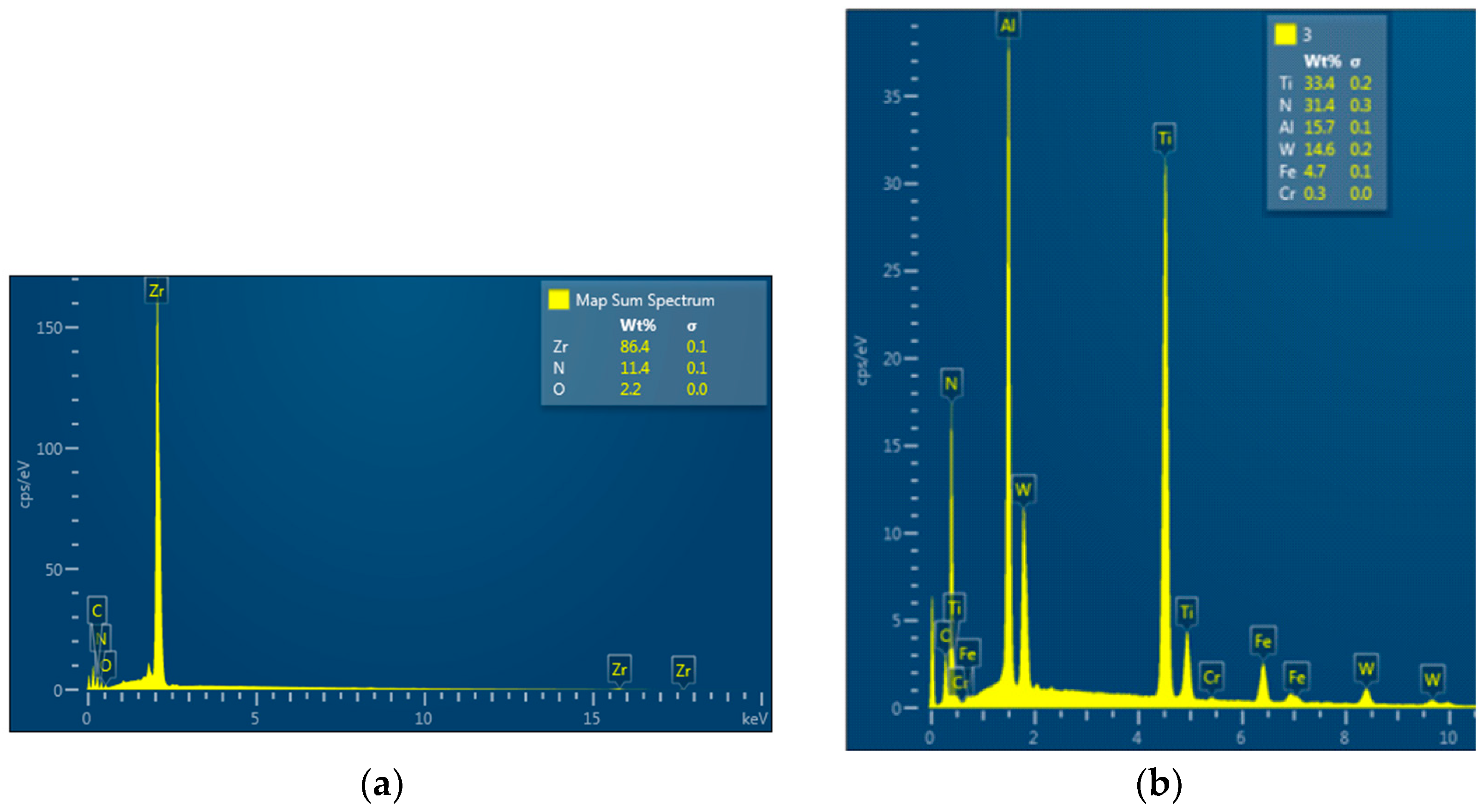
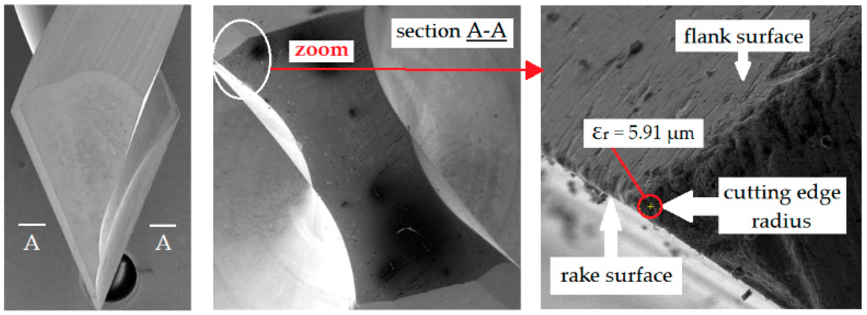
2.2. Cutting Tools
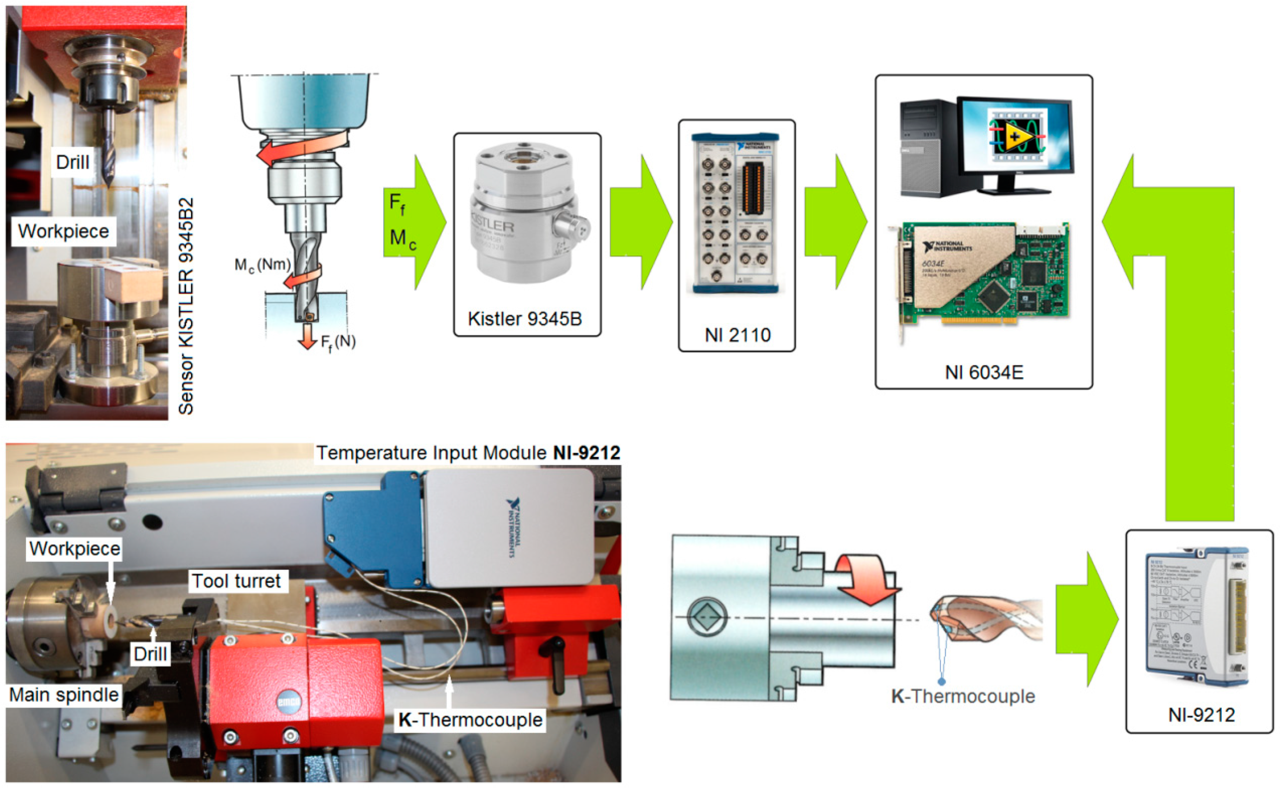
2.3. Equipment and Machining Conditions
3. Results
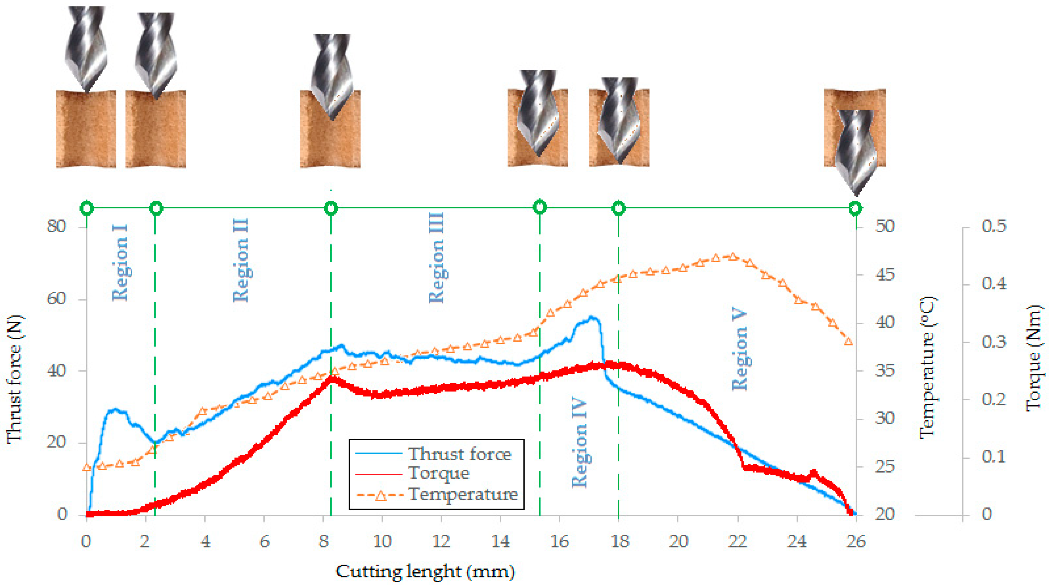
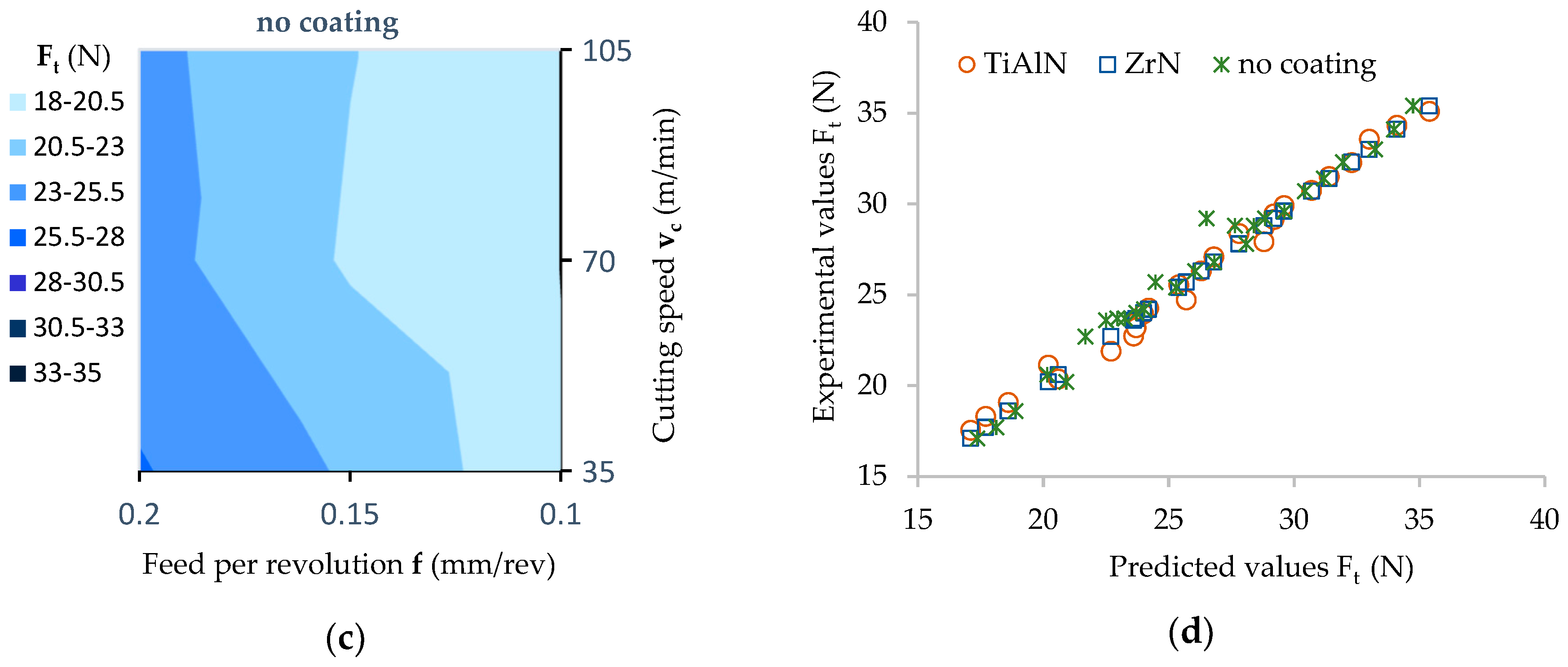
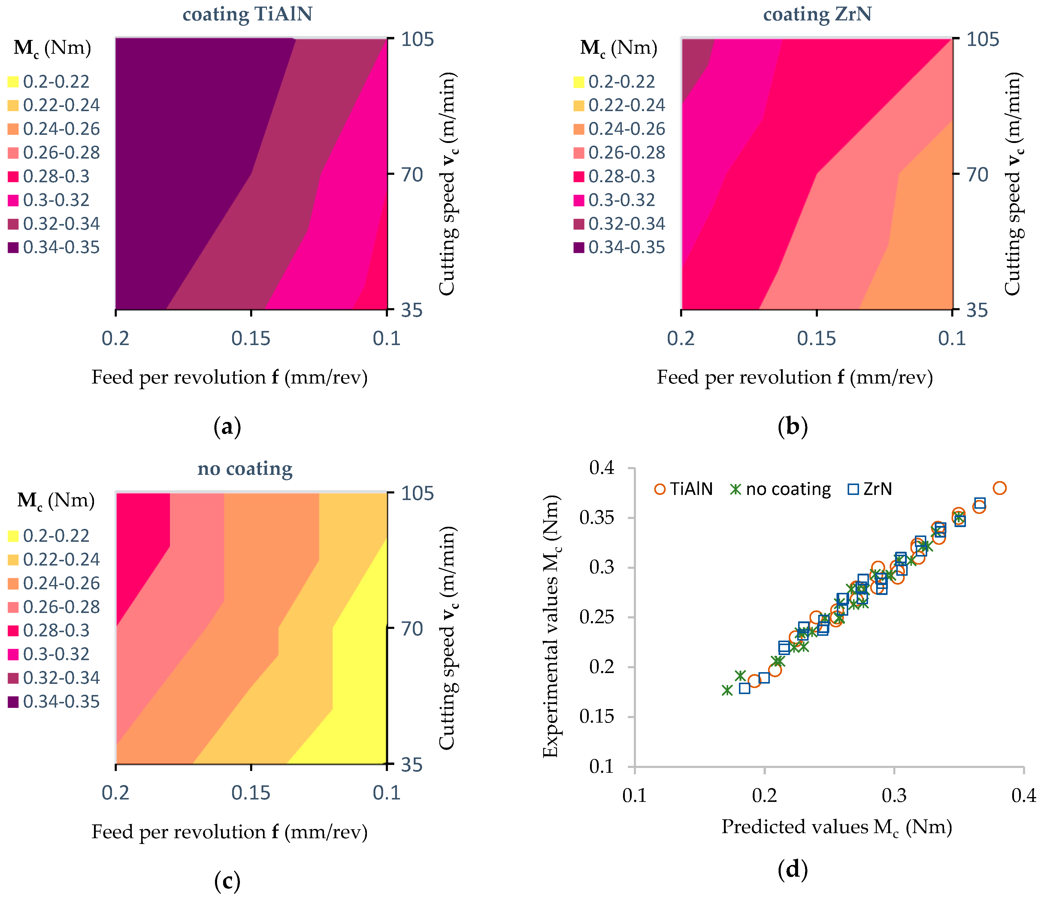
3.1. Feed Force and Cutting Torque
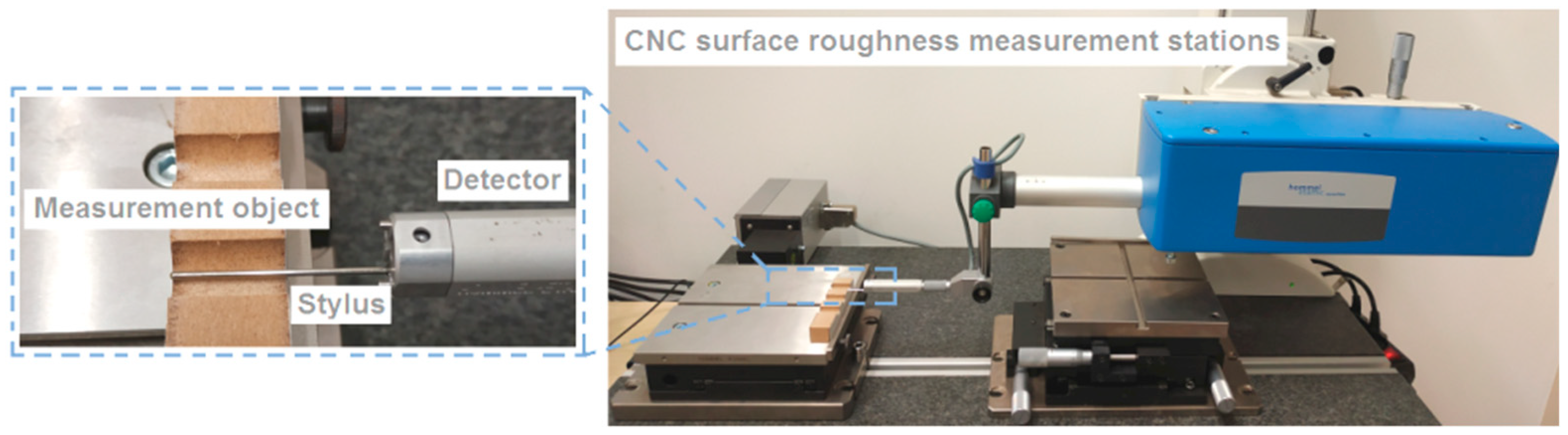
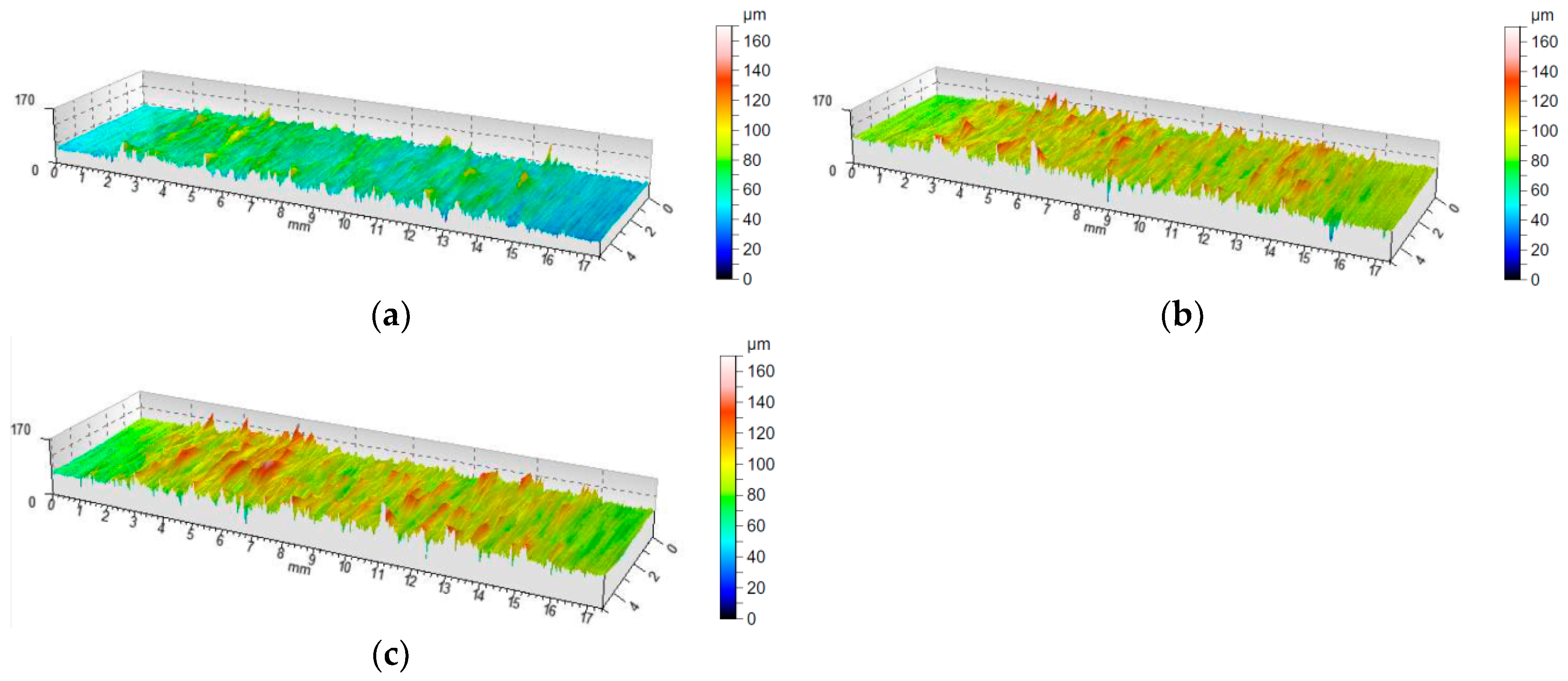
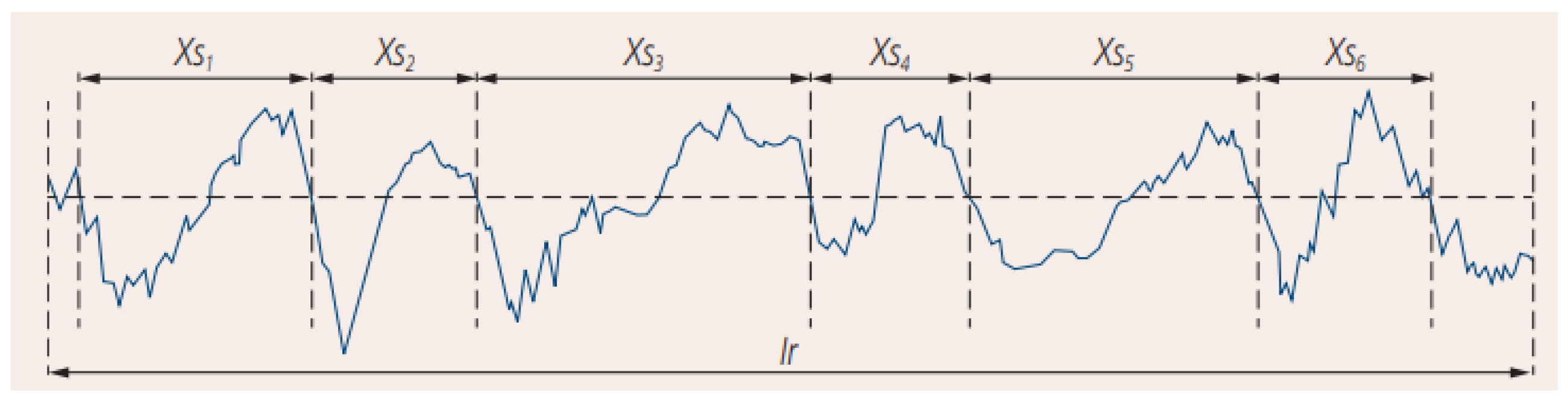
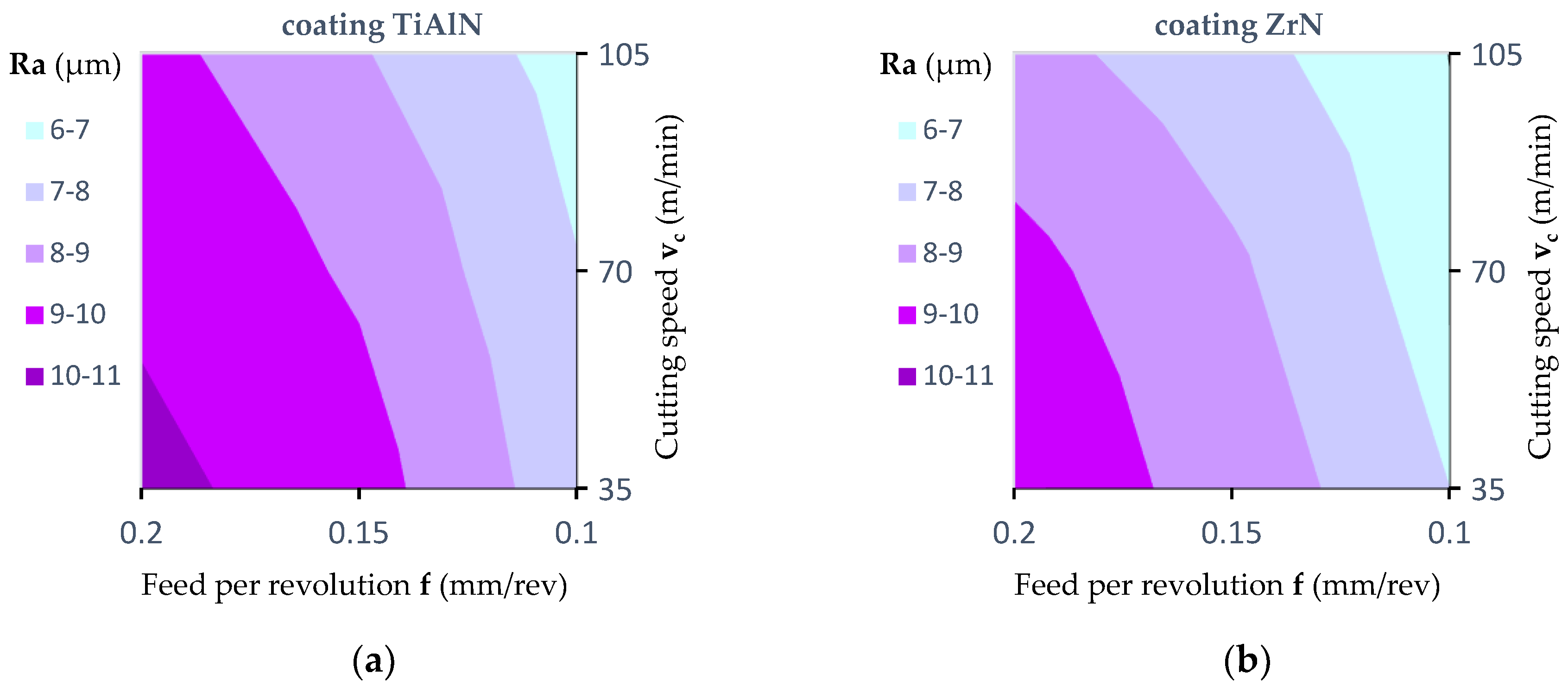
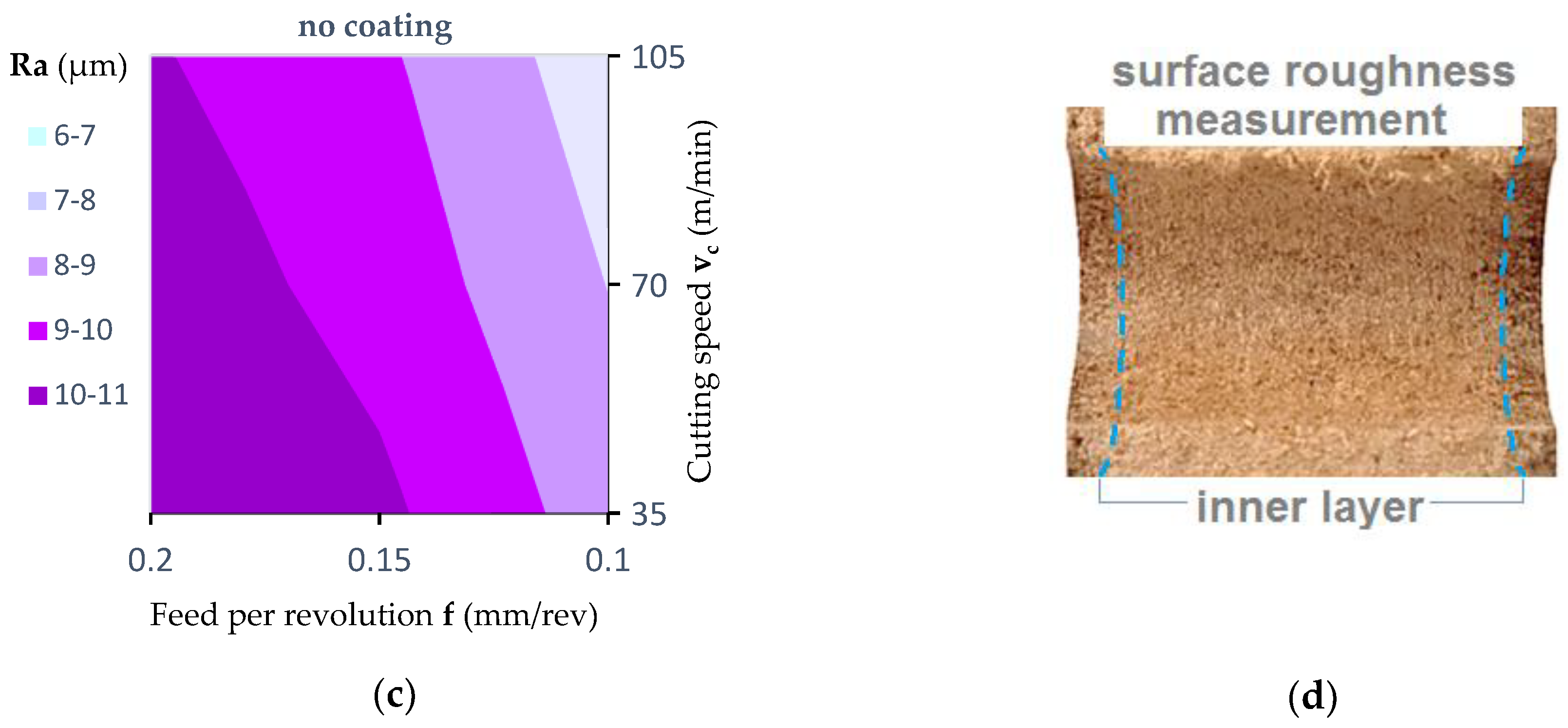
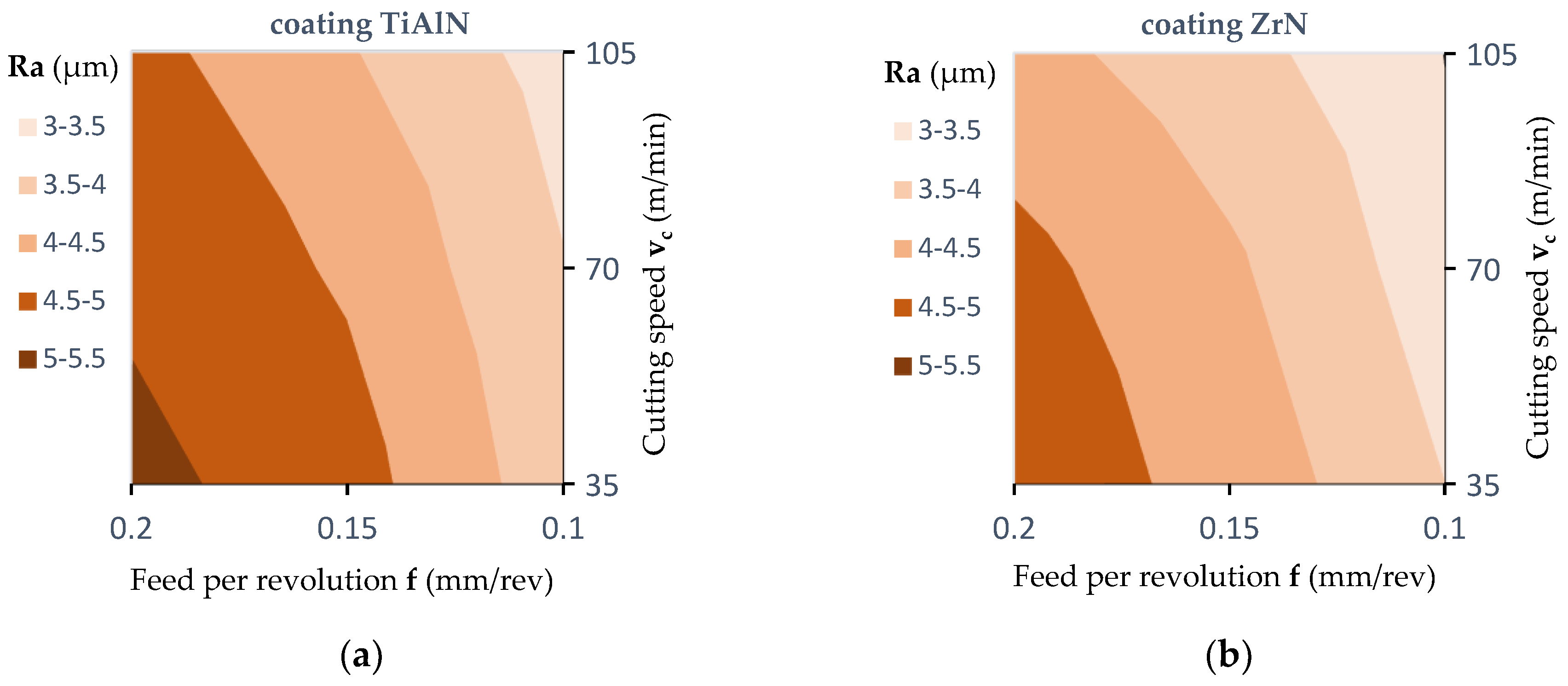
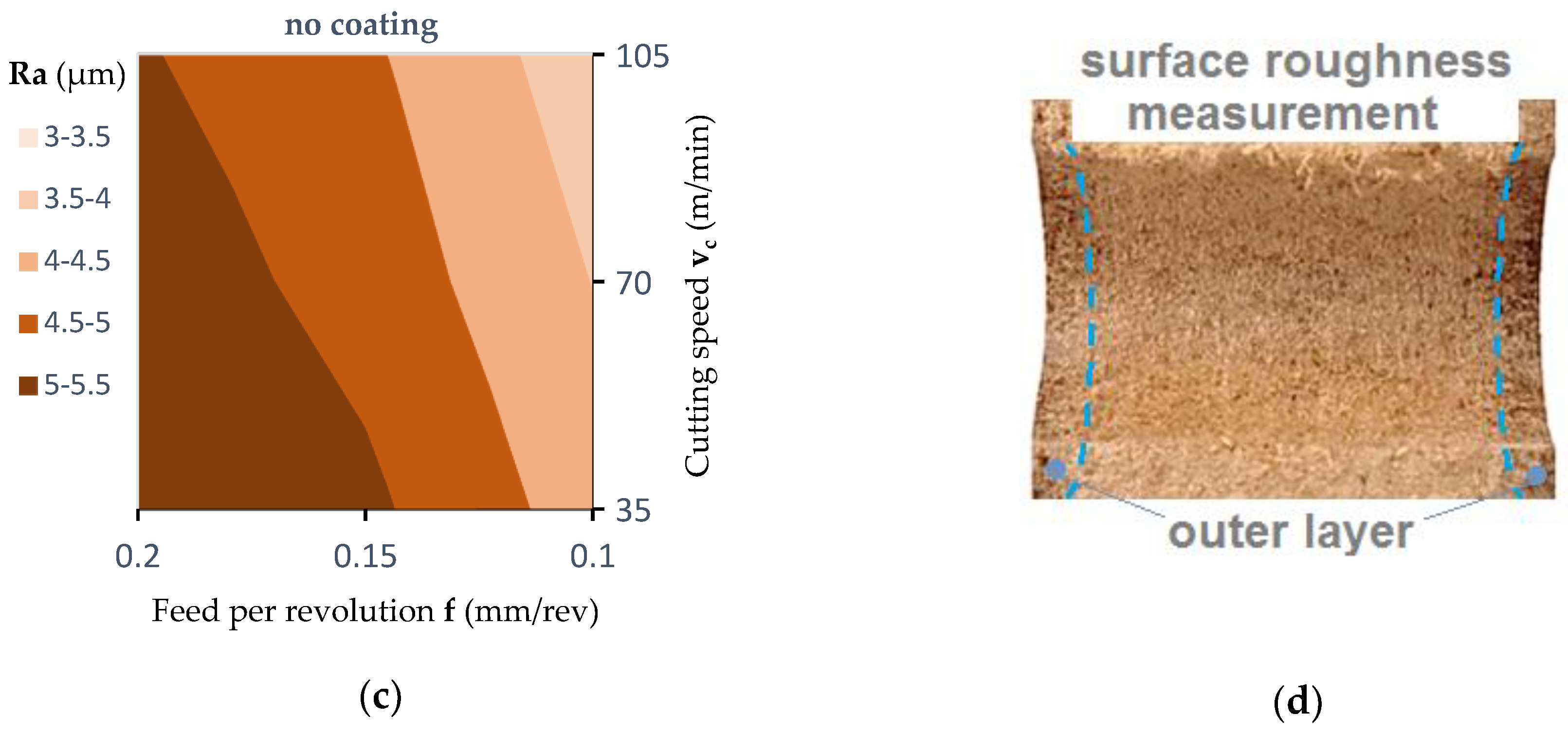
3.2. Analysis of Surface Topography
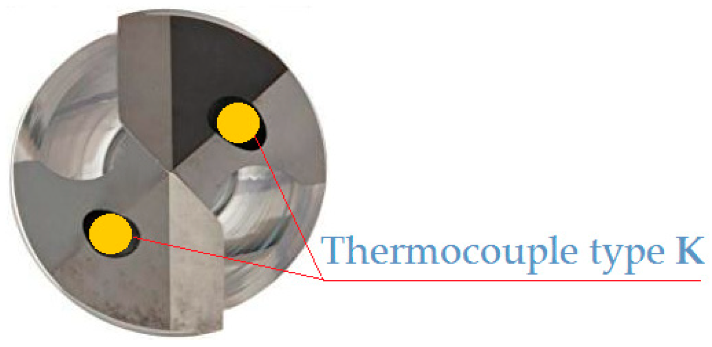
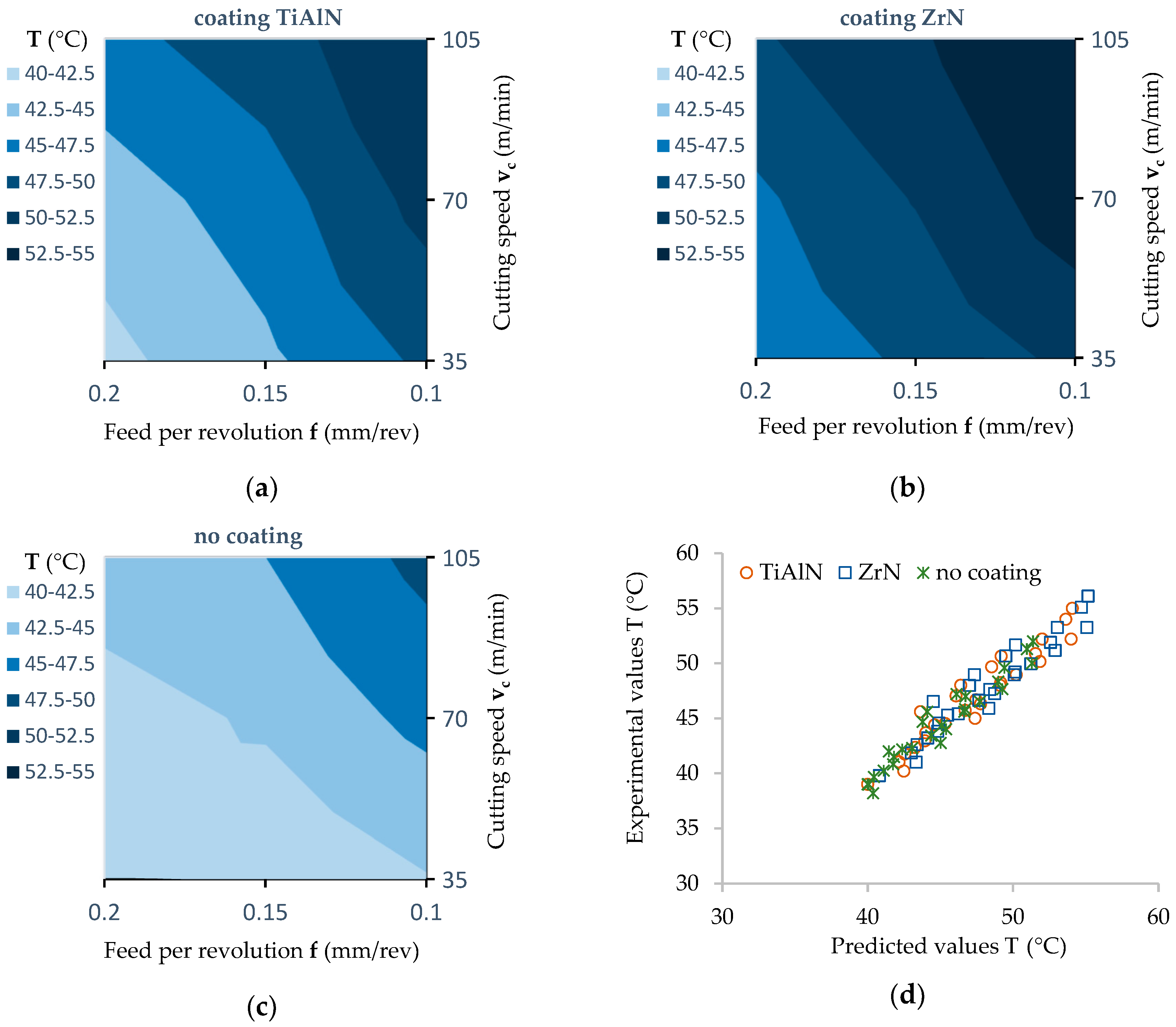
3.3. Temperature of Cutting Tools
4. Conclusions
- In the analysis of the values of thrust force (Ft), cutting torque (Mc), and surface roughness parameter (Ra) the layered structure of the MDF panel, which consists of layers of different density and hardness, should be taken into account.
- A significant effect of the type of drill coating on the value of all the MDF machinability indices analyzed was observed.
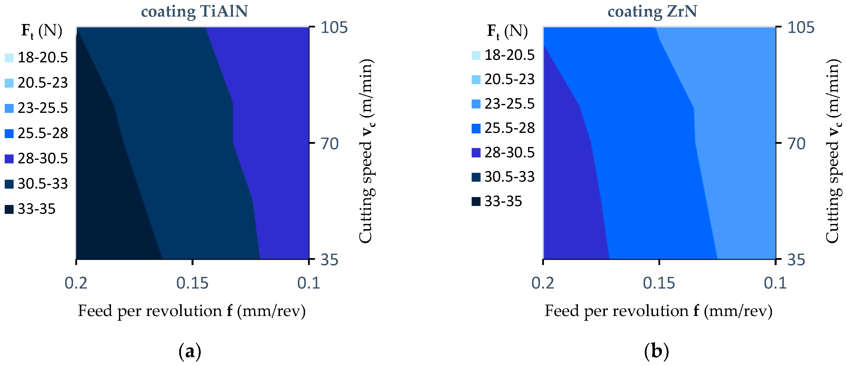
- There is a dominant influence of both the feed per revolution (f) and the type of tool coating on thrust force (Ft), cutting torque (Mc) and cutting tool temperature in the MDF drilling process. The highest values of cutting torque (Mc) and thrust force (Ft) recorded in the experiments were obtained using a drill with a TiAlN coating. In contrast, the lowest values of Mc and Ft were obtained using an uncoated drill. This fact can be explained by the differing values of the coefficient of friction between the tool and the workpiece resulting from the type of drill coating. The coated drill surfaces are characterized by the relatively higher friction coefficients than the surface of uncoated ceented carbide tool. Therefore, the coating increases the friction force between the tool and the workpiece, according to the Marchant’s Circle diagram. Increasing in the friction force causes an increase of the cutting resistance.
- The test results obtained show that the temperature in the drilling process increases with increase in cutting speed (vc) but decreases with an increase of the feed per revolution (f) value. Temperature changes, depending on the coating type, vary on average by approximately 20%. The highest values of tool temperature were observed in the case of the ZrN coated drill, and the lowest in the case of the uncoated drill. This fact can be explained as follows: the ZrN coating has a much lower heat transfer coefficient compared to the TiAlN coating and uncoated tool. This causes the ZrN coating to be a barrier to removing heat from the cutting zone.
- The feed per revolution (f) and the type of drill coating had a significant influence on the value of the roughness average (Ra) parameter. It has been observed that in the outer layers of the panel, the (Ra) parameter value has a lower value compared to that measured in the middle layer. The lowest value of roughness average parameter (Ra) was observed in the case of the ZrN coated drill, and the highest in the case of the uncoated drill. This fact can be explained by a lower value of friction coefficient and a lower value of thermal conductivity coefficient of ZrN coating compared to the uncoated tool. The lower value both of thermal conductivity coefficient and friction coefficient causes an increase in heat generated in the area of contact between the cutting tool and the workpiece. In the case of MDF, this significantly improves the connection of wood fibers and formaldehyde adhesive. It causes the compaction of the bonds between fibers.
Author Contributions
Funding
Acknowledgments
Conflicts of Interest
References
- Clarke, P.A. Panel products—Past, present and future—Developments 1991. J. Inst. Wood Sci. 1991, 12, 233–241. [Google Scholar]
- Davim, J.P.; Clemente, V.C.; Silva, S. Surface roughness aspects in milling MDF (medium density fibreboard). Int. J. Adv. Manuf. Technol. 2009, 40, 49–55. [Google Scholar] [CrossRef]
- Davim, P.; Rubio, C.; Abrao, M. Delamination assessment after drilling medium-density fibreboard (MDF) by digital image analysis. Holzforschung 2007, 61, 294–300. [Google Scholar] [CrossRef]
- Engin, S.; Altintas, Y.; Amara, F.B. Mechanics of routing medium density fibreboard. For. Prod. J. 2000, 50, 65–69. [Google Scholar]
- Szwajka, K.; Trzepiecinski, T. On the machinability of medium density fiberboard by drilling. BioResources 2018, 13, 8263–8278. [Google Scholar] [CrossRef]
- Penman, D.; Olsson, O.J.; Bowman, C.C. Automatic inspection of reconstituted wood panels for surface defects. In Machine Vision Applications, Architectures, and Systems Integration; International Society for Optics and Photonics: Bellingham, WA, USA, 1993; Volume 1823, pp. 284–293. [Google Scholar]
- Bhattacharyya, D.; Allen, M.N.; Mander, S.J. Cryogenic machining of Kevlar composites. Mater. Manuf. Process 1993, 8, 631–652. [Google Scholar] [CrossRef]
- Costes, J.; Larricq, P. Towards high cutting speed in wood milling. Ann. For. Sci. 2002, 59, 857–865. [Google Scholar] [CrossRef]
- Dippon, J.; Ren, H.; Amara, F.B.; Altintas, Y. Orthogonal cutting mechanics of medium density fibreboards. For. Prod. J. 2000, 50, 25–30. [Google Scholar]
- Gordon, S.; Hillery, M.T. A review of the cutting of composite materials. Proc. Inst. Mech. Eng. Part L J. Mater. Des. Appl. 2003, 217, 35–45. [Google Scholar] [CrossRef]
- Nouari, M.; Makich, H. On the physics of machining titanium alloys: Interactions between cutting parameters, microstructure and tool wear. Metals 2014, 4, 335–358. [Google Scholar] [CrossRef]
- Haddag, B. Metals machining—Recent advances in experimental and modeling of the cutting process. Metals 2018, 8, 1053. [Google Scholar] [CrossRef]
- Wyeth, D.; Goli, G.; Atkins, A. Fracture toughness, chip types and the mechanics of cutting wood. Holzforschung 2009, 63, 168–180. [Google Scholar] [CrossRef]
- Marchal, R.; Mothe, F.; Denaud, L.; Thibaut, B.; Bleron, L. Cutting forces in wood machining—Basics and applications in industrial processes. Holzforschung 2009, 63, 157–167. [Google Scholar] [CrossRef]
- Szwajka, K.; Trzepiecinski, T. An examination of the tool life and surface quality during drilling melamine faced chipboard. Wood Res. 2017, 62, 307–318. [Google Scholar]
- Djouadi, A.; Beer, P.; Marchal, R.; Sokolowska, A.; Lambertin, M.; Precht, W.; Nouveau, C. Antiabrasive coatings: Application for wood processing. Surf. Coat. Technol. 1999, 116–119, 508–516. [Google Scholar] [CrossRef]
- Djouadi, A.; Nouveau, C.; Beer, P.; Lambertin, M. CrxNy hard coatings deposited with PVD method on tools for wood machining. Sur. Coat. Technol. 2000, 133–134, 478–483. [Google Scholar] [CrossRef]
- Faga, M.G.; Settineri, L. Innovative anti-wear coatings on cutting tools for wood machining. Surf. Coat. Technol. 2006, 201, 3002–3007. [Google Scholar] [CrossRef]
- Nouveau, C.; Djouadi, A.; Marchal, R.; Lambertin, M. Application of CrAlN coatings on carbide substrates in routing of MDF. Wear 2007, 263, 1291–1299. [Google Scholar] [CrossRef]
- Nouveau, C.; Jorand, E.; Deces-Petit, C.; Labidi, C.; Djouadi, A. Influence of carbide substrates on tribological properties of chromium and chromium nitride coatings: Application to wood machining. Wear 2005, 258, 157–165. [Google Scholar] [CrossRef]
- Pinheiro, D.; Vieira, M.T.; Djouadi, A. Avantages of depositing multilayer coatings for cutting wood-based products. Surf. Coat. Technol. 2009, 203, 3197–3205. [Google Scholar] [CrossRef]
- Szwajka, K.; Trzepiecinski, T. Effect of tool material on tool wear and delamination during machining of particleboard. J. Wood Sci. 2016, 62, 305–315. [Google Scholar] [CrossRef]
- Sedlecký, M. Surface roughness of medium-density fiberboard (MDF) and edge-glued panel (EGP) after edge milling. BioResources 2017, 12, 8119–8133. [Google Scholar] [CrossRef]
- Tiryaki, S.; Hamzaçebi, C.; Malkoçoğlu, A. Evaluation of process parameters for lower surface roughness in wood machining by using Taguchi design methodology. Eur. J. Wood Wood Prod. 2015, 73, 537–545. [Google Scholar] [CrossRef]
- Boucher, J.; Méausoone, P.-J.; Martin, P.; Auchet, S.; Perrin, L. Influence of helix angle and density variation on the cutting force in wood-based products machining. J. Mater. Process. Technol. 2007, 189, 211–218. [Google Scholar] [CrossRef]
- Gurau, L.; Mansfield-Williams, H.; Irle, M. Processing roughness of sanded wood surfaces. Holz als Roh und Werkstoff 2005, 63, 43–52. [Google Scholar] [CrossRef]
- Thoma, H.; Peri, L.; Lato, E. Evaluation of wood surface roughness depending on species characteristics. Maderas Ciencia y Tecnología 2015, 17, 285–292. [Google Scholar] [CrossRef]
- Akgül, M.; Korkut, S.; Çamlibel, O.; Candan, Z.; Akbulut, T. Wettability and surface roughness characteristics of medium density fiberboard panels from rhododendron (Rhododendron ponticum) biomass. Maderas Ciencia y Tecnología 2012, 14, 185–193. [Google Scholar] [CrossRef]
- Novák, V.; Rousek, M.; Kopecký, Z. Assessment of wood surface quality obtained during high speed milling by use of non-contact method. Drvna Industrija 2011, 62, 103–115. [Google Scholar] [CrossRef]
- Taylor, J.B.; Carrano, A.L.; Lemaster, R.L. Quantification of process parameters in a wood sanding operation. For. Prod. J. 1999, 49, 41–46. [Google Scholar]
- Barcík, Š.; Gašparík, M. Effect of tool and milling parameters on the size distribution of splinters of planed native and thermally modified beech wood. BioResources 2014, 9, 1346–1360. [Google Scholar] [CrossRef]
- Gaitonde, N.; Karnik, R.; Davim, P. Taguchi multiple-performance characteristics optimization in drilling of medium density fiberboard (MDF) to minimize delamination using utility concept. J. Mater. Process. Technol. 2008, 196, 73–78. [Google Scholar] [CrossRef]
- Škaljić, N.; Beljo-Lučić, R.; Čavlović, A.; Obućina, M. Effect of feed rate and wood species on roughness of machined surface. Drvna Industrija 2009, 60, 229–234. [Google Scholar] [CrossRef]
- Szwajka, K.; Trzepiecinski, T. The influence of machining parameters and tool wear on the delamination process during milling of melamine-faced chipboard. Drewno 2017, 60, 117–131. [Google Scholar] [CrossRef]
- Kvietková, M.; Gašparík, M.; Gaff, M. Effect of thermal treatment on surface quality of beech wood after plane milling. BioResources 2015, 10, 4226–4238. [Google Scholar] [CrossRef]
- Lin, R.J.T.; van Houts, J.; Bhattacharyya, D. Machinability investigation of medium-density fibreboard. Holzforschung 2006, 60, 71–77. [Google Scholar] [CrossRef]
- Sütçü, A. Investigation of parameters affecting surface roughness in CNC routing operation on wooden EGP. BioResources 2013, 8, 795–805. [Google Scholar] [CrossRef]
- Davim, J.P.; Reis, P.; Antonio, C.C. Experimental study of drilling glass fiber reinforced plastics (GFRP) manufactured by hand lay-up. Compos. Sci. Technol. 2004, 64, 289–297. [Google Scholar] [CrossRef]
- Candan, Z.; Büyüksarı, U.; Korkut, S.; Unsal, O.; Çakıcıer, N. Wettability and surface roughness of thermally modified plywood panels. Ind. Crop. Prod. 2012, 36, 434–436. [Google Scholar] [CrossRef]
- Liu, D.; Tang, Y.; Cong, W. A review of mechanical drilling for composite laminates. Compos. Struct. 2012, 94, 1265–1279. [Google Scholar] [CrossRef]


| Density (kg/m3) | Moisture Content (%) | Bending Strength (MPa) | Elasticity Modulus (MPa) | Thermal Conductivity (W/(m·K)) | Thermal Expansion (µm/(m·K)) |
|---|---|---|---|---|---|
| 742 | 7.2 | 38 | 2530 | 0.3 | 12 |
| Type of coating | Coating Temperature (°C) | Hardness (HV) | Thickness (µm) | Coefficient of Friction | Thermal Conductivity (W/(m·K)) |
|---|---|---|---|---|---|
| ZrN | 350–500 | 2200 | 2–3 | 0.4 | 0.28 |
| TiAlN | 400–500 | 3000 | 2–3 | 0.6 | 2.48 |
| Cutting Speed (m/min) | Feed Per Revolution (mm/rev) | Feed Rate (mm/min) | Rotational Speed of Drill (rev/min) |
|---|---|---|---|
| 35 | 0.10 | 111 | 1114 |
| 35 | 0.15 | 167 | 1114 |
| 35 | 0.20 | 222 | 1114 |
| 70 | 0.10 | 222 | 2229 |
| 70 | 0.15 | 334 | 2229 |
| 70 | 0.20 | 445 | 2229 |
| 105 | 0.10 | 334 | 3344 |
| 105 | 0.15 | 501 | 3344 |
| 105 | 0.20 | 668 | 3344 |
| Tests Applied | Level of Significance (p ≤ 0.05) |
|---|---|
| cutting speed (vc) | 0.000 |
| feed per revolution (f) | 0.000 |
| coating | 0.000 |
| coating × cutting speed | 0.997 |
| coating × feed per revolution | 0.564 |
| Tests Applied | Level of Significance (p ≤ 0.05) |
|---|---|
| cutting speed (vc) | 0.000 |
| feed per revolution (f) | 0.000 |
| coating | 0.000 |
| coating × cutting speed | 0.853 |
| coating × feed per revolution | 0.734 |
| Mean Groove Spacing for Periodic Profiles RSm (mm) | Measurement Parameter | |||
|---|---|---|---|---|
| λc = lc (mm) | ln (mm) | lt (mm) | rtip (μm) | |
| 0.013 < RSm ≤ 0.04 | 0.08 | 0.4 | 0.48 | 2 |
| 0.04 < RSm ≤ 0.13 | 0.25 | 1.25 | 1.5 | 2 |
| 0.13 < RSm ≤ 0.4 | 0.8 | 4 | 4.8 | 2 or 5 |
| 0.4 < RSm ≤ 1.3 | 2.5 | 12.5 | 15 | 5 |
| 1.3 < RSm ≤ 4 | 8 | 40 | 48 | 10 |
| Tests Applied | Level of Significance (p ≤ 0.05) |
|---|---|
| cutting speed (vc) | 0.252 |
| feed per revolution (f) | 0.000 |
| coating | 0.000 |
| coating × cutting speed | 0.999 |
| coating × feed per revolution | 0.998 |
| Tests Applied | Level of Significance (p ≤ 0.05) |
|---|---|
| cutting speed (vc) | 0.006 |
| feed per revolution (f) | 0.000 |
| coating | 0.000 |
| coating × cutting speed | 0.998 |
| coating × feed per revolution | 0.943 |
© 2019 by the authors. Licensee MDPI, Basel, Switzerland. This article is an open access article distributed under the terms and conditions of the Creative Commons Attribution (CC BY) license (http://creativecommons.org/licenses/by/4.0/).
Share and Cite
Szwajka, K.; Zielińska-Szwajka, J.; Trzepiecinski, T. Experimental Study on Drilling MDF with Tools Coated with TiAlN and ZrN. Materials 2019, 12, 386. https://doi.org/10.3390/ma12030386
Szwajka K, Zielińska-Szwajka J, Trzepiecinski T. Experimental Study on Drilling MDF with Tools Coated with TiAlN and ZrN. Materials. 2019; 12(3):386. https://doi.org/10.3390/ma12030386
Chicago/Turabian StyleSzwajka, Krzysztof, Joanna Zielińska-Szwajka, and Tomasz Trzepiecinski. 2019. "Experimental Study on Drilling MDF with Tools Coated with TiAlN and ZrN" Materials 12, no. 3: 386. https://doi.org/10.3390/ma12030386
APA StyleSzwajka, K., Zielińska-Szwajka, J., & Trzepiecinski, T. (2019). Experimental Study on Drilling MDF with Tools Coated with TiAlN and ZrN. Materials, 12(3), 386. https://doi.org/10.3390/ma12030386