Fabrication, Corrosion, and Mechanical Properties of Magnetron Sputtered Cu–Zr–Al Metallic Glass Thin Film


Abstract
1. Introduction
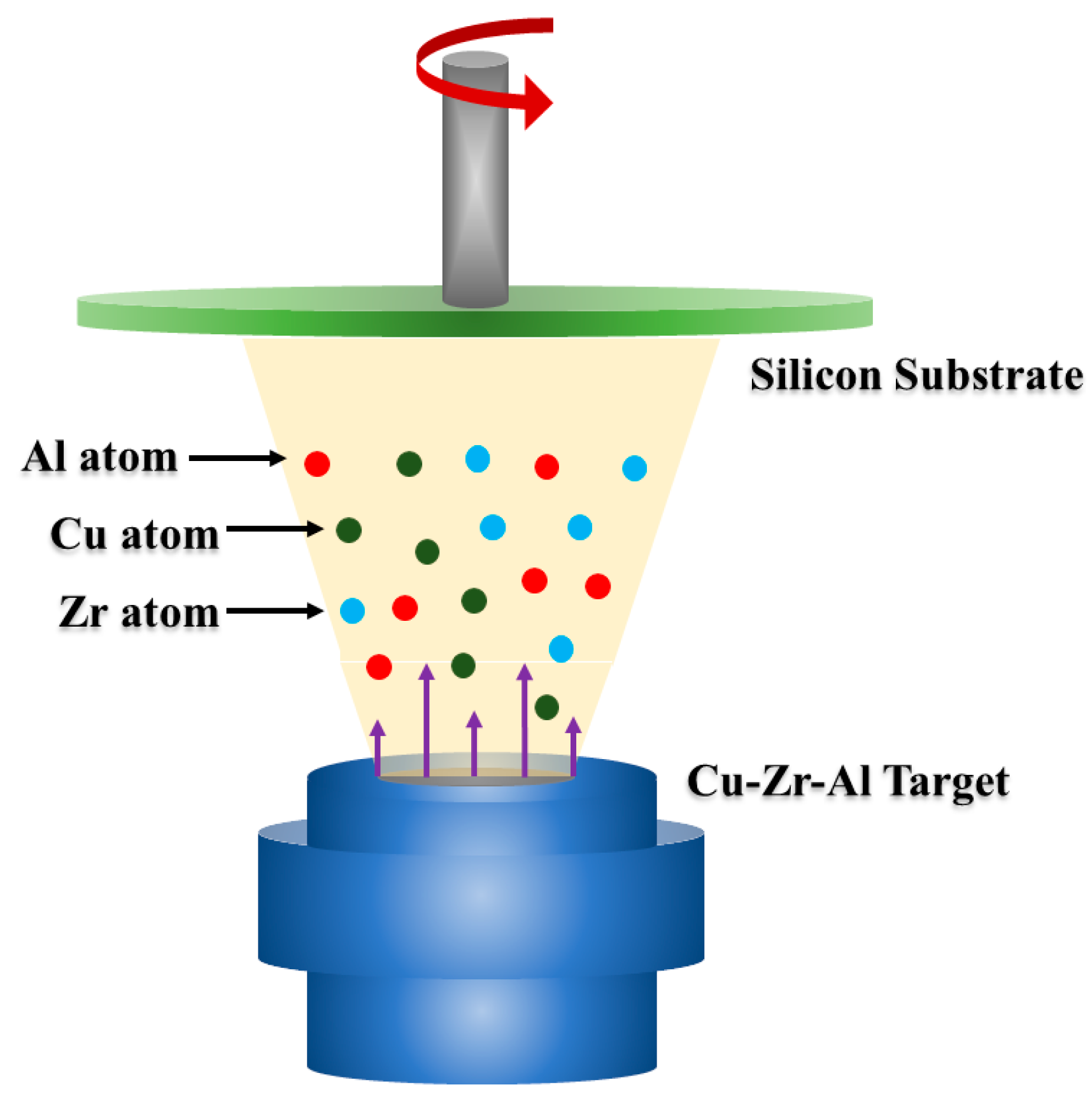
2. Experimental
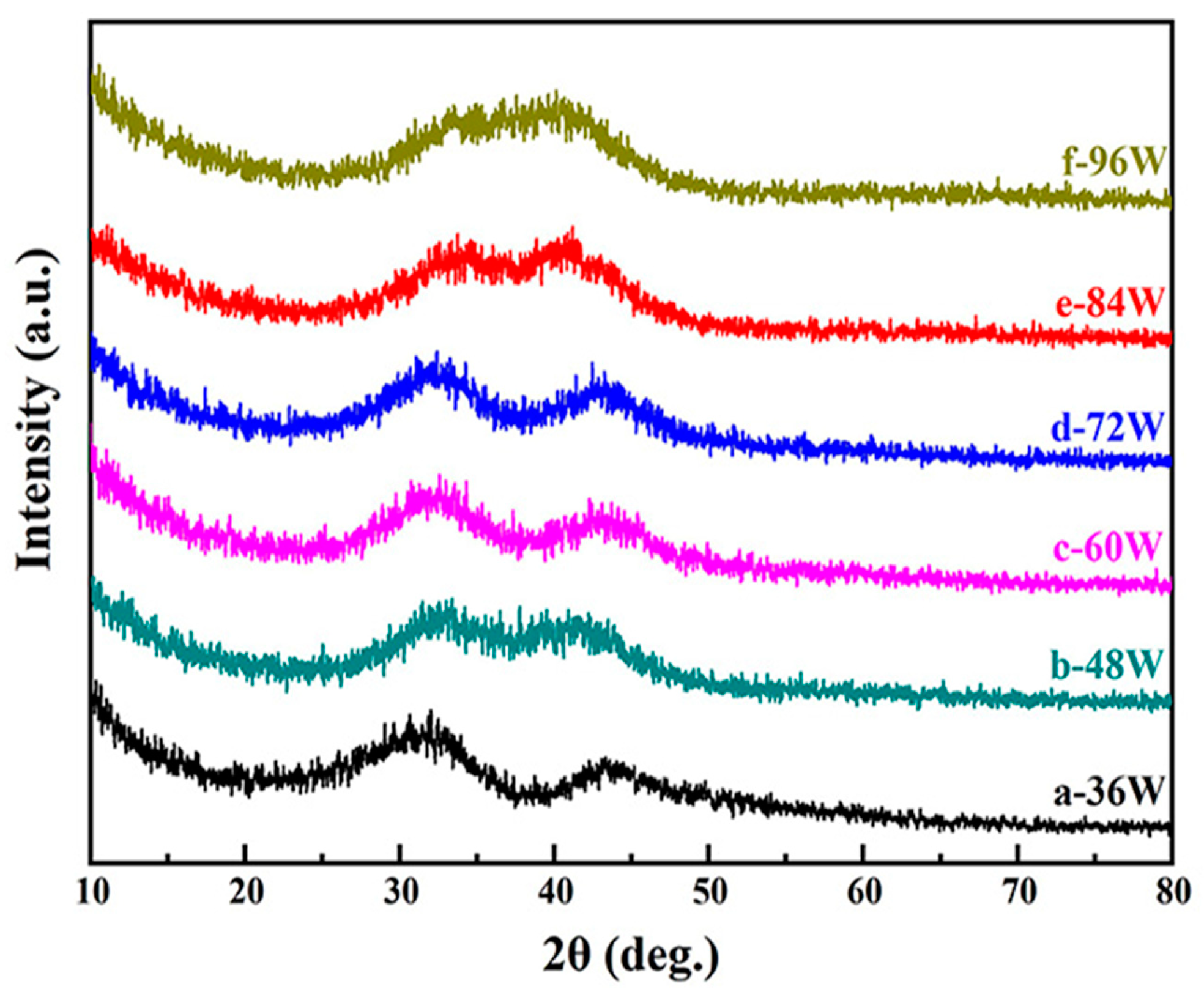
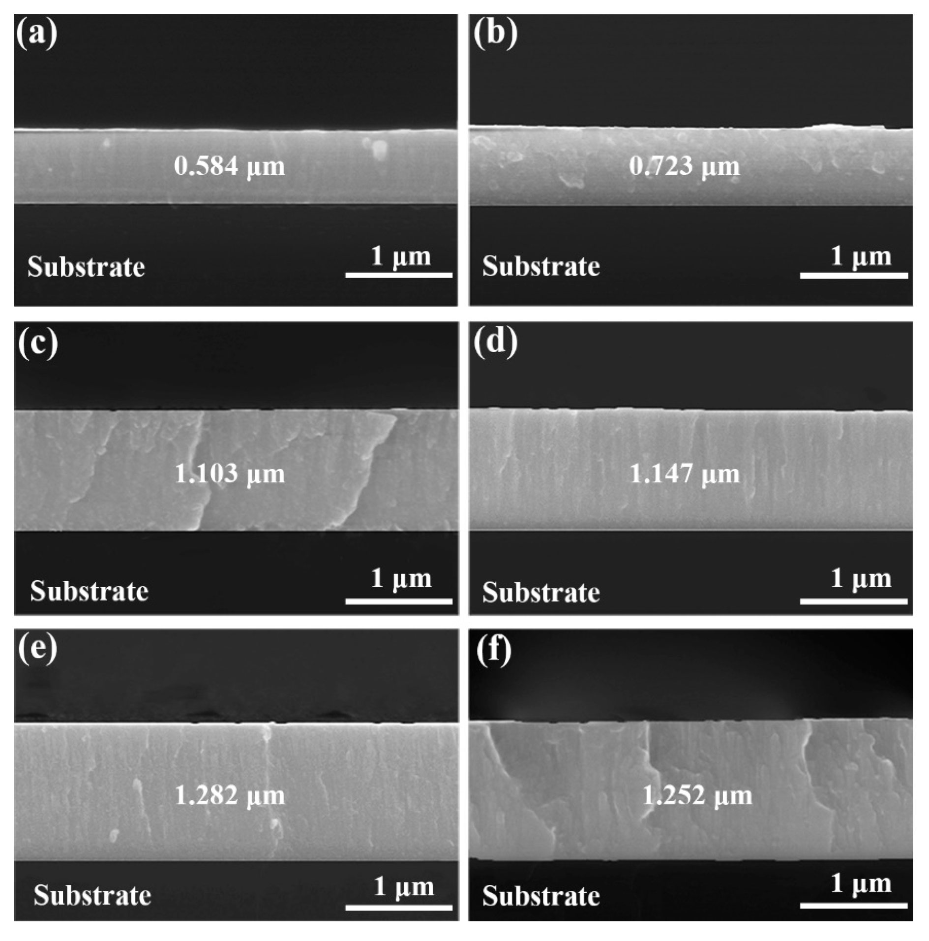
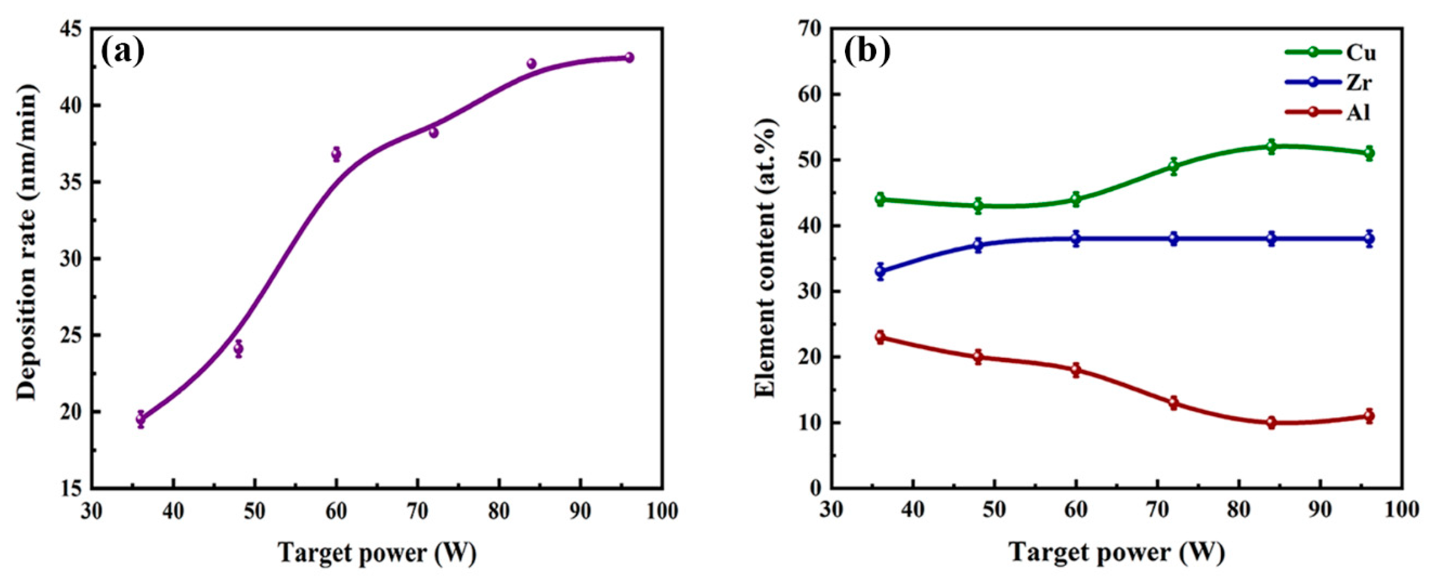
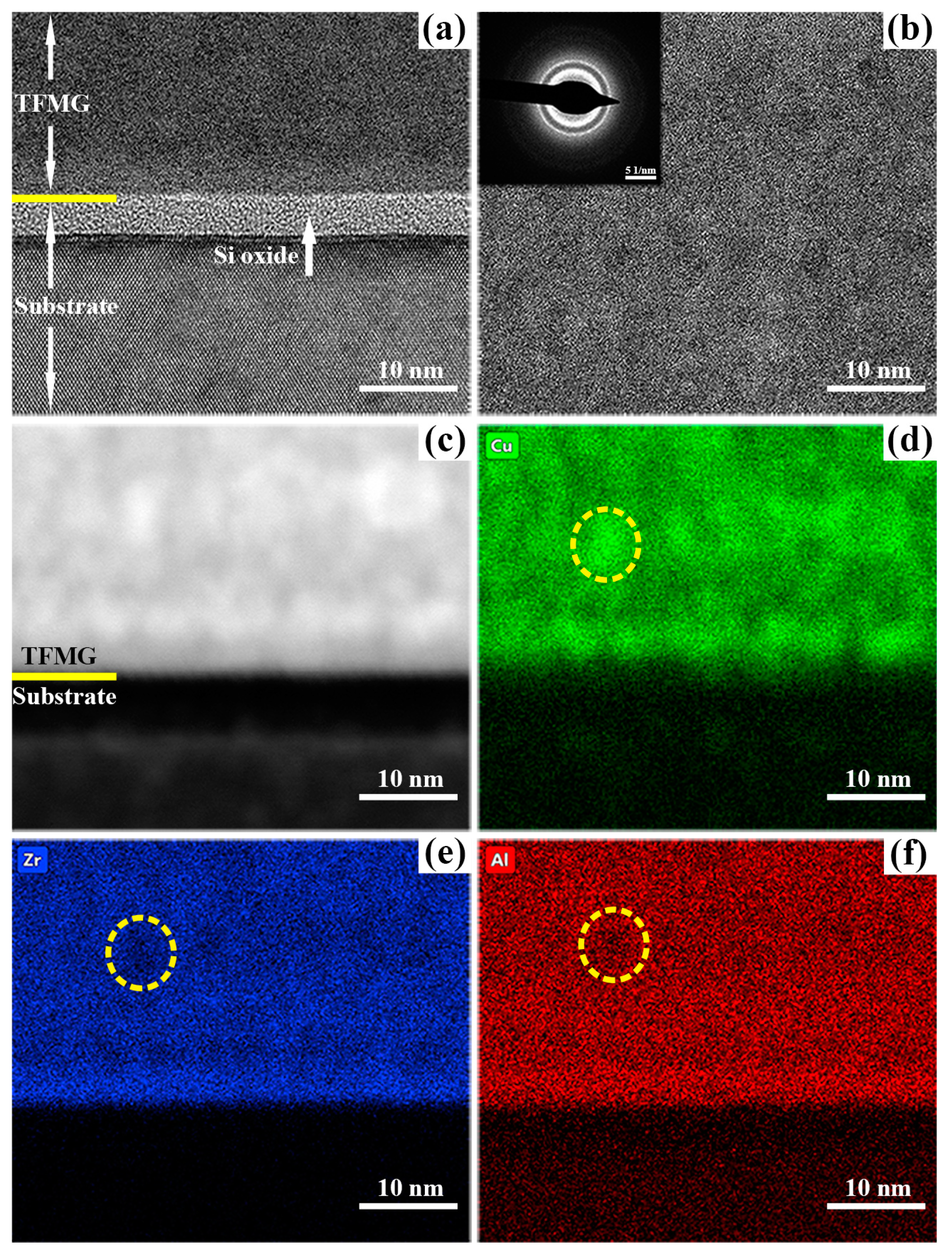
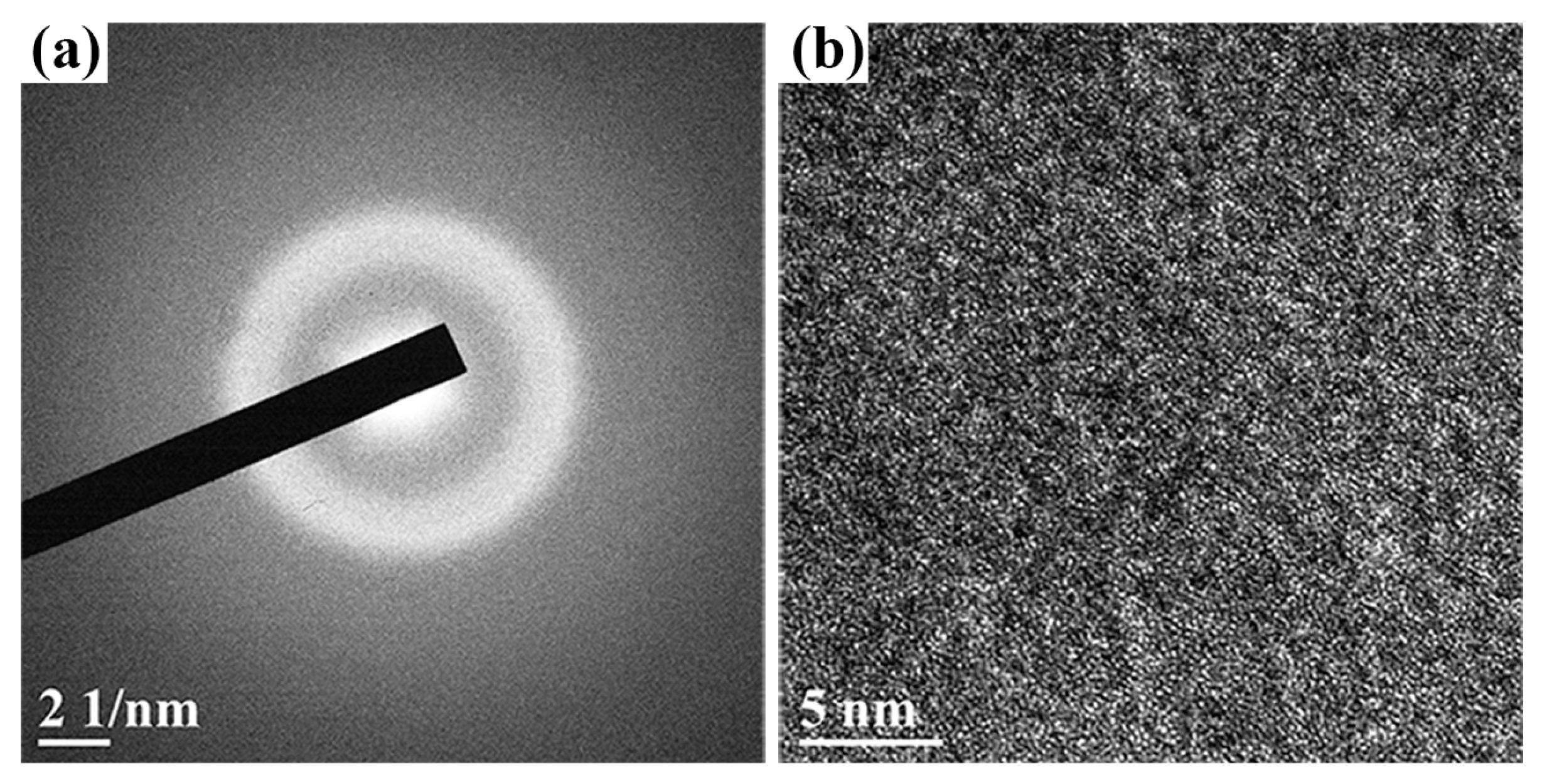
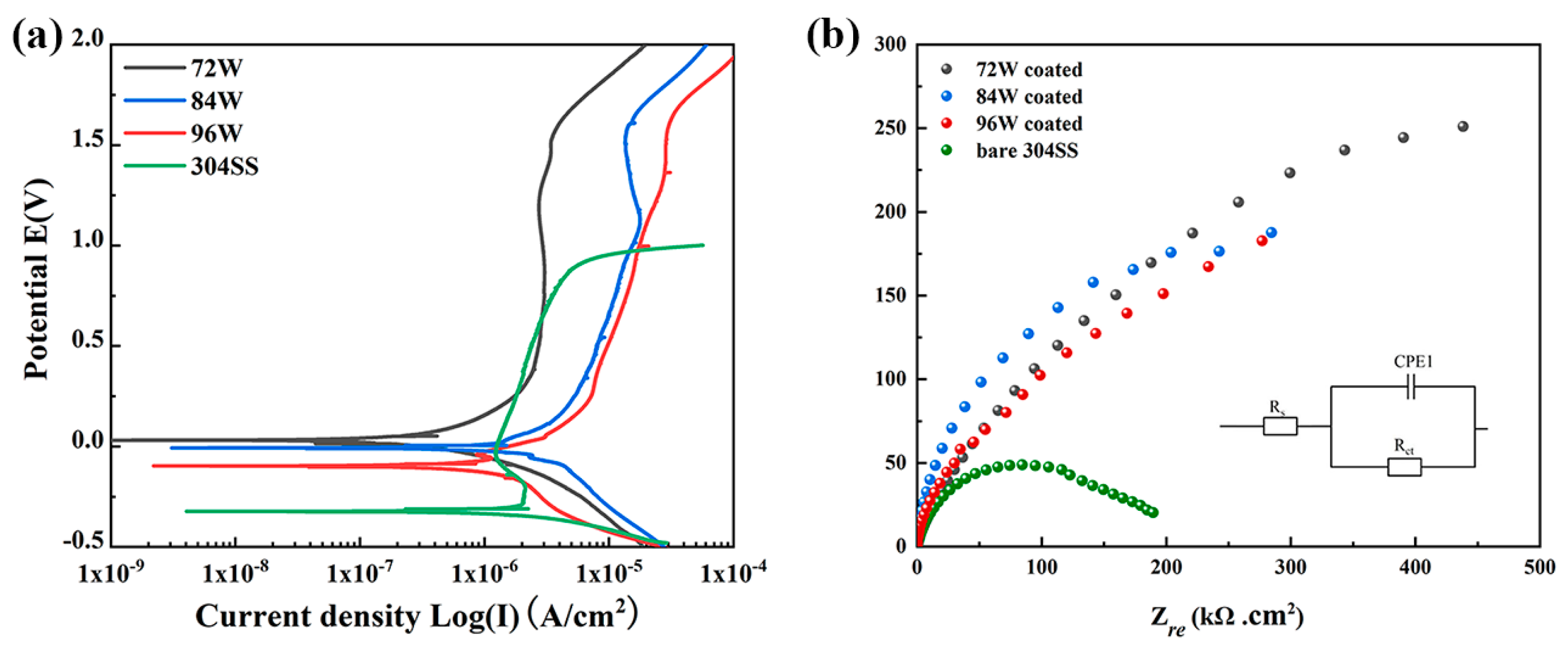
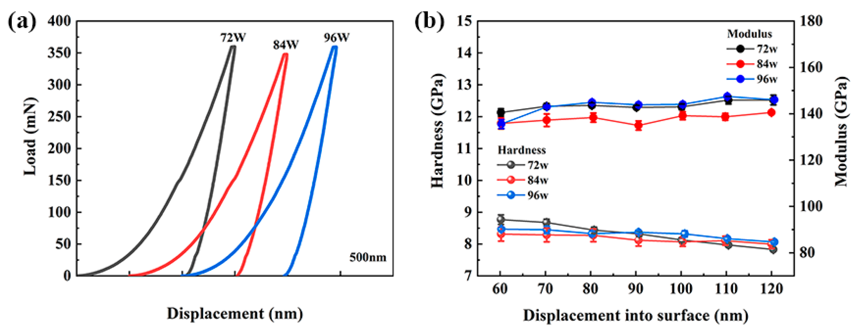
3. Results and Discussion
4. Conclusions
Supplementary Materials
Author Contributions
Funding
Conflicts of Interest
References
- Inoue, A. Bulk amorphous and nanocrystalline alloys with high functional properties. Mater. Sci. Eng. A 2001, 304, 1–10. [Google Scholar] [CrossRef]
- Inoue, A.; Shen, B.; Koshiba, H.; Kato, H.; Yavari, A.R. Cobalt-based bulk glassy alloy with ultrahigh strength and soft magnetic properties. Nat. Mater. 2003, 2, 661–663. [Google Scholar] [CrossRef] [PubMed]
- Du, X.H.; Huang, J.C.; Hsieh, K.C.; Lai, Y.H.; Chen, H.M.; Jang, J.S.C.; Liaw, P.K. Two-glassy-phase bulk metallic glass with remarkable plasticity. Appl. Phys. Lett. 2007, 91, 131901. [Google Scholar] [CrossRef]
- Ashby, M.F.; Greer, A.L. Metallic glasses as structural materials. Scr. Mater. 2006, 54, 321–326. [Google Scholar] [CrossRef]
- Duwez, P.; Lin, S.C.H. Amorphous Ferromagnetic Phase in Iron-Carbon-Phosphorus Alloys. J. Appl. Phys. 1967, 38, 4096–4097. [Google Scholar] [CrossRef]
- Jiang, H.R.; Wei, X.S.; Lu, W.F.; Liang, D.D.; Wen, Z.H.; Wang, Z.; Xiang, H.P.; Shen, J. Design of Cu–Zr–Al and Cu–Zr–Al-Sn bulk amorphous alloys with high glass-forming ability. J. Non-Cryst. Solids 2019, 521, 119531. [Google Scholar] [CrossRef]
- Yang, Y.J.; Xing, D.W.; Li, C.P.; Wei, S.D.; Sun, J.K.; Shen, Q.K. A new way of designing bulk metallic glasses in Cu–Ti–Zr–Ni system. Mater. Sci. Eng. A 2007, 448, 15–19. [Google Scholar] [CrossRef]
- Lu, X.; Nursulton, M.; Du, Y.; Liao, W. Structural and Mechanical Characteristics of Cu50Zr43Al7 Bulk Metallic Glass Fabricated by Selective Laser Melting. Materials 2019, 12, 775. [Google Scholar] [CrossRef]
- Sun, Y.J.; Qu, D.D.; Huang, Y.J.; Liss, K.D.; Wei, X.S.; Xing, D.W.; Shen, J. Zr–Cu–Ni–Al bulk metallic glasses with superhigh glass-forming ability. Acta Mater. 2009, 57, 1290–1299. [Google Scholar] [CrossRef]
- Liang, D.D.; Wei, X.S.; Chang, C.T.; Li, J.W.; Wang, X.M.; Shen, J. Effect of W addition on the glass forming ability and mechanical properties of Fe-based metallic glass. J. Alloy. Compd. 2018, 731, 1146–1150. [Google Scholar] [CrossRef]
- Shen, J.; Chen, Q.; Sun, J.; Fan, H. Exceptionally high glass-forming ability of an FeCoCrMoCBY alloy. Appl. Phys. Lett. 2005, 86, 279. [Google Scholar] [CrossRef]
- Li, H.X.; Lu, Z.C.; Wang, S.L.; Wu, Y.; Lu, Z.P. Fe-based bulk metallic glasses: Glass formation, fabrication, properties and applications. Prog. Mater. Sci. 2019, 103, 235–318. [Google Scholar] [CrossRef]
- Schneider, S.; Thiyagarajan, P.; Johnson, W.L. Formation of nanocrystals based on decomposition in the amorphous Zr41.2Ti13.8Cu12.5Ni10Be22.5 alloy. Appl. Phys. Lett. 1996, 68, 493–495. [Google Scholar] [CrossRef]
- Kündig, A.A.; Ohnuma, M.; Ping, D.H.; Ohkubo, T.; Hono, K. In situ formed two-phase metallic glass with surface fractal microstructure. Acta Mater. 2004, 52, 2441–2448. [Google Scholar] [CrossRef]
- Wang, W.H. Bulk Metallic Glasses with Functional Physical Properties. Adv. Mater. 2009, 21, 4524–4544. [Google Scholar] [CrossRef]
- Louzguine-Luzgin, D.V.; Saito, T.; Saida, J.; Inoue, A. Influence of cooling rate on the structure and properties of a Cu–Zr–Ti–Ag glassy alloy. J. Mater. Res. 2011, 23, 515–522. [Google Scholar] [CrossRef]
- Chu, J.P.; Huang, J.C.; Jang, J.S.C.; Wang, Y.C.; Liaw, P.K. Thin film metallic glasses: Preparations, properties, and applications. JOM 2010, 62, 19–24. [Google Scholar] [CrossRef]
- Chu, J.P.; Jang, J.S.C.; Huang, J.C.; Chou, H.S.; Yang, Y.; Ye, J.C.; Wang, Y.C.; Lee, J.W.; Liu, F.X.; Liaw, P.K.; et al. Thin film metallic glasses: Unique properties and potential applications. Thin Solid Films 2012, 520, 5097–5122. [Google Scholar] [CrossRef]
- Chou, H.S.; Huang, J.C.; Chang, L.W. Mechanical properties of ZrCuTi thin film metallic glass with high content of immiscible tantalum. Surf. Coat. Technol. 2010, 205, 587–590. [Google Scholar] [CrossRef]
- Chu, C.W.; Jang, J.S.C.; Chiu, S.M.; Chu, J.P. Study of the characteristics and corrosion behavior for the Zr-based metallic glass thin film fabricated by pulse magnetron sputtering process. Thin Solid Films 2009, 517, 4930–4933. [Google Scholar] [CrossRef]
- Sharma, P.; Zhang, W.; Amiya, K.; Kimura, H.; Inoue, A. Nanoscale patterning of Zr-Al-Cu-Ni metallic glass thin films deposited by magnetron sputtering. J. Nanosci. Nanotechnol. 2005, 5, 416–420. [Google Scholar] [CrossRef] [PubMed]
- Ketov, S.V.; Shi, X.; Xie, G.; Kumashiro, R.; Churyumov, A.Y.; Bazlov, A.I.; Chen, N.; Ishikawa, Y.; Asao, N.; Wu, H.; et al. Nanostructured Zr-Pd Metallic Glass Thin Film for Biochemical Applications. Sci. Rep. 2015, 5, 7799. [Google Scholar] [CrossRef] [PubMed]
- Kaushik, N.; Sharma, P.; Ahadian, S.; Khademhosseini, A.; Takahashi, M.; Makino, A.; Tanaka, S.; Esashi, M. Metallic glass thin films for potential biomedical applications. J. Biomed. Mater. Res. B Appl. Biomater. 2014, 102, 1544–1552. [Google Scholar] [CrossRef] [PubMed]
- Yu, C.C.; Wu, H.J.; Deng, P.Y.; Agne, M.T.; Snyder, G.J.; Chu, J.P. Thin-film metallic glass: An effective diffusion barrier for Se-doped AgSbTe2 thermoelectric modules. Sci. Rep. 2017, 7, 45177. [Google Scholar] [CrossRef] [PubMed]
- Chang, Y.Z.; Tsai, P.H.; Li, J.B.; Lin, H.C.; Jang, J.S.C.; Li, C.; Chen, G.J.; Chen, Y.C.; Chu, J.P.; Liaw, P.K. Zr-based metallic glass thin film coating for fatigue-properties improvement of 7075-T6 aluminum alloy. Thin Solid Films 2013, 544, 331–334. [Google Scholar] [CrossRef]
- Tsai, P.H.; Li, J.B.; Chang, Y.Z.; Lin, H.C.; Jang, J.S.C.; Chu, J.P.; Lee, J.W.; Liaw, P.K. Fatigue properties improvement of high-strength aluminum alloy by using a ZrCu-based metallic glass thin film coating. Thin Solid Films 2014, 561, 28–32. [Google Scholar] [CrossRef]
- Kobata, J.; Miura, K.-I.; Amiya, K.; Fukuda, Y.; Saotome, Y. Nanoimprinting of Ti–Cu-based thin-film metallic glasses deposited by unbalanced magnetron sputtering. J. Alloy. Compd. 2017, 707, 132–136. [Google Scholar] [CrossRef]
- Kelly, P.J.; Arnell, R.D. Magnetron sputtering: A review of recent developments and applications. Vacuum 2000, 56, 159–172. [Google Scholar] [CrossRef]
- Tsai, P.; Kranjc, K.; Flores, K.M. Hierarchical heterogeneity and an elastic microstructure observed in a metallic glass alloy. Acta Mater. 2017, 139, 11–20. [Google Scholar] [CrossRef]
- Rauf, A.; Fang, Y.N.; Zhang, H.X.; Peng, G.; Feng, T. Thickness effects on microstructure, mechanical and soft magnetic properties of sputtered Fe-Zr thin film metallic glass. J. Non-Cryst. Solids 2019, 521, 119500. [Google Scholar] [CrossRef]
- Zeman, P.; Zítek, M.; Zuzjaková, Š.; Čerstvý, R. Amorphous Zr-Cu thin-film alloys with metallic glass behavior. J. Alloy. Compd. 2017, 696, 1298–1306. [Google Scholar] [CrossRef]
- Rauf, A.; Guo, C.Y.; Fang, Y.N.; Yu, Z.; Sun, B.A.; Feng, T. Binary Cu-Zr thin film metallic glasses with tunable nanoscale structures and properties. J. Non-Cryst. Solids 2018, 498, 95–102. [Google Scholar] [CrossRef]
- Cheung, T.L.; Shek, C.H. Thermal and mechanical properties of Cu–Zr–Al bulk metallic glasses. J. Alloy. Compd. 2007, 434, 71–74. [Google Scholar] [CrossRef]
- Inoue, A.; Zhang, T.; Masumoto, T. Al-La-Ni Amorphous-Alloys with a Wide Supercooled Liquid Region. Mater. Trans. JIM 1989, 30, 965–972. [Google Scholar] [CrossRef]
- Kim, S.-Y.; Park, G.-H.; Kim, H.-A.; Lee, A.Y.; Oh, H.-R.; Lee, C.-W.; Lee, M.-H. Micro-deposition of Cu-based metallic glass wire by direct laser melting process. Mater. Lett. 2017, 202, 1–4. [Google Scholar] [CrossRef]
- Kramer, L.; Champion, Y.; Pippan, R. From powders to bulk metallic glass composites. Sci. Rep. 2017, 7, 6651. [Google Scholar] [CrossRef]
- Liu, Y.H.; Fujita, T.; Hirata, A.; Li, S.; Liu, H.W.; Zhang, W.; Inoue, A.; Chen, M.W. Deposition of multicomponent metallic glass films by single-target magnetron sputtering. Intermetallics 2012, 21, 105–114. [Google Scholar] [CrossRef]
- Moens, F.; Schramm, I.C.; Konstantinidis, S.; Depla, D. On the microstructure of magnesium thin films deposited by magnetron sputtering. Thin Solid Films 2019, 689, 137501. [Google Scholar] [CrossRef]
- Kim, Y.S.; Park, H.J.; Mun, S.C.; Jumaev, E.; Hong, S.H.; Song, G.; Kim, J.T.; Park, Y.K.; Kim, K.S.; Jeong, S.I.; et al. Investigation of structure and mechanical properties of TiZrHfNiCuCo high entropy alloy thin films synthesized by magnetron sputtering. J. Alloy. Compd. 2019, 797, 834–841. [Google Scholar] [CrossRef]
- Mitchell, D.R.; Petersen, T.C. RDFTools: A software tool for quantifying short-range ordering in amorphous materials. Microsc. Res. Tech. 2012, 75, 153–163. [Google Scholar] [CrossRef]
- Tang, J.L.; Zhu, Q.H.; Wang, Y.Y.; Apreutesei, M.; Wang, H.; Steyer, P.; Chamas, M.; Billard, A. Insights on the Role of Copper Addition in the Corrosion and Mechanical Properties of Binary Zr-Cu Metallic Glass Coatings. Coatings 2017, 7, 223. [Google Scholar] [CrossRef]
- Apreutesei, M.; Steyer, P.; Billard, A.; Joly-Pottuz, L.; Esnouf, C. Zr-Cu thin film metallic glasses: An assessment of the thermal stability and phases’ transformation mechanisms. J. Alloy. Compd. 2015, 619, 284–292. [Google Scholar] [CrossRef]
- Nayebossadri, S.; Smith, D.; Speight, J.; Book, D. Amorphous Zr-based thin films fabricated by magnetron sputtering for potential application in hydrogen purification. J. Alloy. Compd. 2015, 645, 56–60. [Google Scholar] [CrossRef]
- Saida, J.; Matsushita, M.; Li, C.; Inoue, A. Comparative study of grain growth behavior from a supercooled liquid region of Zr65Cu27.5Al7.5 and Zr65Cu35 metallic glasses. J. Mater. Sci. 2000, 35, 3539–3546. [Google Scholar] [CrossRef]
- Zhu, J.; Yang, M.; Wang, C.; Yang, S.; Han, J.; Xie, G.; Liu, X. Formation of two-glassy-phase bulk metallic glass in Zr-Co-Al-Y immiscible system. J. Alloy. Compd. 2019, 781, 8–12. [Google Scholar] [CrossRef]
- Chen, S.S.; Zhang, H.R.; Todd, I. Phase-separation-enhanced plasticity in a Cu47.2Zr46.5Al5.5Nb0.8 bulk metallic glass. Scr. Mater. 2014, 72, 47–50. [Google Scholar] [CrossRef]
- He, J.; Mattern, N.; Kaban, I.; Dai, F.P.; Song, K.K.; Yan, Z.J.; Zhao, J.Z.; Kim, D.H.; Eckert, J. Enhancement of glass-forming ability and mechanical behavior of zirconium-lanthanide two-phase bulk metallic glasses. J. Alloy. Compd. 2015, 618, 795–802. [Google Scholar] [CrossRef]
- Suryanarayana, C.; Inoue, A. Bulk Metallic Glasses, 2nd ed.; CRC Press: Boca Raton, FL, USA, 2017. [Google Scholar]
- Takeuchi, A.; Inoue, A. Classification of bulk metallic glasses by atomic size difference, heat of mixing and period of constituent elements and its application to characterization of the main alloying element. Mater. Trans. 2005, 46, 2817–2829. [Google Scholar] [CrossRef]
- Meijering, J.L. Segregation in regular ternary solutions, part I. Philips. Res. Rep. 1950, 5, 333–356. [Google Scholar]
- Meijering, J.L. Segregation in regular ternary solutions, part II. Philips. Res. Rep. 1950, 6, 183–210. [Google Scholar]
- Barbee, T.W.; Walmsley, R.G.; Marshall, A.F.; Keith, D.L.; Stevenson, D.A. Phase separation in vapor quench synthesized noncrystalline copper zirconium alloys. Appl. Phys. Lett. 1981, 38, 132–135. [Google Scholar] [CrossRef]
- Park, E.S.; Chang, H.J.; Kim, D.H. Effect of addition of Be on glass-forming ability, plasticity and structural change in Cu–Zr bulk metallic glasses. Acta Mater. 2008, 56, 3120–3131. [Google Scholar] [CrossRef]
- Sanditov, D.S.; Ojovan, M.I. On relaxation nature of glass transition in amorphous materials. Phys. B 2017, 523, 96–113. [Google Scholar] [CrossRef]
- Stephenson, G.B. Spinodal Decomposition in Amorphous Systems. J. Non-Cryst. Solids 1984, 66, 393–427. [Google Scholar] [CrossRef]
- Jiang, H.-R.; Bochtler, B.; Frey, M.; Liu, Q.; Wei, X.-S.; Min, Y.; Riegler, S.S.; Liang, D.-D.; Busch, R.; Shen, J. Equilibrium viscosity and structural change in the Cu47.5Zr45.1Al7.4 bulk glass-forming liquid. Acta Mater. 2020, 184, 69–78. [Google Scholar] [CrossRef]
- Liu, L.; Liu, B. Influence of the micro-addition of Mo on glass forming ability and corrosion resistance of Cu-based bulk metallic glasses. Electrochim. Acta 2006, 51, 3724–3730. [Google Scholar] [CrossRef]
- Schuh, C.; Hufnagel, T.; Ramamurty, U. Mechanical behavior of amorphous alloys. Acta Mater. 2007, 55, 4067–4109. [Google Scholar] [CrossRef]
- Ma, Y.; Peng, G.J.; Chen, H.; Jiang, W.F.; Zhang, T.H. On the nanoindentation hardness of Cu–Zr–Al/Cu nanolaminates. J. Non-Cryst. Solids 2018, 482, 208–212. [Google Scholar] [CrossRef]
- Ghidelli, M.; Volland, A.; Blandin, J.-J.; Pardoen, T.; Raskin, J.-P.; Mompiou, F.; Djemia, P.; Gravier, S. Exploring the mechanical size effects in Zr65Ni35 thin film metallic glasses. J. Alloy. Compd. 2014, 615, 90–92. [Google Scholar] [CrossRef]


| Samples | Power (W) | Thickness (μm) | Deposition Rate (nm/min) | Composition (at. %) |
|---|---|---|---|---|
| a | 36 | 0.584 | 19.5 | Cu44Zr33Al23 |
| b | 48 | 0.723 | 24.1 | Cu43Zr37Al20 |
| c | 60 | 1.103 | 36.8 | Cu44Zr38Al18 |
| d | 72 | 1.147 | 38.2 | Cu49Zr38Al13 |
| e | 84 | 1.282 | 42.7 | Cu52Zr38Al10 |
| f | 96 | 1.252 | 41.7 | Cu51Zr38Al11 |
| Samples | Corrosion Properties | Mechanical Properties | References | |||||||
|---|---|---|---|---|---|---|---|---|---|---|
| Solution | Ecorr (mV) | Icorr (μA·cm−2) | Ipass (μA·cm−2) | Epit (mV) | Corrosion Rate (10−3 mmpy) | Rct (kΩ·cm2) | Hardness (GPa) | Modulus (GPa) | ||
| 72 W | 1 M H2SO4 | 31.3 | 0.79 | 2.59 | 1.56 | 10.6 | 200.4 | 7.77 | 145.92 | This work |
| 84 W | −3.79 | 4.98 | 17.14 | 1.59 | 18.5 | 125.2 | 8.18 | 136.80 | This work | |
| 96 W | −117 | 7.98 | 1.29 | 1.53 | 19.1 | 85.50 | 8.17 | 140.89 | This work | |
| 304SS | −323 | 1.05 | 2.05 | −27.5 | 25.1 | 49.45 | − | − | This work | |
| Cu-Zr coating | 0.01 M H2SO4 | −500 | 100 | − | − | − | − | 3.90 | 114.30 | [32,41] |
| Cu47Zr11Ti34Ni8 BMG | 1 M H2SO4 | −427 | − | − | − | 15.3 | − | − | − | [57] |
© 2019 by the authors. Licensee MDPI, Basel, Switzerland. This article is an open access article distributed under the terms and conditions of the Creative Commons Attribution (CC BY) license (http://creativecommons.org/licenses/by/4.0/).
Share and Cite
Wei, X.; Ying, C.; Wu, J.; Jiang, H.; Yan, B.; Shen, J. Fabrication, Corrosion, and Mechanical Properties of Magnetron Sputtered Cu–Zr–Al Metallic Glass Thin Film. Materials 2019, 12, 4147. https://doi.org/10.3390/ma12244147
Wei X, Ying C, Wu J, Jiang H, Yan B, Shen J. Fabrication, Corrosion, and Mechanical Properties of Magnetron Sputtered Cu–Zr–Al Metallic Glass Thin Film. Materials. 2019; 12(24):4147. https://doi.org/10.3390/ma12244147
Chicago/Turabian StyleWei, Xianshun, Chengxi Ying, Jing Wu, Haoran Jiang, Biao Yan, and Jun Shen. 2019. "Fabrication, Corrosion, and Mechanical Properties of Magnetron Sputtered Cu–Zr–Al Metallic Glass Thin Film" Materials 12, no. 24: 4147. https://doi.org/10.3390/ma12244147
APA StyleWei, X., Ying, C., Wu, J., Jiang, H., Yan, B., & Shen, J. (2019). Fabrication, Corrosion, and Mechanical Properties of Magnetron Sputtered Cu–Zr–Al Metallic Glass Thin Film. Materials, 12(24), 4147. https://doi.org/10.3390/ma12244147