Article

Synthesis and Mechanical Characterization of a Ti(C,N)/Mo–Co–Ni/CaF2@Al2O3 Self-Lubricating Cermet

School of Mechanical and Automotive Engineering, Qilu University of Technology (Shandong Academy of Sciences), Jinan 250353, China
*
Author to whom correspondence should be addressed.
Materials 2019, 12(23), 3981; https://doi.org/10.3390/ma12233981
Submission received: 15 October 2019 / Revised: 21 November 2019 / Accepted: 23 November 2019 / Published: 30 November 2019

Abstract

:
In this paper, an Al2O3 coated CaF2 (CaF2@Al2O3) nanocomposite powder is used as the additive phase of a Ti(C,N)-based self-lubricating cermet material. A novel self-lubricating ceramic material with a multilayer core–shell microstructure was prepared using a vacuum hot-pressing sintering process. The results show that the surface of the CaF2 powder is coated with Al2O3, and when introduced into a Ti(C,N)–Mo–Co–Ni material system, it can utilize the high-temperature liquid phase diffusion mechanism of the metal Mo–Co–Ni phase in the sintering process. The CaF2@Al2O3@Mo–Co–Ni multilayer core–shell microstructure is formed in the material. Compared with the direct addition of CaF2 and Al2O3, the hardness and fracture toughness of the material are increased by 24.31% and 22.56%, reaching 23.93 GPa and 9.94 MPa·m1/2, respectively. The formation of the multilayer core–shell microstructure is the main reason for the improvement of the mechanical properties of the material.

1. Introduction

Ti(C,N)-based cermet is a new type of cermet with a high hardness, high strength, good high temperature wear resistance, good toughness, low density, and high thermal conductivity [1]. The successful replacement of tungsten-based hard alloys in many applications is of great significance for strategically saving the resources of rare metal tungsten [2].
Relevant scholars have done a lot of research on improving the performance of cermet [3,4,5]. Xiang et al. [6] prepared a Ti(C0.5N0.5) powder with a particle size of less than 100 nm using the sol–gel method. Monteverde et al. [7] studied the synthesis of fine pure Ti(C,N) powders using nano-TiN and C powders as raw materials. Qu et al. [8] showed that liquid Ni–Co has a good wettability between the hard phase and the bonded phase during high temperature sintering. The results of Deng et al. [9] show that β-Co particles can optimize the microstructure of cermet and obtain excellent mechanical properties. Wu et al. [10] studied the effects of different proportions of rare metal cobalt contents on the microstructure of Ti(C,N)-based cermet materials. The results show that the core thickness of the hard particles change when Ni is replaced by Co. Xu et al. [11] showed that increasing the Ni and Co binder phase content can not only improve the solid solution reaction and the wetting of the hard phase, but also increase the thickness of the ring phase. Zhang et al. [12] studied the effect of sintering temperature on the microstructure of Al2O3-Ti(C,N)-cBN cermet. The results show that the suitable sintering temperature of Al2O3–Ti(C,N)–cBN is 1400~1500 °C [13].
Nano-particles toughen, that is, nano-particles are added into cermet to achieve the effect of strengthening and toughening by using fine-grain strengthening, bridging, a pulling-out effect, and crack deflection [14]. In order to improve the performance of ceramic materials, nano-CaF2 has been studied by a large number of scholars [15]. However, the application of nano-CaF2 is limited because of its high coefficient of thermal expansion [16]. As a result of the high thermal expansion coefficient of calcium fluoride, larger residual stress is generated [17].
In recent years, core–shell composites prepared using coating powders have been widely used in the preparation of various composite materials, such as ceramics or cemented carbides [18]. Han et al. [19] prepared porous alumina ceramics using C@Al2O3 microspheres as a pore former. Zhao et al. [20] successfully prepared core–shell composite microspheres of a nickel core and alumina nanosheet shell using the hydrothermal deposition method, and the electromagnetic absorption performance of the core–shell microspheres was significantly improved. Han et al. [21] prepared a nano-TiO2@Fe micro-scale photocatalyst with a core–shell structure using the precipitation method, which significantly improved the photocatalytic activity of the material. Wang et al. [22] used aluminum hydroxide to coat Eg particles in order to form a composite particle (Eg@ATH) with a core–shell structure, in order to improve the flame-retardant properties of expanded graphite in rigid polyurethane foam.
The aim of this study was to create a Ti(C,N)-based cermet material with a multilayer core–shell microstructure (CaF2@Al2O3@Mo–Co–Ni), and to evaluate it regarding its influence on the mechanical properties.

2. Experiment

2.1. Sample Preparation

Distilling water, xylene, and absolute ethanol were mixed at a volume ratio of 1:2:7 to obtain a mixed solution. The weighed Ca(NO)3) and NH4F were separately dispersed in the above mixed solution to obtain a Ca(NO)3 solution and NH4F solution. Polyvinylpyrrolidone (PVP) was mixed with absolute ethanol to obtain a suspension. The suspension was added to the above Ca(NO)3 solution and NH4F solution in equal amounts, respectively, and was then ultrasonically dispersed and mechanically stirred to obtain a final Ca(NO)3 solution and NH4F solution. The Ca(NO)3 solution was slowly added to the NH4F solution, sonicated, and stirred at 70~80 °C for 20~30 min, then cooled, centrifuged, and washed to obtain nano-CaF2.
A uniform thickness Al(OH)3 coating layer was formed on the surface of the CaF2 powder by controlling the Al3+ concentration of the solution, the reaction time, the water bath temperature, and the pH of the solution after the reaction. The Al(NO3)3·9H2O, Polyethylene glycol (PEG, MW 6000), and nano-CaF2 powders were mixed. The mixed solution was subjected to mechanical stirring and ultrasonic dispersion so as to obtain a suspension of the desired solubility of the experiment. When the solution was heated to 70 °C, the NH3·H2O was slowly dropped until the pH was adjusted to the setting value (7.5). Stirring was continued for 1 h in order to complete the reaction. At this time, the Al(OH)3 colloid gradually coated the nano-CaF2. The solution was centrifuged and washed to obtain the CaF2@Al(OH)3 coated powder. The CaF2@Al(OH)3 coated powder was put into a vacuum drying oven (DZF-6050) for 12 h. The dried CaF2@Al(OH)3 coated powder was placed in a YFX5/13Q-YC box type electric resistance furnace and calcined at 1000 °C. Finally, a core–shell coated powder (CaF2@Al2O3) with an outer layer of Al2O3 and a core of CaF2 was prepared.
Ti(C,N) was used as the matrix material, and the selected Ti(C,N) had an average particle diameter of 0.5 μm and a purity of more than 99.9%. Molybdenum, cobalt, and nickel were used as the metal bonding phases, and the selected average particle diameters were 1~3 μm and the purities were 99.9%. The MgO sintering aid had a selected average particle diameter of 1 μm and a purity of 99.9%. The nano-Al2O3 had a selected average particle diameter of 500 nm and a purity of 99.9%. The CaF2@ Al2O3 coated powder was obtained by the experiments, and had an average particle diameter of 50 nm. Three kinds of cermet materials were prepared, according to the condition that only the nano-CaF2 and the nano-Al2O3 were added without adding the coated powder, and the powder was coated with CaF2@Al2O3 in a volume ratio of 10%. The mixture was subjected to wet ball milling, uniformly dispersed by ultrasonic dispersion, vacuum dried, and sieved through 120 mesh. The mixed powder was placed in a tubular graphite mold and underwent cold pressing (20MPa) for 30 min in order to compact the powder to reduce the pores, and then the mold was placed in a sintering furnace for vacuum hot-pressing sintering. The sintering temperature was 1450 °C, the sintering pressure was 30 MPa, and the holding time was 30 min. Finally, the Ti(C,N)/Mo–Co–Ni/10 vol %CaF2@Al2O3 cermet material with a multilayer core–shell microstructure was prepared.

2.2. Testing and Characterization

The cross-sectional microstructure of the obtained cermet material was observed using a scanning electron microscope (SEM; Hitachi Regulus8220, 5 kV, 30,000×, Tokyo, Japan) and high-resolution transmission electron microscope (HRTEM; FEI TecnaiG2F20, 200 kV, 50,000×, Hillsboro, America). The phase composition of the coated powder and the cermet material was analyzed by X-ray diffraction (XRD; XRD-6100, Co, 3 kw, 2θ: 10~90°, Kyoto, Japan) and an energy dispersive spectrometer (EDS; Hitachi S4800, 20 keV, 500×, Tokyo, Japan). The morphology and phase compositions of the CaF2@Al2O3 coated powder were analyzed using a transmission electron microscope (TEM; JEOL JEM2100, 200 kV, 40,000×, Tokyo, Japan) and scanning electron microscope (SEM; Hitachi Regulus8220, 10 kV, 6000×, Tokyo, Japan).
The prepared Ti(C,N)-based cermet disk was cut with an inner circular slicer (J5060C-1, Beijing, China), and then ground and polished with a diamond abrasive paste to finally prepare a standard test strip of 3 mm × 4 mm × 30 mm. The bending strength of the spline was measured by a three-point bending method using an electronic universal testing machine (AGS-X5KN, Kyoto, Japan), with a span of 20 mm and a loading rate of 0.5 mm/min. The hardness was measured using an Hv-120 Vickers hardness tester, and the pressurization load was 196 N and the pressure was maintained for 15 s. The indentation morphology was observed using a super depth of field three-dimensional observation microscopy system (VHX-5000, Osaka, Japan), and the two indentations and the length of the indentation diagonal were measured and recorded. The relative density of the cermet material was tested and calculated using the Archimedes drainage method.

3. Results and Discussion

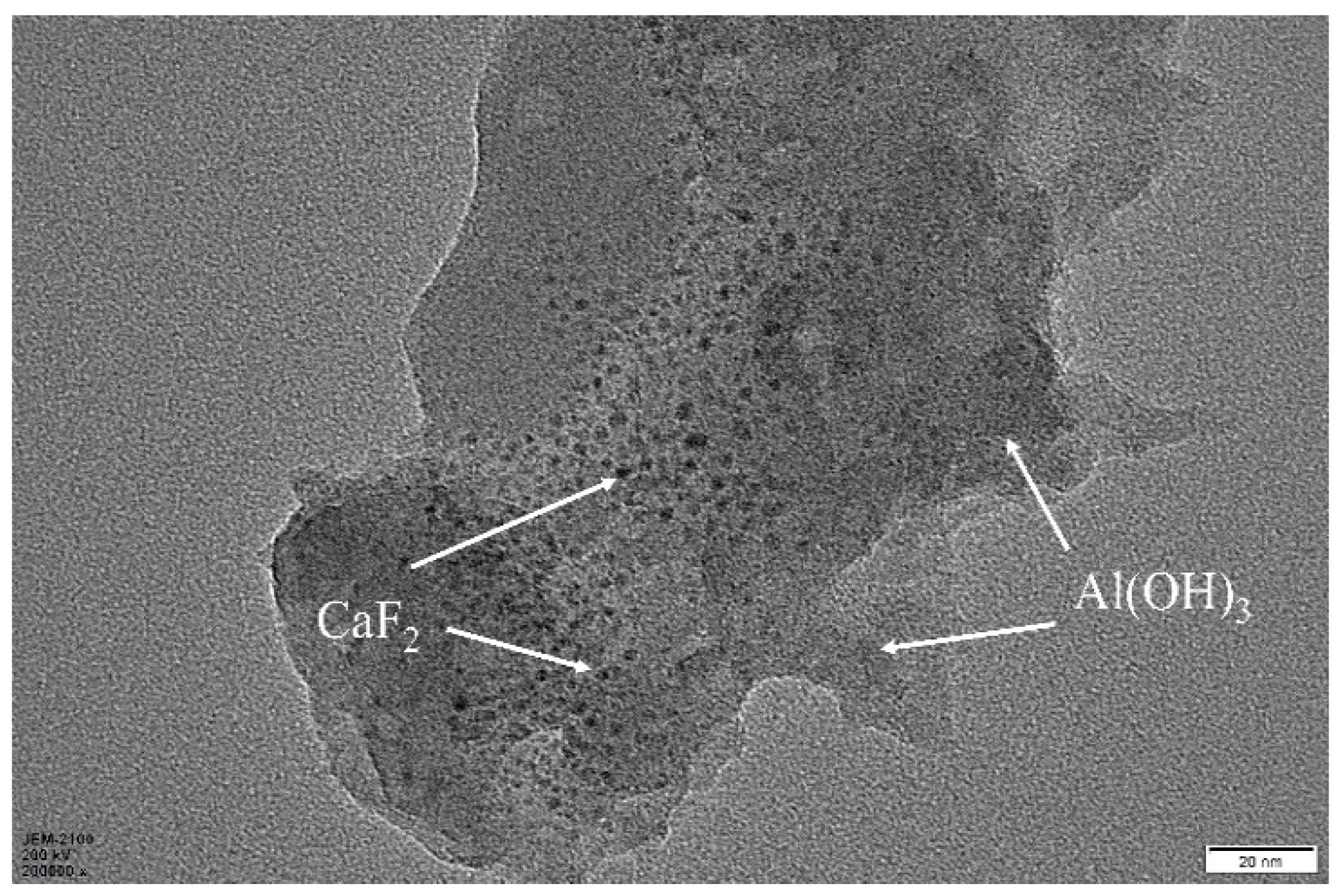
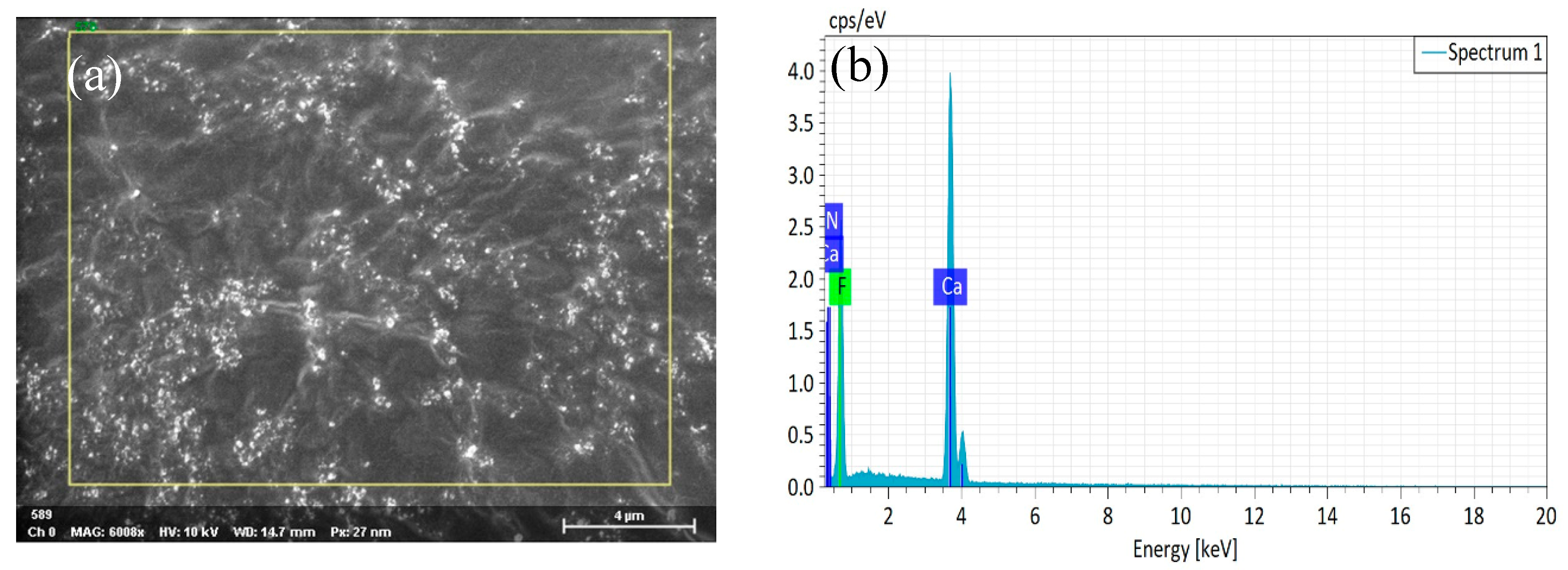
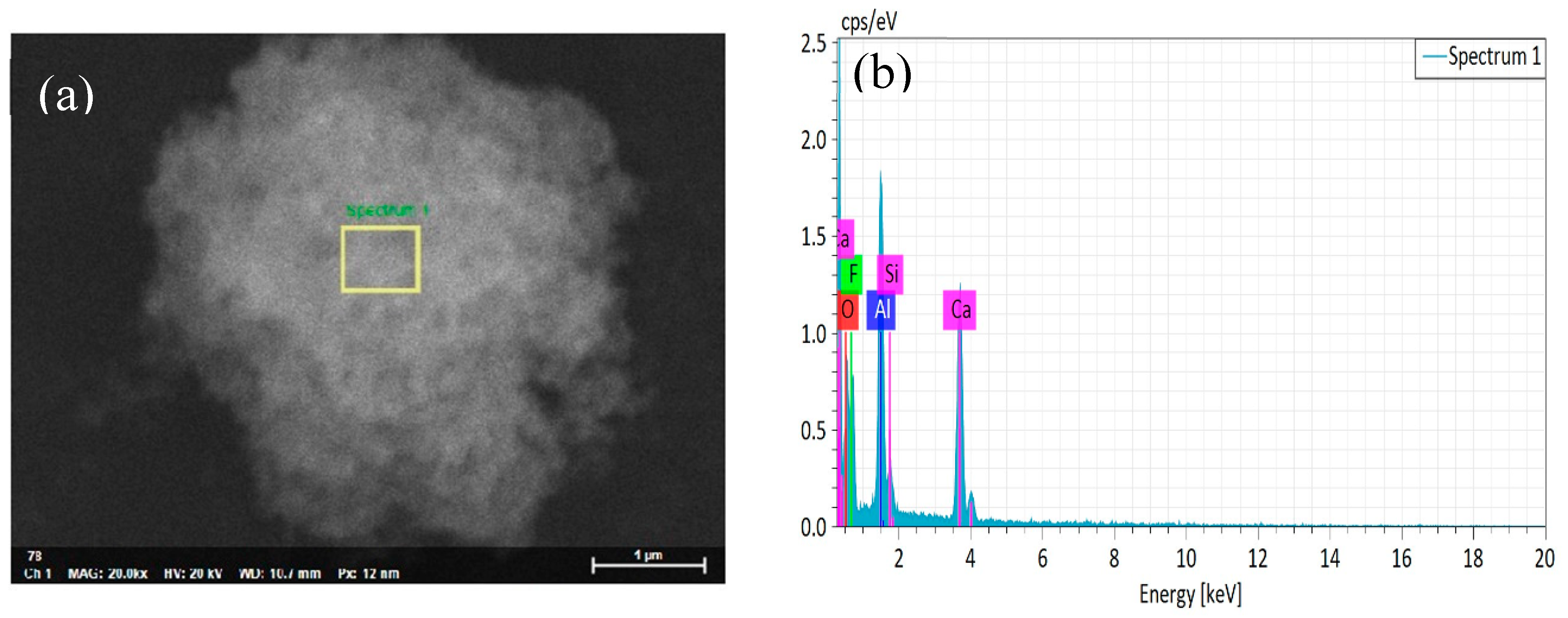
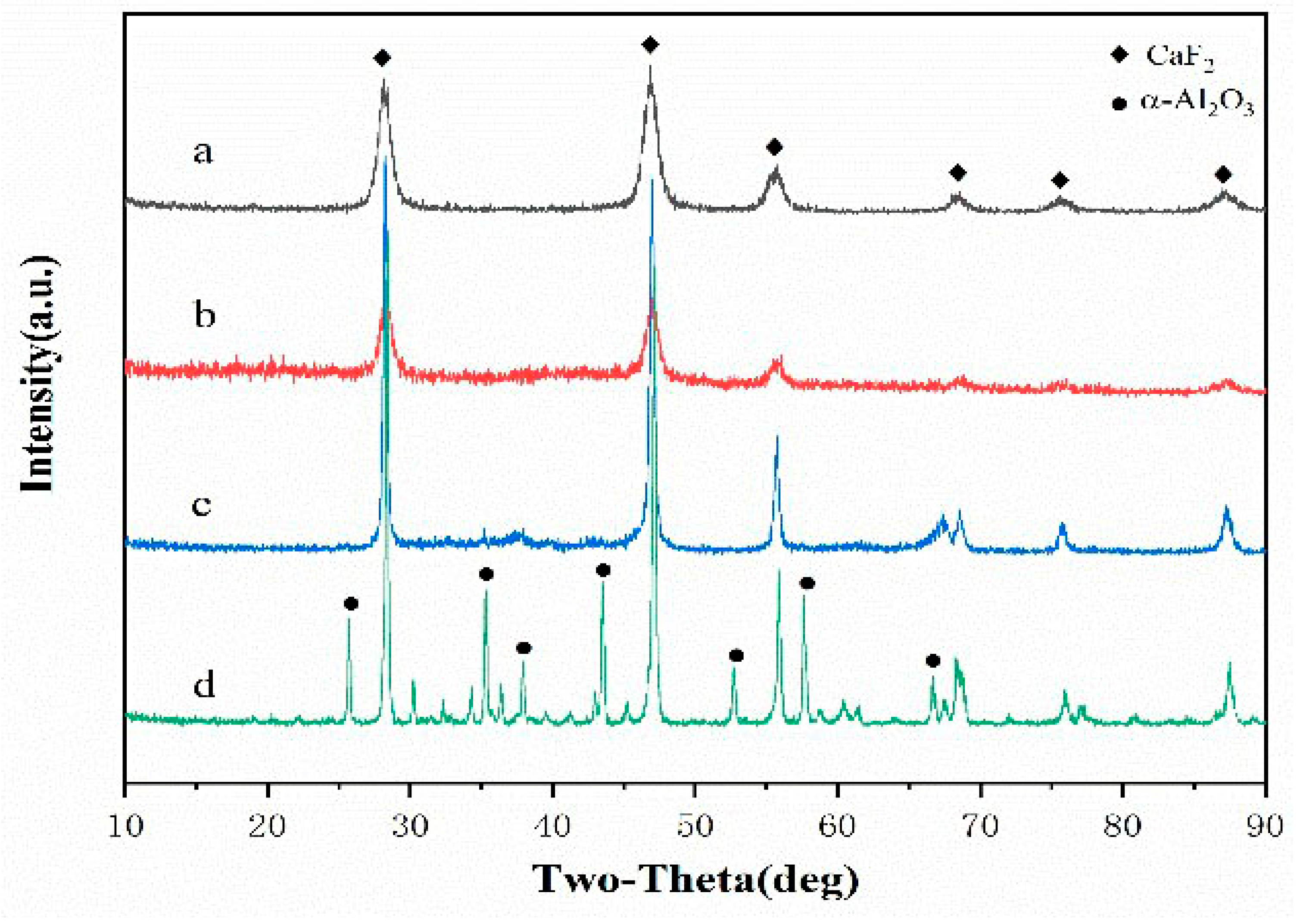
3.1. Phase Analysis of the Coated Powder

Figure 1 shows the transmission electron micrograph of the nano-CaF2 particles. The experimental results show that the nano-CaF2 particles were spherical particles with a particle size of 10~20 nm, and the surface morphology of the particles was clear and complete. During the experiment, PVP was not sensitive to the pH value, and as a dispersing agent, it had less influence on the experimental process and a better dispersion effect [23]. In addition, the preparation of nano-CaF2 was carried out in pure water, and the calcium fluoride had different particle size [24]. If the experiment had been carried out in a hydroalcoholic mixed solution, the prepared nano-CaF2 would be small and severely agglomerated [25]. Therefore, a mixed solution of xylene, water, and ethanol was used as a solvent for preparing the CaF2. The experimental results show that the prepared nano-CaF2 had a moderate particle size, and the dispersion effect of the nano-CaF2 particles was better. Nano-CaF2 particles with a moderate particle size were obtained, and the excessive agglomeration of the nanoparticles was effectively avoided.
Figure 2 shows the transmission electron micrograph of the prepared CaF2@Al(OH)3 coated particles. A non-uniform nucleation method was used to control the concentration of the coating, so that the Al3+ concentration was between homogeneous nucleation and heterogeneous nucleation. By controlling the liquid environment and the process of nucleation and growth, it was possible to obtain a coated powder in which the coating layer was precisely controlled. As shown in the figure, the Al(OH)3 colloidal molecules were uniformly and stably adsorbed on the surface of the CaF2 nanoparticles to form CaF2@Al(OH)3 coated particles with a core–shell microstructure.
Figure 3a shows the scanning electron micrograph of the nano-CaF2 particle powder. We could clearly observe the surface morphology of the untreated nano-CaF2 granules. The surface of the nano-CaF2 particles was completely smooth and uniform in particle size, and was approximately spherical. Through the EDS map analysis, there were only Ca and F elements on the surface of the particles, and there was no impurity element, indicating that the prepared CaF2 particles had a high purity. Figure 4a shows that a dense coating layer was formed on the surface of the CaF2. The surface of the coating layer was composed of a large number of spherical particles, and the spherical particles were stacked and connected to each other. Through the Figure 4b analysis of the elements, compared with Figure 3b, the coated particles surface contained not only Ca and F elements, but also higher Al and O elements. In addition, the content of the Ca and F elements was significantly lower than that of the CaF2 particles, indicating that a large amount of Al2O3 was coated on the surface of CaF2, and the Al2O3 coating layer was uniform and complete.
Figure 5a shows the X-ray diffraction pattern of the nano-CaF2 prepared in the above experiment. As can be seen from Figure 5a, the diffraction peak was completely a characteristic peak of CaF2, and no impurity peak appeared, indicating that the CaF2 nanopowder had a good purity. The characteristic of the powder to conform to the crystal structure of fluorite, and the use of the dispersant did not affect the crystal structure of CaF2. In addition, the CaF2 spectrum not only had a sharp peak shape, but also a high intensity, indicating that its crystallinity was good. Al(OH)3 was formed on the surface of CaF2 by the heterogeneous nucleation method, and the fully reacted CaF2@Al(OH)3 suspension was placed in a vacuum drying oven and dried at 80 °C. After drying for 24 h, the CaF2@Al(OH)3 coated powder was obtained. Figure 5b shows an X-ray diffraction pattern of the CaF2@Al(OH)3 coated powder. It can be seen from the figure that the intensity of the diffraction peak was significantly reduced after the CaF2 was coated. As Al(OH)3 is a colloid and does not have a crystal structure, there was no phase of Al(OH)3. The CaF2@Al(OH)3 powder was calcined at a high temperature of 800 °C. Figure 5c shows the powder X-ray diffraction spectrum obtained after the calcination was completed. It can be clearly observed that the diffraction peak of CaF2 was sharper and the peak intensity was further enhanced. This indicates that high-temperature calcination improves the crystallinity of CaF2. In comparison with the CaF2 diffraction pattern in Figure 5a, it can be observed that the diffraction peak of Al2O3 started to appear in the spectrum of the coated powder, and there was no peak for the other phases. It was in good agreement with the CaF2 standard map, indicating that high-temperature calcination caused Al(OH)3 to form Al2O3. Figure 5d shows that the CaF2@Al(OH)3 powder was calcined at a high temperature of 1000 °C, and was subjected to X-ray diffraction analysis. Compared with the diffraction pattern of Figure 5c, it is clearly observed that the Al2O3 diffraction peak was significantly enhanced. The diffraction peak was completely a characteristic peak of α-Al2O3, and the CaF2@Al(OH)3 coated powder was calcined and finally converted into the CaF2@Al2O3 coated powder. In addition, the peak of CaF2 was sharper, and the crystallinity of CaF2 was enhanced, which helps to improve the self-lubricating effect of the cermet material. In addition, the CaF2@Al2O3 coated powder did not produce other substances during the high-temperature calcination process, indicating that the chemical compatibility of CaF2 and Al2O3 was better.

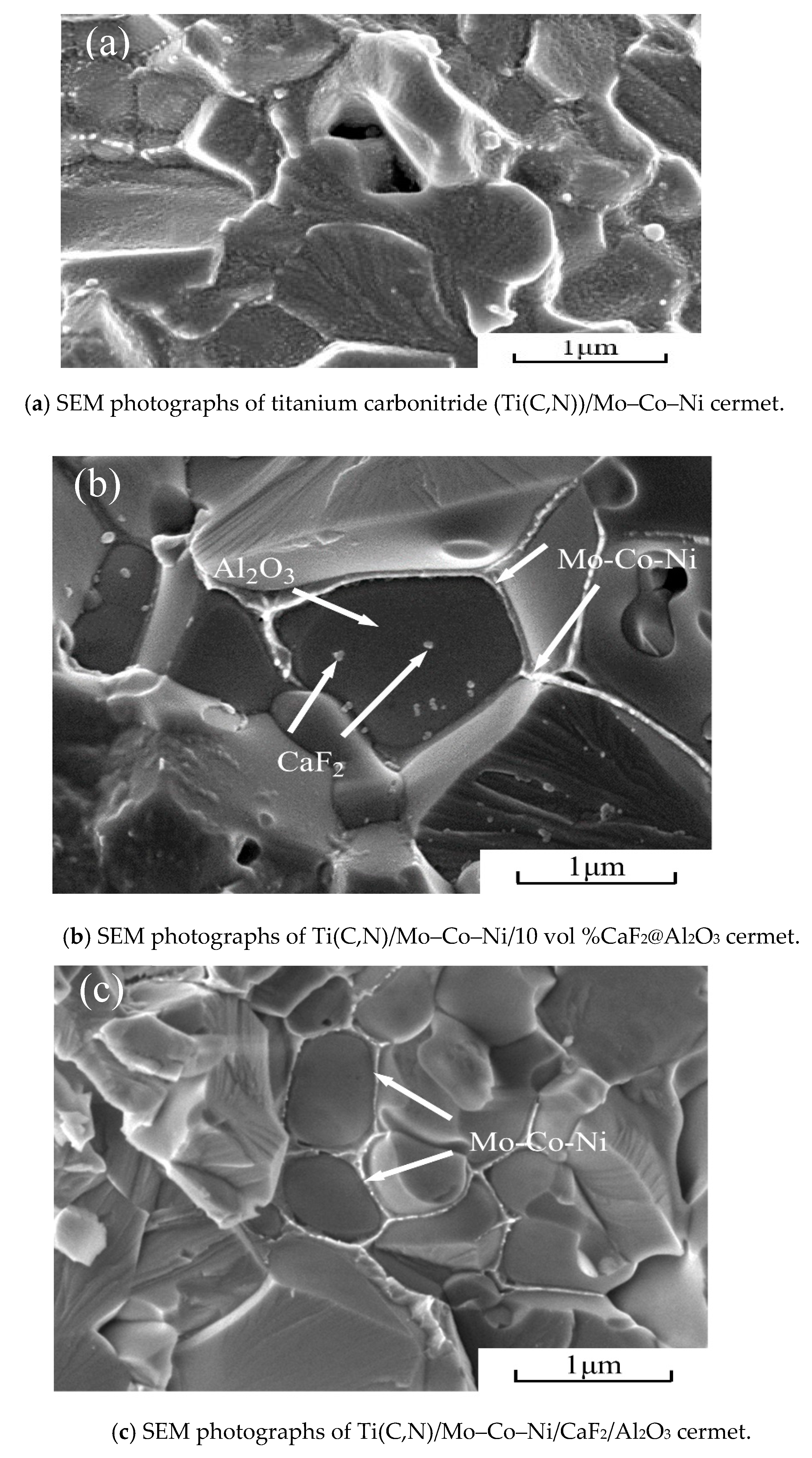
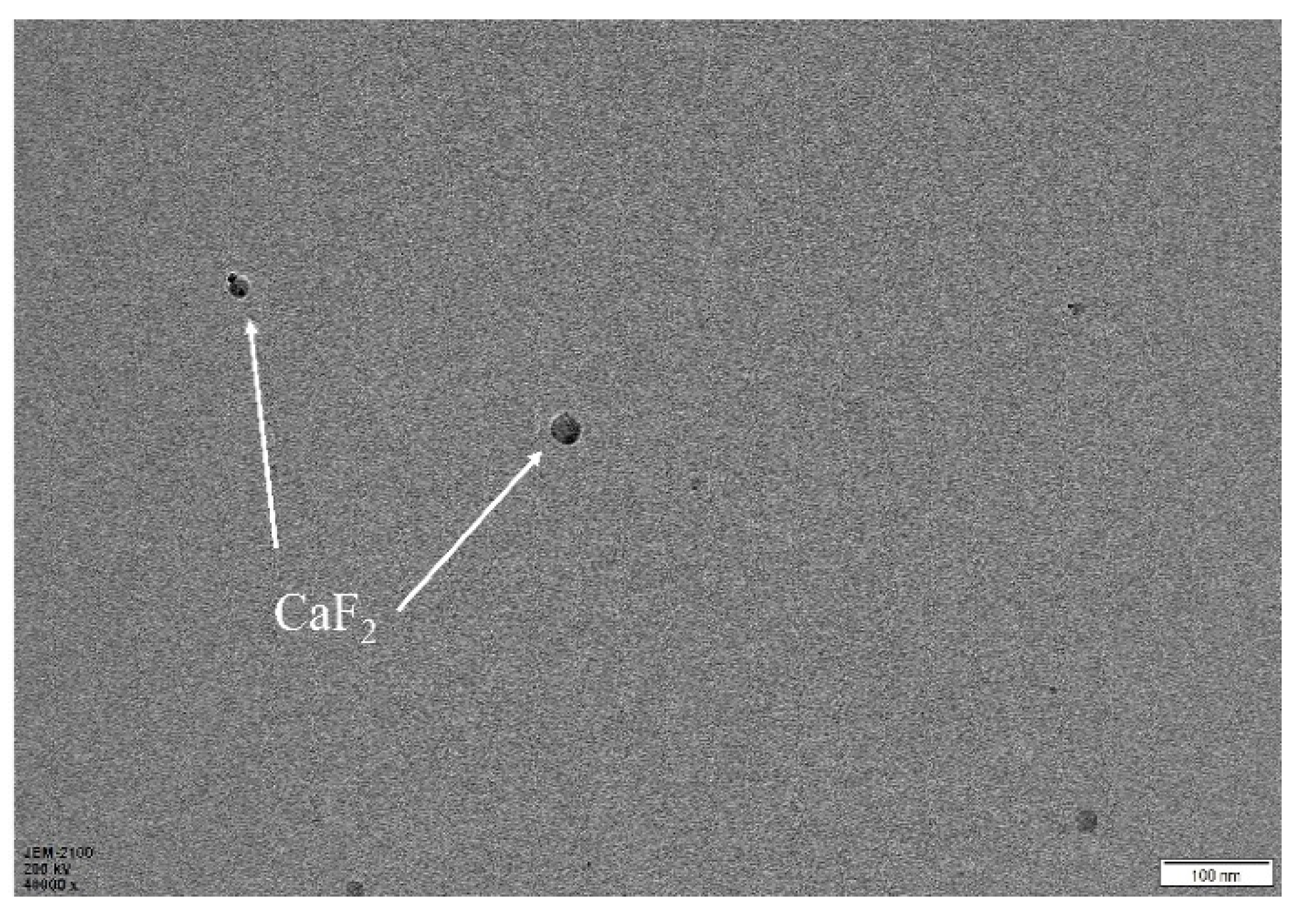
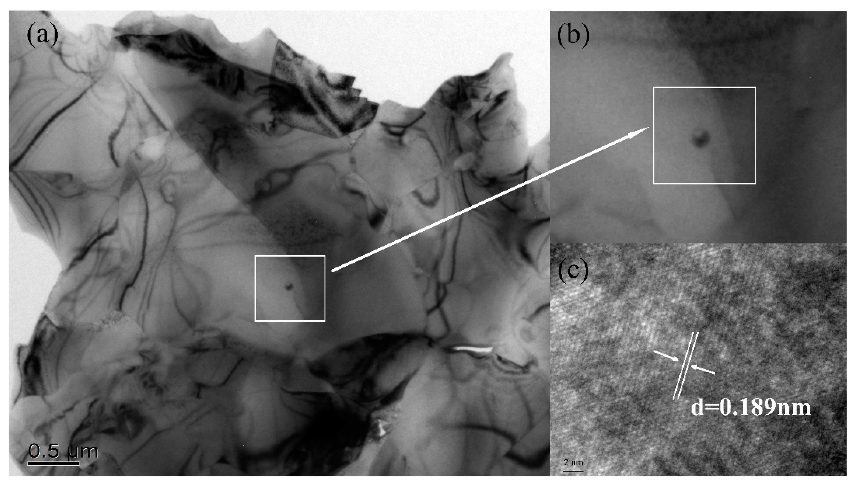
3.2. Metal Ceramic Material Microstructure

Figure 6a shows the fracture morphology of the Ti(C,N)/Mo–Co–Ni cermet material. We could clearly observe the grain shape of the material matrix, but the surface was covered with a metal binder phase. The results show that the fracture occurred at the grain boundary, and mainly expanded inside the metal bonded phase. Figure 6b shows the fracture morphology of the Ti(C,N)/Mo–Co–Ni/10 vol %CaF2@Al2O3 cermet material. Because of the addition of a certain amount of CaF2@Al2O3 coated powder, the microstructure of the multilayer core–shell can be clearly observed from the position marked in the figure. Not only was the metal bond coated with Al2O3, but nano-CaF2 particles were also found inside the Al2O3. Finally, the nano-CaF2 particles were used as the core, and the Al2O3 coated on the outer layer of CaF2 was used as the intermediate layer to form the multilayer core–shell microstructure of the Mo–Co–Ni metal bond phase in the outer layer of Al2O3. In addition, the step formed after the grain breakage can be clearly observed in Figure 6b, and after the grain breakage, we could observe the clear and complete nano-CaF2 particles. It has been indicated that there were both intergranular and transgranular fractures after the cermet material fracture. Figure 6c shows the fracture morphology of the Ti(C,N)/Mo–Co–Ni/CaF2/Al2O3 cermet material. As the CaF2 particles were not coated with Al2O3, CaF2 was not found in the crystal. This type of cermet was not found to form a multilayer core–shell microstructure.
Figure 7a shows an HRTEM photograph of the Ti(C,N)/Mo–Co–Ni/10 vol%CaF2@Al2O3 self-lubricating cermet material. We can clearly see the spherical nanoparticles in the figure. Where (b) is an enlarged picture of the selected area in (a), and (c) is an enlarged picture of the selected area in (b). The results of the high-resolution transmission electron microscopy show that the nanoparticles in the crystal were CaF2 crystals with a typical crystal structure of fluorite, and the particle size was about 10 nm, which is basically consistent with the particle size of the coated nano-powder prepared above. In addition, it could be clearly observed that the nanoparticles did not agglomerate, and the nano-CaF2 particles did not grow abnormally during the hot pressing sintering. The CaF2 particles still ensured a good spherical particle shape in the matrix material. The nano-CaF2 particles of the core inside and the outer shell of the Al2O3 coating formed a stable core–shell structure. This core–shell structure provided a prerequisite for obtaining the excellent mechanical properties of Ti(C,N)-based cermet materials. The CaF2 crystal index was (200), and according to the HRTEM photo analysis, the interplanar spacing of the intra-cavity CaF2 crystal was 0.189 nm, which is slightly lower than the standard interplanar spacing of 0.193 nm for the CaF2 crystal. The reason for the analysis was that the growth of the nano-Al2O3 coated on the surface of CaF2 began at 1200 °C [26] during the sintering process. The growth of the CaF2 crystal was confined within the Al2O3 crystal, and its coefficient of thermal expansion was high, but the modulus of elasticity was small. Therefore, the lattice spacing was reduced from the theoretical value.
Figure 8 shows the scanning electron micrograph of the indentation crack of the Ti(C,N)/Mo–Co–Ni/10 vol%CaF2@Al2O3 self-lubricating cermet material. Figure 8a shows this in the form of crack deflection and crack branching. Figure 8b clearly shows the crack bridging and crack deflection morphology. The deflection of the crack was mainly due to the fact that when the crack propagated to the multilayer core–shell microstructure, the thermal expansion coefficient of the intragranular CaF2 was large, resulting in residual tensile stress. When the crack propagated to the CaF2@Al2O3 coated powder, it tended to expand toward the grain boundary. This phenomenon caused the crack to be deflected, so that the expansion path was prolonged and the fracture energy was partially consumed, thereby producing a toughening effect.

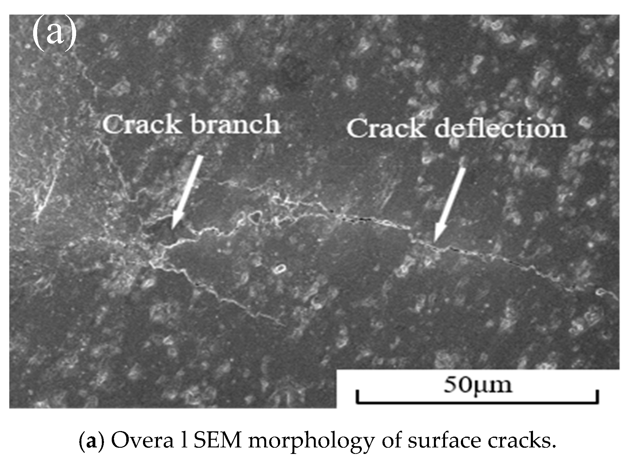
3.3. Mechanical Properties of Cermet Materials

The Ti(C,N)/Mo–Co–Ni and Ti(C,N)/Mo–Co–Ni/CaF2/Al2O3 cermet materials and coated powder addition volumes were tested according to the test methods described in the previous section. The Ti(C,N)/Mo–Co–Ni/10 vol%CaF2@Al2O3 cermet material had a content of 10%. The test results of the mechanical properties of the Ti(C,N)-based self-lubricating cermet materials are shown in Table 1. The experimental results show that the comprehensive mechanical properties of the Ti(C,N)/Mo–Co–Ni/10 vol%CaF2@Al2O3 cermet materials were the best. The hardness was 23.93 GPa, the fracture toughness was 9.94 MPa·m1/2, and the flexural strength was 997 MPa. Compared with the non-added CaF2@Al2O3 coated powder, the hardness and fracture toughness of the Ti(C,N)-based self-lubricating cermet materials increased by 24.25% and 31.83%, respectively. Compared with the direct addition of nano-CaF2 and nano-Al2O3, the hardness and fracture toughness of the Ti(C,N)-based self-lubricating cermet materials increased by 24.31% and 22.56%, respectively. The formation of a multilayer core–shell microstructure was the main reason for the improvement of the mechanical properties.
In future studies, the effect of the content of the CaF2@Al2O3 coated powder on the mechanical properties of Ti(C,N)-based cermet materials needs further experimental verification, and the formation mechanism of the multilayer core–shell microstructure needs more in-depth research.

4. Conclusions

(1) An advanced cermet material with a multilayer core–shell microstructure was successfully prepared using a vacuum hot-pressing sintering process. Compared with the general Ti(C,N)–Mo–Co–Ni cermet materials, the fracture toughness and hardness of the Ti(C,N)/Mo–Co–Ni/10 vol%CaF2@Al2O3 cermet materials are improved by 31.83% and 24.25%, respectively. A multilayer core–shell microstructure with nano-CaF2 as the core, Al2O3 as the intermediate layer, and a metal phase as the shell is formed.
(2) The formation of a multi-layer core–shell microstructure can effectively improve the mechanical properties of Ti(C,N)–Mo–Co–Ni cermet. The fracture mode of the material is the wear-through/inter-grain hybrid fracture, and the toughening mode is the crack deflection, crack bridging, and crack branching.

Author Contributions

Writing (original draft preparation), C.L.; writing (review and editing), M.Y., G.W., and C.X.

Funding

This work was supported by the National Natural Science Foundation of China (grant number 51905285,51575285), the Natural Science Foundation of Shandong Province (grant number ZR2016EEP15), the Research and Development Plan of Higher Education of Shandong Province (grant number J16LB03), the Key Research Project of Shandong Province (grant number 2017GGX30136), and the Project for the Innovation Team of Universities and Institutes in Jinan (2018GXRC005).

Acknowledgments

The authors thank all the anonymous reviewers for helping improve this paper.

Conflicts of Interest

The authors declare no conflict of interest.

References

  1. Li, Q.; Liu, N.; Liu, A.; Zhang, H. Effects of NiTi additions on the microstructure and mechanical properties of Ti(C,N)-based cermets. Int. J. Refract. Met. Hard Mater. 2013, 40, 43–50. [Google Scholar] [CrossRef]
  2. Manoj Kumar, B.V.; Balasubramaniam, R.; Basu, B. Electrochemical behavior of TiCN–Ni-based cermets. J. Am. Ceram. Soc. 2007, 90, 205–210. [Google Scholar]
  3. Wang, Y.; Zou, B.; Huang, C. Tool wear mechanisms and micro-channels quality in micro-machining of Ti-6Al-4V alloy using the Ti(C7N3)-based cermet micro-mills. Tribol. Int. 2019, 134, 60–76. [Google Scholar] [CrossRef]
  4. Wang, Y.; Zou, B.; Huang, C. Feasibility study of the Ti (C7N3)-based cermet micro-mill based on dynamic fatigue behavior and modeling of the contact stress distribution on the round cutting edge. Int. J. Mech. Sci. 2019, 155, 143–158. [Google Scholar] [CrossRef]
  5. Hao, Y.; Zou, B.; Wang, J. Effects of sintering temperature and nano Ti(C,N) on the microstructure and mechanical properties of Ti(C,N) cermets cutting tool materials with low Ni-Co. Mater. Sci. Eng. 2017, 705, 98–104. [Google Scholar]
  6. Xiang, J.; Xie, Z.; Huang, Y. Synthesis of Ti(C,N) ultrafine powders by carbothermal reduction of TiO2 derived from sol-gel process. J. Eur. Ceram. Soc. 2000, 20, 933–938. [Google Scholar] [CrossRef]
  7. Monteverde, F.; Medri, V.; Bellosi, A. Microstructure of hot-pressed Ti(C,N)-based cermet. J. Eur. Ceram. Soc. 2002, 22, 2587–2593. [Google Scholar] [CrossRef]
  8. Qu, J.; Xiong, W.; Ye, D. Effect of WC content on the microstructure and mechanical properties of Ti(C0.5N0.5)–WC–Mo–Ni cermets. Inter. J. Refract. Metal. Mater. 2010, 28, 243–249. [Google Scholar] [CrossRef]
  9. Deng, Y.; Jiang, X.Q.; Zhang, Y.H. The effect of Co particle structures on the mechanical properties and microstructure of TiCN-based cermets. Mater. Sci. Eng. A 2016, 675, 164–170. [Google Scholar] [CrossRef]
  10. Wu, P.; Liu, S.C.; Jiang, X.R. Effect of the Ratio of Co to Ni+Co on the Microstructures and Mechanical Properties of Ti(C,N)-Based Cermets. Key Eng. Mater. 2017, 726, 292–296. [Google Scholar] [CrossRef]
  11. Xu, Q.; Xing, A.; Zhao, J. Effects of metal binder on the microstructure and mechanical properties of Ti(C,N)-based cermets. J. Alloy Comp. 2015, 644, 663–672. [Google Scholar] [CrossRef]
  12. Zhang, M.; Sun, X.; Xiu, Z. Influences of sintering temperature on chemical reaction and microstructure in Al2O3-Ti(C0.7N0.3)-cBN composite. J. Nanoelect. Optoelec. 2017, 12, 701–705. [Google Scholar] [CrossRef]
  13. Zhang, M.; Li, X. Fabrication of a novel Al2O3-Ti(C0.7N0.3)-cBN composite with excellent performance in the turning of difficult-to-machine stellite alloys. Ceram. Int. 2018, 44, 12815–12824. [Google Scholar] [CrossRef]
  14. Guo, G.; Yu, J.; Luo, Z.; Qian, Z.; Tu, M. Effect of rutile titanium dioxide nano-particles and hindered amine light stabilizer on the ageing resistant properties of abs. Acta Polyme. Sinica. 2008, 8, 733–739. [Google Scholar] [CrossRef]
  15. Kong, L.; Zhu, S.; Bi, Q. Friction and wear behavior of self-lubricating ZrO2(Y2O3)-CaF2-Mo-graphite composite from 20 °C to 1000 °C. Ceram. Int. 2014, 40, 10787–10792. [Google Scholar] [CrossRef]
  16. Wu, G.; Xu, C.; Xiao, G. Self-lubricating ceramic cutting tool material with the addition of nickel coated CaF2 solid lubricant powders. Int. J. Refract. Met. Hard Mater. 2016, 56, 51–58. [Google Scholar] [CrossRef]
  17. Wang, H.M.; Yu, Y.L.; Li, S.Q. Microstructure and tribological properties of laser clad CaF2/Al2O3 self-lubrication wear-resistant ceramic matrix composite coatings. Appl. Laser. 2002, 47, 57–61. [Google Scholar] [CrossRef]
  18. Ni, J.X.; Chen, L.J.; Zhao, K.M. Preparation of gel-silica/ammonium polyphosphate core-shell flame retardant and properties of polyurethane composites. Polym. Adv. Technol. 2011, 22, 1824–1831. [Google Scholar] [CrossRef]
  19. Han, M.; Yin, X.; Cheng, L. Effect of core-shell microspheres as pore-forming agent on the properties of porous alumina ceramics. Mater. Design 2017, 113, 384–390. [Google Scholar] [CrossRef]
  20. Zhao, B.; Shao, G.; Fan, B. Fabrication and enhanced microwave absorption properties of Al2O3 nanoflake-coated Ni core–shell composite microspheres. Rsc Adv. 2014, 4, 57424–57429. [Google Scholar] [CrossRef]
  21. Han, C.; Jing, M.X.; Shen, X.Q. Fabrication and properties of core–shell structural nano-TiO2@Fe magnetic photocatalyst for removal of phenol waste water. Monatshefte fuer Chemie/Chem. Mon. 2016, 148, 1–6. [Google Scholar] [CrossRef]
  22. Wang, Y.; Wang, F.; Dong, Q. Core-shell expandable graphite@aluminum hydroxide as a flame-retardant for rigid polyurethane foams. Polym. Degrad. Stab. 2017, 146, 267–276. [Google Scholar] [CrossRef]
  23. Tejamaya, M.; Römer, I.; Merrifield, R.C. Stability of citrate, PVP, and PEG coated silver nanoparticles in ecotoxicology media. Environ. Sci. Technol. 2012, 46, 7011–7017. [Google Scholar]
  24. Yi, M.; Xu, C.; Chen, Z. Effect of nanosized CaF2 on mechanical properties of selflubricating ceramic material. J. Chin. Ceram. Soc. 2014, 42, 1127–1133. [Google Scholar]
  25. Li, M.; Xu, C.H.; Chen, Z.Q. Preparation and characterization of Al(OH)3 coated CaF2 composite powder. Adv. Mater. Res. 2014, 5, 1597–1601. [Google Scholar]
  26. Chen, Z.; Ji, L.; Guo, N. Mechanical properties and microstructure of Al2O3/TiC based self-lubricating ceramic tool with CaF2@Al(HO)3. Inter. J. Refract. Metals Hard Mater. 2018, 75, 50–55. [Google Scholar] [CrossRef]
Figure 1. TEM photographs of nano-CaF2.
Materials 12 03981 g001
Figure 2. TEM photographs of CaF2@Al(OH)3.
Materials 12 03981 g002
Figure 3. (a) SEM photographs of nano-CaF2, (b) energy dispersive spectrometer (EDS) spectra of nano-CaF2.
Materials 12 03981 g003
Figure 4. (a) SEM photographs of the CaF2@Al2O3 coated powder and (b) EDS spectra of CaF2@Al2O3 coated powder sintered at 1000 °C.
Materials 12 03981 g004
Figure 5. XRD patterns of powders: (a) CaF2, (b) CaF2@Al2O3 calcined at 80 °C, (c) CaF2@Al2O3 calcined at 800 °C, and (d) CaF2@Al2O3 calcined at 1000 °C.
Materials 12 03981 g005
Figure 6. SEM photographs of cermet, (a) SEM photographs of titanium carbonitride (Ti(C,N))/Mo–Co–Ni cermet; (b) SEM photographs of Ti(C,N)/Mo–Co–Ni/10 vol %CaF2@Al2O3 cermet.; (c) SEM photographs of Ti(C,N)/Mo–Co–Ni/CaF2/Al2O3 cermet.
Materials 12 03981 g006
Figure 7. HRTEM photographs of Ti(C,N)/Mo–Co–Ni/10 vol%CaF2@Al2O3 cermet (a) HRTEM image of Ti(C,N)/Mo–Co–Ni/10 vol%CaF2@Al2O3 cermet; (b) HRTEM image of CaF2; (c) Diffraction pattern of CaF2.
Materials 12 03981 g007
Figure 8. SEM photographs of Ti(C,N)/Mo–Co-Ni/10vol%CaF2@Al2O3 cermet surface cracks, (a) Overall SEM morphology of surface cracks; (b) SEM morphology of surface cracks enlarge.
Materials 12 03981 g008aMaterials 12 03981 g008b
Table 1. Mechanical properties of cermet materials.
ComponentFlexure Strength /MPaFracture Toughness /MPa·m1/2Hardness /GPaRelative Density /%
Ti(C,N)/Mo–Co–Ni1055 ± 277.54 ± 0.1419.26 ± 0.2298.87 ± 0.032
Ti(C,N)/Mo–Co–Ni/CaF2/Al2O31016 ± 208.11 ± 0.1219.25 ± 0.1398.89 ± 0.033
Ti(C,N)/Mo–Co–Ni/10 vol%CaF2@Al2O3997 ± 219.94 ± 0.2323.93 ± 0.2199.43 ± 0.021

