Article

Microstructure and Formation Mechanism of Ultrasound-Assisted Transient Liquid Phase Bonded Magnesium Alloys with Ni Interlayer

1
School of Mechanical and Automotive Engineering, Qingdao University of Technology, Qingdao 266000, China
2
Welding Engineering Program, The Ohio State University, Columbus, OH 43221, USA
*
Author to whom correspondence should be addressed.
Materials 2019, 12(22), 3732; https://doi.org/10.3390/ma12223732
Submission received: 9 October 2019 / Revised: 5 November 2019 / Accepted: 10 November 2019 / Published: 12 November 2019

Abstract

:
Ultrasound-assisted transient liquid phase bonding (U-TLP) has been regarded as a promising brazing process to join magnesium alloys with a Sn and Zn interlayer; however, the formation of brittle magnesium intermetallic compounds (Mg2Sn, MgZn, and MgZn2) compromises the mechanical properties of the joints. In this study, Mg alloy U-TLP joints with a Ni interlayer were evaluated based on shear strength and hardness measurement. Microstructural evolution along with ultrasonic duration time and intermetallic compound formation were characterized using X-ray diffraction and electron microscopy methods. The results show that incremental ultrasonic durations of up to 30 s lead to the microstructural evolution from the Mg2Ni layer, eutectic compounds (Mg2Ni and α-Mg) to α-Mg (Ni), accompanied by shear strength increases. The maximum value of the shear strength is 107 MPa. The role that ultrasound vibration played in brazing was evaluated, and showed that the MgO film was broken by the acoustic softening effect when the interlayer and base metal were solid. As the MgO and Mg substrate have different stress reduction τ, this plastic mismatch helps to break the oxide film. Additionally, the diffusion between the solid Mg substrate and Ni interlayer is accelerated greatly by the acoustic pressure based on the DICTRA dynamic calculation.

Graphical Abstract

1. Introduction

Magnesium and its alloys are potential candidates to replace steel and aluminum alloys in manufacturing industries in future, due to some of their unique properties like a low density, high strength-to-weight ratio, good castability, and high damping capacity [1,2]. Currently, various methods have been applied for welding magnesium alloys such as arc welding [3,4], laser welding [5,6], brazing [7], friction stir welding [8,9], and transient liquid phase bonding [10]. However, each method has its own limitation [11,12,13], such as the low penetration with arc welding, serious pore defect with laser welding, brittle intermetallic compounds (IMCs) formed with brazing, and difficulty of joining complicated structures with friction stir welding.
Ultrasound-assisted transient liquid phase bonding (U-TLP), which has been developed from the TLP method, is a low-cost, high-efficiency, green, and reliable joining method, which has been applied to join different kinds of alloys [14,15] or dissimilar alloys [16,17,18]. Xu et al. joined the Mg alloy within 1 s using a Zn layer via U-TLP; however, the joint was filled with MgZn and MgZn2, which led to a 42 MPa shear strength [19]. Lai et al. had to prolong the ultrasonic treatment time to 120 s in order to obtain a shear strength of 106 MPa, as the joint was mainly composed of α-Mg (Zn) [20]. Wang et al. adopted Ag-28Cu foil to join Mg alloys and the maximum shear strength was 92 MPa [21].
In this work, pure nickel foil was utilized to braze the Mg–Mn–Ce alloy within 30 s via U-TLP in air to get a high mechanical performance and non-defect joints as Mg–Ni intermetallic compounds (IMCs) have lower formation enthalpy and Gibbus energy, and the Ni foil has better oxidation and corrosion resistance compared with Zn, Al, and Sn foil [22,23,24]. The influence of the ultrasonic treatment time on variation of the microstructure of the brazing seam was studied. Then the mechanical performance of the joints was measured. In particular, the role that ultrasound vibration (USV) played during the U-TLP bonding was discussed in detail.

2. Experimental

The base metal (BM) used in this work was Mg–Mn–Ce alloy (1.3–2.2 wt % Mn, 0.15–0.35 wt % Ce, 0.2 wt % Al, 0.3 wt % Zn), which was provided by Northeast light alloy Co. Ltd. (Harbin, China). The BMs were cut into 20 × 20 × 3 mm3 sections. The pure Ni interlayer, which was 50 μm thick, was cut into 20 × 20 mm2 pieces. All of the BMs were sanded by SiC papers to 800 grit finish to keep the surface roughness as 12.5 μm, which helps to remove the oxide film during ultrasonic vibration. The BMs and Ni foils were cleaned by acetone using absorbent cotton and then ultrasonically cleaned in alcohol for 10 min. The schematic of the U-TLP apparatus and the arrangement of the sample are shown in Figure 1. The samples were heated by a medium frequency induction heating device with a 3 °C/s heating rate. The experiments were conducted in air with 0.15 MPa preload pressure. When heated to 520 °C, the samples were separately treated with ultrasonic vibration for 10 s, 15 s, 20 s, 25 s, 27 s, and 30 s. Then the ultrasonic vibration and heating were shut down and the samples were cooled down at the rate of 50 °C/min. The sonotrode was moved away and then the preload pressure was removed when the temperature of the samples decreased blow 200 °C.
The microstructure of the joints was characterized by a scanning electron microscope (SEM, MERLIN Compact, Qingdao, China) coupled with an energy dispersive x-ray spectrometer (EDS). To ensure reliable strength results, three samples with a length and width of 20 × 10 mm for each ultrasonic treatment time were prepared for tensile tests. The shear strength was measured by an electromechanical test machine (WDW-50KN) with a loading speed of 0.1 mm/s. The fracture surfaces were characterized using x-ray diffraction (XRD, D/max 2200VPC) with Cukα radiation to identify eutectic phases. The tube voltage and current were 40 kV and 40 mA, respectively.
The nano-hardness at the interface was measured by a nanoindentation instrument (MTS) with a testing depth of 500 nm and a dwelling time of 10 s. The Vickers hardness of the brazing seam was measured by an HXD-1000TM machine with an indentation load of 10 g and a holding time of 10 s.

3. Results

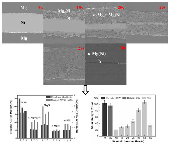
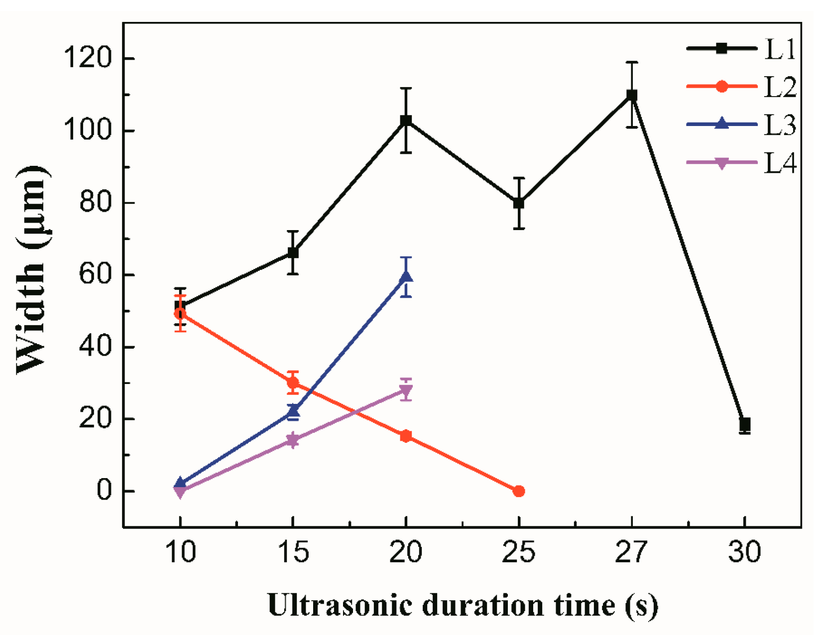
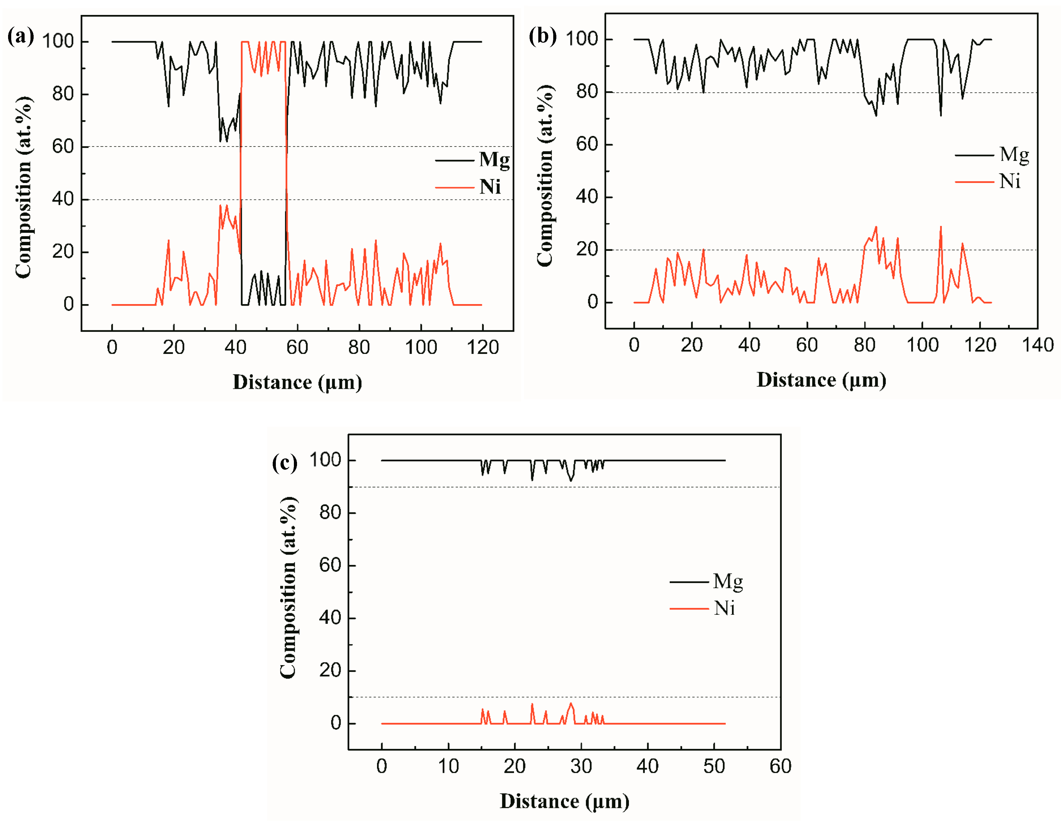
3.1. The Microstructure of Mg/Ni/Mg Joints

Figure 2 shows the microstructural changes of the joints with increasing ultrasonic treatment time and the joints clearly show three zones: a total reaction zone (L1); the remaining Ni interlayer zone (L2), and the diffusion and dissolution zone (L3 and L4). The EDS analysis of different regions in the joints is listed in Table 1. It can be seen from Figure 2a that a continuously distributed grey layer was formed at the interface between the Ni interlayer and the Mg BM with 10 s ultrasonic duration time. The EDS analysis showed that this layer (point A) was identified as Mg2Ni. The width of L3 (Mg2Ni layer) and L1 were 2.3 μm and 51.3 μm, respectively. The formation of the Mg2Ni means that the oxide film on the surface of the Mg was eliminated by USV within 10 s [18,20,25]. It was said in [14] that due to the acoustic plasticity effects, the BM and the oxide film were triggered in varying deformation and this plastic mismatch between the BM and the oxide film led to the breakage of the oxide film. So, the mutual diffusion between the Mg BM and the Ni interlayer proceeded and the Mg2Ni IMC layer was created after the fresh Mg and Ni atoms came into contact with each other.
At 15 s ultrasonic treatment time, the large blocky grey Mg2Ni (point B) and dark α-Mg were formed in L3 and L4. This is because the eutectic reaction, Equation (1), occurs at the interface
L   506   ° C   Mg 2 Ni   +   α - Mg ( Ni ) .
The width of L2 decreased to 37.8 μm and L1 increased to 66.2 μm. When the ultrasonic treatment time was 20 s, a large amount of the Ni interlayer was dissolved as the eutectic reaction proceeded. The width of L2 declined to 15.3 μm, while the width of L3 was up to 102.9 μm. When the ultrasonic treatment time was 27 s, the Ni interlayer was totally dissolved, L1 reached the maximum width value of 110.0 μm, and the joints were composed of the (Mg2Ni + α-Mg(Ni)) eutectic. Due to the intervention of the ultrasound field in this period [26,27], the dissolution and diffusion between the BM and the interlayer became faster, and the 50 μm thick Ni interlayer dissolved completely within 27 s.
When the ultrasonic time extended to 30 s, it can be seen that the width of L1 dropped sharply to 18.1 μm. The joints mainly consisted of α-Mg(Ni) solid solutions with a small amount of the (Mg2Ni + α-Mg) eutectic. In this period from 27 s to 30 s, the synergy of the USV and sonotrode pressure accelerated the process of the liquid eutectic extrusion at the joint interface.
Figure 3 shows the variation of width of zones L1–L4. It can be seen that L3 was wider than L4. This is mainly because the ultrasonic horn was placed on the L3 side of the BM and the ultrasonic wave had the characteristic that it can be attenuated in solid and liquid phase [28,29,30]. The L3 zone received USV that transferred across the solid BM while the L4 zone received USV that transferred across the solid BM, liquids in L3, and solid Ni interlayer, which meant that more energy from the USV is dissipated in the L3 zone than the L4 zone. Therefore, the degree of dissolution and diffusion in the L3 zone was higher than that in the L4 zone.
Figure 4 shows the Mg and Ni atom distribution along lines in the joints with 20 s, 27 s, and 30 s ultrasonic treatment time. It shows that the content of Ni atoms in the 20 s joint was between 20–40 at % and its distribution width was around 102.9 μm; the content of Ni atoms in the 27 s joint reduced to less than 20 at % and its distribution width increased to 110.0 μm; the content of Ni atoms in the 30 s joint was less than 10 at % and its distribution width decreased to 18.1 μm. This distribution of Ni and Mg atoms indicates that USV promoted the dissolution and diffusion between the BM and the interlayer, which lead to the composition of the joints becoming homogenous with the extension of ultrasonic treatment time.

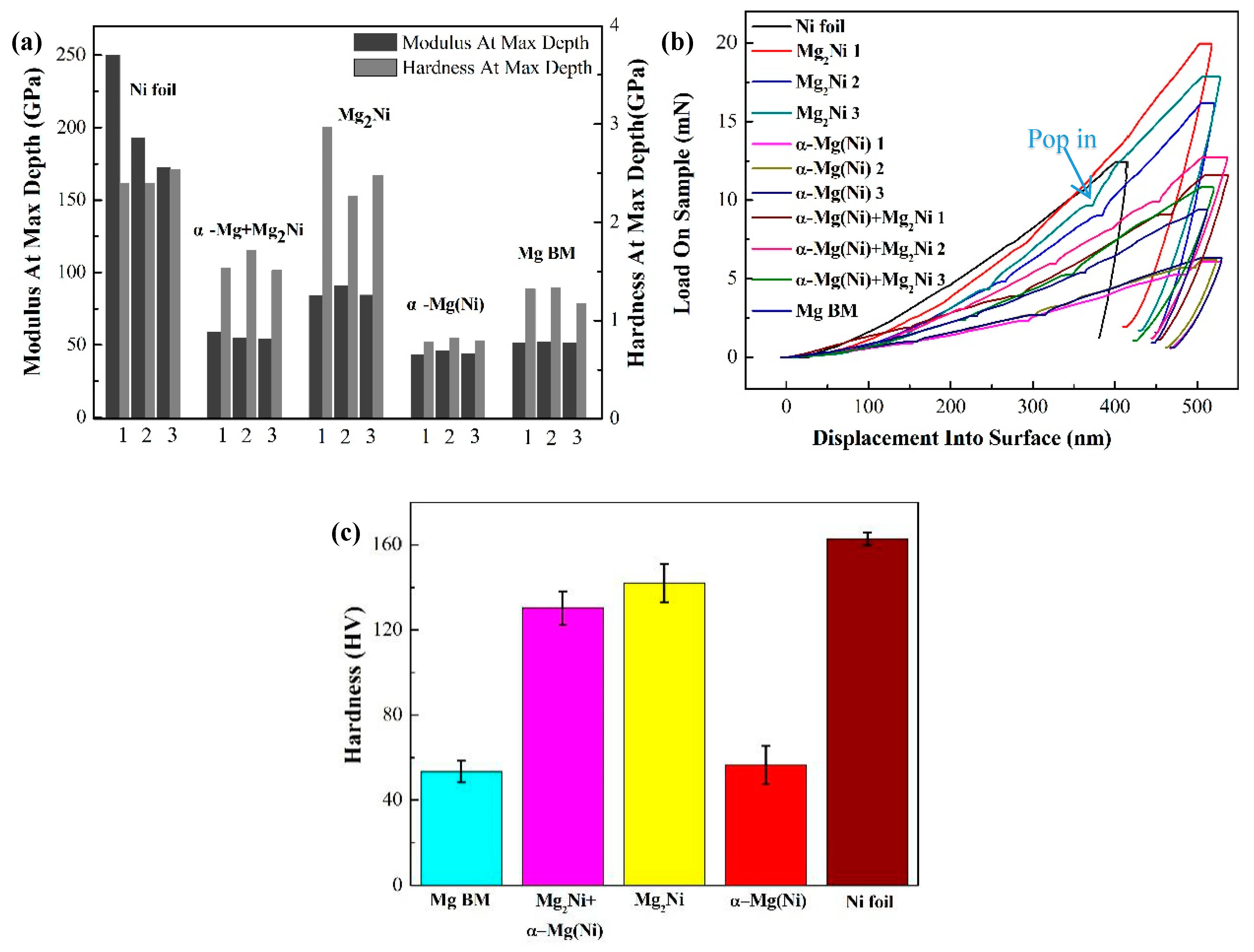
3.2. Mechanical Performance of the Mg/Ni/Mg Joints

Figure 5 shows the change of the shear strength of the BM and the joints under the incremental ultrasonic treatment time. Mg–Mn–Ce alloy is a kind of wrought magnesium alloy and it can be seen that some α-Mn particles precipitate along the grain side of α-Mg in the BM in as-received condition, while these precipitates were dissolved in the matrix after heating and USV [31,32]. The shear strength of the as-received BM was 105 MPa. The shear strength of the BM declined to 96 MPa after heating to 520 °C and 30 s of USV, which is 8.6% below the strength of the as-received BM. This reduction of shear strength is the result of the reinforced phase reduction and the ultrasonic softening caused by a hybrid field of thermal and USV [33,34,35].
As shown in Figure 5, with the increasing ultrasonic treatment time, the shear strength increased because of the ultrasonic softening and acoustic steaming effects. These two effects help to eliminate the oxide film on the BM and accelerate diffusion and dissolution between the BM and the Ni interlayer. However, prolonged ultrasonic treatment time up to 35 s induced the formation of unfilled zones caused by excess extrusion of reaction products, decreasing the shear strength of the joint. When the ultrasonic duration time was 10 s, the average shear strength of the joints was 19 MPa shown in Figure 6, which means that the oxide film was broken, and the bonding was able to form at the interface as the Mg2Ni layer was generated here (Figure 2a). When the ultrasonic treatment time was 20 s, the shear strength increased to 32 MPa. From Figure 7a it can be seen that the fracture originated in the Mg2Ni layer rather than the (Mg2Ni + α-Mg) eutectic and propagated along the interface between the Mg2Ni layer and the eutectic. According to the results of the Vickers hardness and nanoindentation hardness of the phase shown in Figure 6, the Vicker Hardness (HV) hardness of Mg2Ni was 142.0 HV and the nano-hardness of it ranged from 2.265 to 2.969 GPa; whereas the HV hardness of the eutectic was 130.2 HV and the nano-hardness of it ranged from 1.511 to 1.714 GPa. In other words, the Mg2Ni layer is harder than the (Mg2Ni + α-Mg) eutectic, which means that the Mg2Ni layer formed at the surface of Ni foil is the most brittle area in the joint. These harder regions are prone to be the crack initiation spot, which can be confirmed by the x-ray diffraction analysis of the fracture surfaces. Additionally, the pop-in events occurred in load–displacement curves shown in Figure 6b, which means that the phases underwent an elastic–plastic transition and then micro-deformations were induced [36,37].
After 27 s ultrasonic treatment, the Ni interlayer was dissolved completely and the joint was only composed of the Mg2Ni+α-Mg(Ni) eutectic, which meant that the shear strength increased to 80 MPa. It can be seen that the fracture path originated and propagated along the eutectic in Figure 7b. Without the existence of a continuous, distributed, brittle, Mg2Ni layer, the fracture path will be blocked by the α-Mg in the eutectic to some extent, which leads to the improvement of shear strength.
When ultrasonic time extended to 30 s, the joint was mainly composed of α-Mg(Ni) solutions and the shear strength reached its maximum value of 107 MPa, which is 102% of the as-received BM and 111% of the BM after heating and ultrasonic treating. This is mainly because the abundant brittle Mg2Ni IMCs were squeezed out and α-Mg (Ni) remained in the joint, with a Vickers hardness of 56.4 HV and nano-hardness ranging from 0.784 to 0.821 GPa. There were two fracture paths formed at this joint, shown in Figure 7c. One was located in the brazing seam, the other was at the Mg BM. The nano-hardness and Vickers hardness of this phase in the Mg BM were close to those of α-Mg (Ni), which means that the origin of the crack will occur randomly in either the brazing seam or the Mg BM when the joints are subjected to the same shear force. From Figure 2f it can be seen that a small amount of the eutectic still existed in the seam. As the shear force continued to increase, the fracture was propagated more quickly along the eutectic in the brazing seam than in the BM. Therefore, the joint was finally broken at the brazing seam. The fracture morphology of the 30 s joint shown in Figure 7d belonged to a typical brittle fracture feature. The large, flat α-Mg and small, fragmentized Mg2Ni were observed there. Jin et al. studied the joints using an Ni interlayer via TLP [38]. The samples were heated to 515 °C and kept at that temperature for 60 min, and the shear strength of them was 36 MPa. The main reason for this relatively low shear strength was that a large amount of the Mg2Ni existed in the brazing seam. With the U-TLP method, the brittle Mg2Ni IMCs were squeezed out and the joint was mainly composed of α-Mg [20,21].
When ultrasonic treatment time was 35 s, the shear strength dropped sharply and some defects like unfilled zones were generated in the brazing seam. The main reason was that the excessive reactive products were squeezed out under the action of the acoustic steaming effect.
Figure 8 shows the XRD patterns taken from the fracture surface of the joints with 20 s and 30 s ultrasonic treatment time. It shows that from the fracture surface of the 20 s joint the Ni had more intensive XRD pattern. This means that the fracture was located near the unreacted Ni interlayer, which was the place that the Mg2Ni layer was concentrated. In the fracture surface of the 30 s sample, the phases consisted of α-Mg and Mg2Ni. All of these results were consistent with those of the SEM and shear strength test.

4. Discussion

The joint formation process in this work is shown in Figure 9. Figure 9a shows the sample before ultrasonic treatment. MgO layers are formed on the Mg BM as the BM was heated in air. After the USV is turned on, the MgO layers are broken rapidly, as shown in Figure 9b. This breakdown of the oxide layer results from the plasticity mismatch between the oxide layers and the Mg BM, which is caused by the acoustic softening effect [34,35]. Acoustic softening is the reduction in apparent static stress necessary for plastic deformation in a material under the influence of ultrasonic energy. Sayed et al. pointed out that the reduction of stress by acoustic softening was considered to be proportional to the acoustic intensity [39,40]. While Huang et al. discovered that the stress reduction was proportional to the vibration amplitude [41]. A model of the acoustic softening effect based on the thermal activation theory was cited by Yao et al. [42,43]. It is reported that applying high-frequency vibration during the plastic deformation leads to a stress reduction, which is called the ultrasonic volume effect [35]. The stress reduction τ can be expressed as Equation (2) [44,45]
τ = τ ^ [ 1 k T ln ( γ 0 ˙ / γ p ˙ ) / Δ F , ]
where k is the Boltzmann constant; T is the Kelvin temperature; γ 0 ˙ is the pre-exponential factor, which is a constant between −1 and 1 and is obtained by the experiment;   γ p ˙ is the shear plastic strain rate obtained by the experiment; Δ F is the activation energy required to overcome the obstacle without the help from external stress. τ ^ is the mechanical threshold, which is usually expressed as Equation (3) [46]
τ ^ = τ 0 + μ α b ρ ,
where τ 0 is the friction stress; μ is the elastic shear modulus; α is a coefficient close to 1 / 3 ; b is the length of the Burgers vector; p is the dislocation density. Replacing   k T ln ( γ 0 ˙ / γ p ˙ ) / Δ F with W, Equation (2) changes to Equation (4)
τ = τ ^ ( 1 W ) .
Therefore, in addition to the acoustic intensity and vibration amplitude, the stress reduction τ also depends on some physical properties of the materials such as τ 0 , μ, Δ F , and b, which are listed in Table 2. Based on the stress-reduction equation, the difference of the acoustic softening effect during the USV process between the Mg alloy and its oxide layer will lead to their plasticity mismatch, which eventually causes the breakdown of the surface oxide layer.
After the MgO layer was broken in some areas, the fresh Mg and Ni atoms come to contact with each other and the Mg2Ni IMC layer generated by mutual diffusion is formed at the surface of the Ni interlayer within 10 s ultrasonic duration time, which is shown in Figure 9c. It took 5 min to form this solid-state diffusion layer at 515 °C using TLP bonding for an AZ31/Ni/AZ31 joint [38]. So, it can be concluded that the diffusion time between the Ni interlayer and the Mg BM is greatly shortened by the ultrasonic treatment. This is mainly due to the fact that the acoustic pressure affects the mobility, the diffusion potential, and the boundary conditions for diffusion [55,56,57]. The stress as a driving force for diffusion in formation of solute-atom atmosphere around dislocations was studied [58]. In a system containing a stress field, a diffusing particle generally experiences a force in a direction that reduces its interaction energy with the stress field. To find the driving force exerted on an interstitial solute atom by the stress field, the entropy production must be considered. In a small cell embedded in the material, the energy caused by stress-induced diffusion is presented as Equation (5)
d w = P Δ Ω 1 d c 1 ,
where Δ Ω 1 is a pure dilation caused by the interstitial space; P is pressure; c 1 is the concentration of atoms. For the isotropic elastic material, P = σ x x + σ y y + σ z z 3 . The total driving force, including chemical potential, can be represented as Equation (6)
F 1 = ( μ 1 + Δ Ω 1 P ) .
The diffusion potential is an ‘elastochemical’ type of potential corresponding to Equation (7)
Φ 1 = μ 1 + Δ Ω 1 P .
Therefore, the entropy flux is Equation (8)
J 1 = L 11 F 1 = L 11 Φ 1 = D 1 ( c 1 + c 1 Δ Ω 1 k T P ) ,
where L11 is the Onsager coupling coefficient that can be calculated by introducing diffusivity D1.
Based on Equations (5)–(8), the relationship between the entropy flux J 1 and driving force   F 1 has been revealed qualitatively, which indicates that the entropy flux to overcome the block of dilation decreases and the atom diffusion in solids will be accelerated with the additional driving force from ultrasonic vibration.
So far, it can be seen that stress induces and influences diffusion directly. The quantitative analysis on mutual diffusion between Ni foil and Mg BMs with USV was conducted through DICTRA software (Pittsburgh, PA, USA). The pressure of TLP bonding in an AZ31/Ni/AZ31 joint is 0.0053 Pa [38], whereas in Liu’s research, the maximum pressure on the Al substrate is 6.08 × 10⁵ Pa with USV [59], which indicates that the pressure with USV is about 108 times of that without USV. This intensified pressure was converted to an enhancement factor to apply in the simulation model. Figure 10 shows the simulation model and results of the mutual diffusion between the Ni foil and the Mg BM with, or without, USV from the DICTRA software. The temperature of this diffusion simulation is 520 °C. As the Mg2Ni IMC layer is formed at the interface between the Ni foil and the Mg BM, it is assumed that the concentration of Mg atoms is 0 at % along the centerline of the Ni foil and 0.67 at % at the reaction interface of the Ni foil side, meanwhile, the concentration of Ni atoms is 0at % at 200 μm away from the reaction interface in the Mg BM and 0.33 at % at the reaction interface of the Mg BM side. This composition boundary condition is shown in Figure 10a. It can be seen in Figure 10b,c that the diffusion distance of Ni atoms in the Mg BM is longer than that of Mg atoms in the Ni foil, which means that the Mg BM is consumed faster than the Ni foil, and the reaction interface mainly moves toward to the Mg BM side. Comparing atom concentration with and without USV, the concentration distribution of solute atoms are more uneven with USV than without USV. It can be seen in Figure 10c that the Ni composition in the Mg BM is inclined to increase and concentrate in some areas with increasing USV duration. That is, the diffusion distance of Ni atoms in the Mg BM that reach 0.33 at % is 14 μm when heated for 5 s without USV, whereas the diffusion distance of Ni atoms that reach 0.33 at % is 27 μm when heated for 5 s with USV. The diffusion distance of Ni atoms that reach 0.33 at % is 43 μm when heated for 30 s without USV, whereas the diffusion distance of Ni atoms that reach 0.33 at % is 136 μm when heated for 30 s with USV. Therefore, it can be concluded that the diffusion between the Mg BM and the Ni foil is accelerated by the introduction of USV.
With the continuity of mutual diffusion and dissolution, the liquid eutectic phases composed of α-Mg and Mg2Ni will be generated, as shown in Figure 9d. Once the liquid phase is formed, the cavitation effect will lift the MgO layer, which is called undermining [60]. As the cavitation threshold of the liquids is 0.3–0.6 × 10⁵ Pa, which is much lower than the acoustic pressure caused by USV, a large number of cavitation bubbles are generated in the eutectic and the MgO layers are effectively removed by these bubbles [61]. In addition, due to the numerous bubbles that are ceaselessly formed and collapsed, the dissolution activation energy is decreased and the dissolution rate at the interface is accelerated remarkably [59,62]. Therefore, both the diffusion and the dissolution between the Ni foil and the Mg BM can be accelerated by USV and the Ni foil will be consumed within 27 s, which is shown in Figure 9e.
In the period of 29–30 s ultrasonic treatment time, shown in Figure 9f, the width of the eutectic declines dramatically due to the acoustic steaming effect of USV. The flowing rate of the eutectic is accelerated and then a mass of eutectic is squeezed out [19,20,21]. The remaining structure is mainly composed of α-Mg (Ni). In other words, the reason for the increase of the shear strength to 107 MPa is that the brittle structure of the eutectic composed of Mg2Ni+α-Mg is squeezed out of the joints by the acoustic steaming effect, and the plastic and ductile structure of α-Mg (Ni) remains.
By far, the role that USV played in TLP bonding of Mg/Ni/Mg joints is summed up as follows. The MgO film on the Mg BM is broken by the acoustic softening effect and removed by undermining from the cavitation effect; the solid-state diffusion between the Ni foil and the Mg BM is accelerated by acoustic pressure, and the dissolution between the Ni foil and the Mg BM is increased by the cavitation effect; the brittle eutectic is extruded by the acoustic steaming effect, which increases the shear strength of the joints.

5. Conclusions

(1) Magnesium alloys can be joined with a Ni interlayer via U-TLP within 30 s of ultrasound treatment in air.
(2) The microstructure of the joints evolved from the Mg2Ni layer, the eutectic composed of Mg2Ni and α-Mg, to the α-Mg (Ni) solid solution with the increase of ultrasound treatment time.
(3) With incremental increases in ultrasonic duration, the shear strength increased from 19 MPa to the maximum value of 107 MPa; however, it declined to 35 MPa when the ultrasonic treatment time was prolonged to 35 s. If the continuous Mg2Ni layer along the Ni interlayer existed, the fracture path was prone to be along the Mg2Ni layer as the Mg2Ni is the hardest phase in the brazing seam. When the Ni interlayer was consumed, the fracture path originated and propagated along the eutectic. When the majority of Mg2Ni was squeezed out and α-Mg(Ni) remained, the fracture paths originated and propagated either in the Mg BM or in the brazing seam as the hardness of α-Mg(Ni) is close to that of the BM.
(4) The oxide film was broken by the acoustic softening effect at the stage where the Mg BM and Ni interlayer were in a solid state. The MgO film and Mg BM undergo different degrees of stress reduction as properties such as τ0, μ, Δ F , and b of MgO and Mg are different when USV is occurring, which induces the plastic mismatch in deformation and helps to break the MgO film. The composition and diffusion distance of solute atom in matrix was increased by the acoustic pressure from USV, which helps to shorten the mutual diffusion time between the BM and the interlayer to less than 10 s.

Author Contributions

The conceptualization, software and methodology, Y.L.; validation, C.Y., Z.W. and Z.C.; review and editing, Z.P.

Funding

This project was supported by the National Natural Science Foundation of China (Grant numbers 51871128, 51875300), Natural Science Foundation of Shandong Province (Grant numbers ZR2017MEE012, ZR2018MEE017) and Key Research and Development Plan of Shandong Province (Grant number 2018GGX103036).

Conflicts of Interest

The authors declare no conflict of interest.

References

  1. Mordlike, B.L.; Ebert, T. Magnesium: Properties-applications-potential. Mater. Sci. Eng. A 2001, 301, 37–45. [Google Scholar] [CrossRef]
  2. Liu, L.M.; Ren, D.X.; Liu, F. A Review of Dissimilar Weld Techniques for Magnesium Alloys to Aluminum alloys. Materials 2014, 7, 3735–3757. [Google Scholar] [CrossRef] [PubMed]
  3. Xie, X.; Shen, J.; Cheng, L. Effects of nano-particles strengthening activating flux on the microstructures and mechanical properties of TIG welded AZ31 magnesium alloy joints. Mater. Des. 2015, 81, 31–38. [Google Scholar] [CrossRef]
  4. Wang, H.Y.; Li, N.; Liu, L.M. Investigation of the Joining Technology of FRP/AZ31B Magnesium Alloy by Welding and Riveting Hybrid Bonding Method. Materials 2019, 12, 2167. [Google Scholar] [CrossRef] [PubMed]
  5. Wahba, M.; Mizutani, M.; Kawahito, Y. Laser welding of die-cast AZ91D magnesium alloy. Mater. Des. 2012, 33, 569–576. [Google Scholar] [CrossRef]
  6. Li, T.T.; Song, G.; Zhang, Z.D. Mechanical Properties and Microstructures of Laser-TIG Welded ME21 Rare Earth Mg Alloy. Materials 2019, 12, 2188. [Google Scholar] [CrossRef] [PubMed]
  7. Wang, Z.; Qu, W.Q.; Zhuang, H.S. Development of Mg-Al filler metal for brazing magnesium alloy AZ31B. Mater. Lett. 2016, 182, 75–77. [Google Scholar] [CrossRef]
  8. Xu, N.; Song, Q.N. Mechanical properties’ modification of large load friction stir welded AZ31B Mg alloy joint. Mater. Lett. 2018, 219, 93–96. [Google Scholar] [CrossRef]
  9. Zheng, Y.; Pan, X.M.; Ma, Y.L. Microstructure and Corrosion Behavior of Friction Stir-Welded 6061 Al/AZ31 Mg Joints with a Zr Interlayer. Materials 2019, 12, 1115. [Google Scholar] [CrossRef] [PubMed]
  10. AlHazaa, A.; Alhoweml, I.; Shar, M.A. Transient Liquid Phase Bonding of Ti-6Al-4V and Mg-AZ31 Alloys Using Zn Coatings. Materials 2019, 12, 769. [Google Scholar] [CrossRef] [PubMed]
  11. Chowdhury, S.M.; Chen, D.L.; Bhole, S.D. Microstructure and mechanical properties of fiber-laser-welded and diode-laser-welded AZ31 magnesium. Metall. Mater. Trans. A 2011, 42, 1974–1989. [Google Scholar] [CrossRef]
  12. Munitz, A.; Cotler, C.; Stern, A. Mechanical properties and microstructure of gas tungsten arc welded magnesium AZ91D plates. Mater. Sci. Eng. A 2001, 302, 68–73. [Google Scholar] [CrossRef]
  13. Harooni, M.; Carlson, B.; Strohmeier, B.R. Pore formation mechanism and its mitigation in laser welding of AZ31B magnesium alloy in lap joint configuration. Mater. Des. 2014, 58, 265–276. [Google Scholar] [CrossRef]
  14. Shao, H.K.; Wu, A.P.; Bao, Y.D. Rapid Ag/Sn/Ag transient liquid phase bonding for high-temperature power devices packaging by assistance of ultrasound. Ultrason. Sonochem. 2017, 37, 561–570. [Google Scholar] [CrossRef] [PubMed]
  15. Guo, W.B.; Leng, X.S.; Luan, T.M. Ultrasonic-promoted rapid TLP bonding of fine-grained 7034 high strength aluminum alloys. Ultrason. Sonochem. 2017, 36, 354–361. [Google Scholar] [CrossRef] [PubMed]
  16. Xu, Z.W.; Li, Z.W.; Li, L.Q. Control Al/Mg intermetallic compound formation during ultrasonic-assisted soldering Mg to Al. Ultrason. Sonochem. 2018, 46, 48–88. [Google Scholar] [CrossRef] [PubMed]
  17. Lai, Z.W.; Pan, C.; Du, H.D. Ultrasonic-assisted fluxless reactive bonding of Mg/Al dissimilar alloy using Zn–Al solder in air. Sci. Technol. Weld. Join. 2018, 23, 19–27. [Google Scholar] [CrossRef]
  18. Li, Z.W.; Xu, Z.W.; Zhu, D.W. Control of Mg2Sn formation through ultrasonic-assisted transient liquid phase bonding of Mg to Al. J. Mater. Process. Technol. 2018, 255, 524–529. [Google Scholar] [CrossRef]
  19. Xu, Z.; Li, Z.; Peng, L.; Yan, J. Ultra-rapid transient liquid phase bonding of Mg alloys within 1 s in air by ultrasonic assistance. Mater. Des. 2019, 161, 72–79. [Google Scholar] [CrossRef]
  20. Lai, Z.W.; Chen, X.G.; Pan, C. Joining Mg alloys with Zn interlayer by novel ultrasonic-assisted transient liquid phase bonding method in air. Mater. Lett. 2016, 166, 219–222. [Google Scholar] [CrossRef]
  21. Wang, Q.; Fu, Y.; Liang, Q. Microstructure and mechanical properties of magnesium alloys joints with Ag-Cu interlayer by ultrasonic-induced transient liquid phase bonding in air for structure lightweight design. Mater. Lett. 2019, 237, 37–40. [Google Scholar] [CrossRef]
  22. Khodabakhshi, F.; Shah, L.H.; Gerlich, A.P. Dissimilar laser welding of an AA6022-AZ31 lap-joining by using Ni-interlayer: Novel beam-wobbing technique, processing parameters, and metallurgical characterization. Opt. Laser Technol. 2019, 112, 349–362. [Google Scholar] [CrossRef]
  23. Shah, L.H.; Gerlich, A.; Zhou, Y. Design guideline for intermetallic compound mitigation in Al-Mg dissimilar welding through addition of interlayer. Int. J. Adv. Manuf. Technol. 2018, 94, 2667–2678. [Google Scholar] [CrossRef]
  24. Wang, H.Y.; Liu, L.M.; Liu, F. The characterization investigation of laser-arc-adhesive hybrid welding of Mg to Al joint using Ni interlayer. Mater. Des. 2013, 50, 463–466. [Google Scholar] [CrossRef]
  25. Xie, R.S.; Chen, X.G.; Lai, Z.W. Microstructure, mechanical properties and mechanism of ultrasound-assisted rapid transient liquid phase bonding of magnesium alloy in air. Mater. Des. 2016, 91, 19–27. [Google Scholar] [CrossRef]
  26. Cui, W.; Wang, C.W.; Yan, J.C. Wetting and reaction promoted by ultrasound between sapphire and liquid Al-12Si alloy. Ultrason. Sonochem. 2013, 20, 196–201. [Google Scholar] [CrossRef] [PubMed]
  27. Chen, X.G.; Yan, J.C.; Ren, S.C. Microstructure and mechanical properties of Ti-6Al-4V/Al1060 joints by ultrasonic-assisted brazing in air. Mater. Lett. 2013, 95, 197–200. [Google Scholar] [CrossRef]
  28. Gu, J.; Fan, F.; Li, Y.; Yang, H.; Su, M.; Cai, X. Modeling and prediction of ultrasonic attenuation in liquid-solid dispersions containing mixed particles with Monte Carlo method. Particuology 2019, 43, 84–91. [Google Scholar] [CrossRef]
  29. Grosjean, V.; Julcour, C.; Louisnard, O.; Barthe, L. Axial acoustic field along a solid-liquid fluidized bed under power ultrasound. Ultrason. Sonochem. 2019, 56, 273–283. [Google Scholar] [CrossRef] [PubMed] [Green Version]
  30. Hutchinson, B.; Lundin, P.; Lindh-Ulmgren, E.; Lévesque, D. Anomalous ultrasonic attenuation in ferritic steels at elevated temperatures. Ultrasonics 2016, 69, 268–272. [Google Scholar] [CrossRef] [PubMed]
  31. Robson, J.D.; Henry, D.T. Particle effects on recrystallization in magnesium-manganese alloys: Particle pining. Mater. Sci. Eng. A 2011, 528, 4239–4247. [Google Scholar] [CrossRef]
  32. Wang, J.; Lu, R.; Qin, D.; Huang, X.; Pan, F. A study of the ultrahigh damping capacities in Mg-Mn alloys. Mater. Sci. Eng. A 2013, 560, 667–671. [Google Scholar] [CrossRef]
  33. Rusinko, A. Analytical description of ultrasonic hardening and softening. Ultrasonics 2011, 51, 709–714. [Google Scholar] [CrossRef] [PubMed]
  34. Kelly, G.S.; Advani, S.G.; Gillespie, J.W., Jr.; Bogetti, T.A. A model to characterize acoustic softening during ultrasonic consolidation. J. Mater. Process. Technol. 2013, 213, 1835–1845. [Google Scholar] [CrossRef]
  35. Hu, J.; Shimizu, T.; Yang, M. Investigation on ultrasonic volume effects: Stress superposition, acoustic softening and dynamic impact. Ultrason. Sonochem. 2018, 48, 240–248. [Google Scholar] [CrossRef] [PubMed]
  36. Ramamurty, U.; Jang, J. Nanoindentation for probing the mechanical behavior of molecular crystals—A review of the technique and how to use it. Cryst. Eng. Comm. 2014, 16, 12–23. [Google Scholar] [CrossRef]
  37. Wang, Y.K.; Liu, W.S.; Ma, Y.Z. Indentation depth dependent micromechanical properties and rate dependent pop-in events of (Au, Cu)5Sn. Mater. Lett. 2014, 131, 57–60. [Google Scholar] [CrossRef]
  38. Jin, Y.J.; Khan, T.I. Effect of bonding time on microstructure and mechanical properties of transient liquid phase bonded magnesium AZ31 alloy. Mater. Des. 2012, 38, 32–37. [Google Scholar] [CrossRef]
  39. Siddiq, A.; Sayed, T.E. Acoustic softening in metals during ultrasonic assisted deformation via CP-FEM. Mater. Lett. 2011, 65, 356–359. [Google Scholar] [CrossRef]
  40. Siddiq, A.; Sayed, T.E. A thermomechanical crystal plasticity constitutive model for ultrasonic consolidation. Comput. Mater. Sci. 2012, 51, 241–251. [Google Scholar] [CrossRef]
  41. Huang, H.; Pequegnat, A.; Chang, B.H. Influence of superimposed ultrasound on deformability of Cu. J. Appl. Phys. 2009, 6, 113514. [Google Scholar] [CrossRef]
  42. Yao, Z.H.; Kim, G.Y.; Wang, Z.H. Acoustic softening and residual hardening in aluminum: Modeling and experiments. Int. J. Plast. 2012, 39, 75–87. [Google Scholar] [CrossRef]
  43. Yao, Z.; Mei, D.; Chen, Z. Modeling of metallic surface topography modification by high-frequency vibration. J. Sound Vibr. 2016, 363, 258–271. [Google Scholar] [CrossRef]
  44. Frost, H.J.; Ashby, M.F. Deformation-Mechanism Maps: The Plasticity and Creep of Metals and Ceramics, Firsted; Pergamon Press: Oxford, UK, 1982. [Google Scholar]
  45. Kocks, U.F. Constitutive Behavior Based on Crystal Plasticity, Unified Constitutive Equations for Creep and Plasticity; Springer: Dordrecht, The Netherlands, 1987; pp. 1–88. [Google Scholar]
  46. Barlat, F.; Glazov, M.V.; Brem, J.C.; Lege, D.J. A simple model for dislocation behavior, strain and strain rate hardening evolution in deforming aluminum alloys. Int. J. Plast. 2002, 18, 919–939. [Google Scholar] [CrossRef]
  47. Li, Q.Z.; Jiao, X. Recrystallization mechanism and activation energies of severely-deformed magnesium during annealing process. Materialia 2019, 5, 100188. [Google Scholar] [CrossRef]
  48. Tang, X.J.; Nie, Y.X.; Jin, Q. Kinetics and mechanism of ultrasonic-assisted magnesium oxide hydration. Ultrason. Sonochem. 2018, 40, 995–1002. [Google Scholar] [CrossRef] [PubMed]
  49. Sandlöbes, S.; Friák, M.; Neugebauer, J. Basal and non-basal dislocation slip in Mg-Y. Mater. Sci. Eng. A 2013, 576, 61–68. [Google Scholar] [CrossRef]
  50. Higashida, K.; Okazaki, S.; Morikawa, T. Burgers vector of crack tip dislocation in magnesium oxide crystals. Mater. Trans. 1998, 39, 967–974. [Google Scholar] [CrossRef]
  51. Garlea, E.; Radovic, M.; Liaw, P.K. High-temperature dependency of elastic mechanical behavior of two wrought magnesium alloys AS31B and ZK60A studied by resonant ultrasound spectroscopy. Mater. Sci. Eng. A 2019, 758, 86–95. [Google Scholar] [CrossRef]
  52. Fu, X.Q.; Liang, L.H.; Wei, Y.G. Atomistic simulation study on the shear behavior of Ag/MgO interface. Comput. Mater. Sci. 2018, 155, 116–128. [Google Scholar] [CrossRef]
  53. Wang, L.; Zhao, Y.; Zhang, J.; Ma, R.; Liu, Y.; Wang, Y.; Zhang, Q.; Li, W.; Zhang, Y. Quantitative analysis on friction stress of hot-extruded AZ31magnesium alloy at room temperature. J. Mater. Sci. Technol. 2018, 34, 1765–1772. [Google Scholar] [CrossRef]
  54. Wachtman, J.B. Mechanical and Thermal Properties of Ceramics; National Bureau of Standards Special Publication: Washington, DC, USA, 1969; p. 231. [Google Scholar]
  55. Larche, F.C.; Voorhees, P.W. Diffusion and stresses, basic thermodynamics. Defect Diffus. 1996, 129, 31–36. [Google Scholar] [CrossRef]
  56. Fischer, F.D.; Svoboda, J. Deformation and diffusion interactions in solids-A simulation study. J. Mech. Phys. Solids 2015, 78, 427–442. [Google Scholar] [CrossRef]
  57. Larcht’e, F.C.; Cahn, J. The effect of self-stress on diffusion in solids. Acta Metall. 1982, 30, 1835–1845. [Google Scholar] [CrossRef]
  58. Balluffi, R.W. Kinetics of Materials; Wiley-Interscience: Hoboken, NJ, USA, 2005. [Google Scholar]
  59. Liu, Y.; Yu, W.; Liu, Y.Z. Effect of ultrasound on dissolution of Al in Sn. Ultrason. Sonochem. 2019, 50, 67–73. [Google Scholar] [CrossRef] [PubMed]
  60. Xu, Z.; Yan, J.; Zhang, B.; Kong, X.; Yang, S. Behaviors of oxide film at the ultrasonic aided interaction interface of Zn-Al alloys and Al2O3/6061Al composites in air. Mater. Sci. Eng. A 2006, 45, 80–86. [Google Scholar] [CrossRef]
  61. Tzanakis, I.; Xu, W.W.; Lebon, G.S.B.; Eskin, D.G. In Situ synchrotron radiography and spectrum analysis of transient cavitation bubbles in molten aluminum alloy. Phys. Procedia 2015, 70, 841–845. [Google Scholar] [CrossRef]
  62. Li, Z.; Xu, Z.; Ma, L.; Wang, S.; Liu, X.; Yan, J. Cavitation at filler metal/substrate interface during ultrasonic-assisted soldering. Part I: Cavitation characteristics. Ultrason. Sonochem. 2018, 49, 249–259. [Google Scholar] [CrossRef] [PubMed]
Figure 1. Schematic of ultrasound-assisted transient liquid phase bonding (U-TLP).
Materials 12 03732 g001
Figure 2. Microstructure of the joints with 10 s (a), 15 s (b), 20 s (c), 25 s (d), 27 s (e), and 30 s (f) ultrasonic treatment time.
Materials 12 03732 g002
Figure 3. The width of zones L1–L4.
Materials 12 03732 g003
Figure 4. Distribution of elements across the joints (a) along line AB; (b) along line CD; (c) along line EF.
Materials 12 03732 g004
Figure 5. The shear strength of three samples of the base metals (BMs) and the joints at the given set of parameters.
Materials 12 03732 g005
Figure 6. Nanoindentation hardness (a) hardness and modulus; (b) load–displacement curves, and (c) Vickers hardness at the microstructure.
Materials 12 03732 g006
Figure 7. The fracture path in a series of ultrasonic treatment times (a) 20 s; (b) 27 s; (c) 30 s, and (d) morphology of the joint with 30 s ultrasonic treatment time.
Materials 12 03732 g007
Figure 8. XRD analysis of fracture morphology.
Materials 12 03732 g008
Figure 9. The joint formation mechanism (a) before ultrasonic treatment, (b) 0~9 s, (c) 10 s, (d) 11~26 s, (e) 27~29 s, (f) 30 s.
Materials 12 03732 g009
Figure 10. The schematic of solid-state diffusion (a), the diffusion results in the Ni interlayer (b) and the Mg BM (c) from DICTRA software calculation.
Materials 12 03732 g010
Table 1. Chemical composition at different regions in Figure 2.
PointMg (at %)Ni (at %)Possible Phase
A68.2331.77Mg2Ni
B66.8933.11Mg2Ni
C4.1095.90Ni
D66.9233.08Mg2Ni
E98.851.15α-Mg(Ni)
F67.0432.96Mg2Ni
G97.802.20α-Mg(Ni)
H78.7621.24Mg2Ni + α-Mg(Ni)
I98.901.10α-Mg(Ni)
Table 2. Property values of Mg alloys and MgO.
ParametersMg AlloysMgO
ΔF (kJ/mol)24.2 [47]22.5 [48]
b (nm) 1 / 3 1   1   2 ¯   3 [49] 1 / 2 1   1   0 ¯ [50]
μ (GPa)31.2 [51]16.1 [52]
τ 0 (MPa)30~145 [53]40~55 [54]

