The Influence of Post Weld Heat Treatment Precipitation on Duplex Stainless Steels Weld Overlay towards Pitting Corrosion

 ,
, 

Abstract
:1. Introduction
2. Materials and Methods
2.1. Ferrite Prediction and Measurement
2.2. Process Parameter
2.3. Heat Treatment
2.4. Pitting Corrosion Resistance
2.5. Volume Fraction Determination
3. Results and Discussion
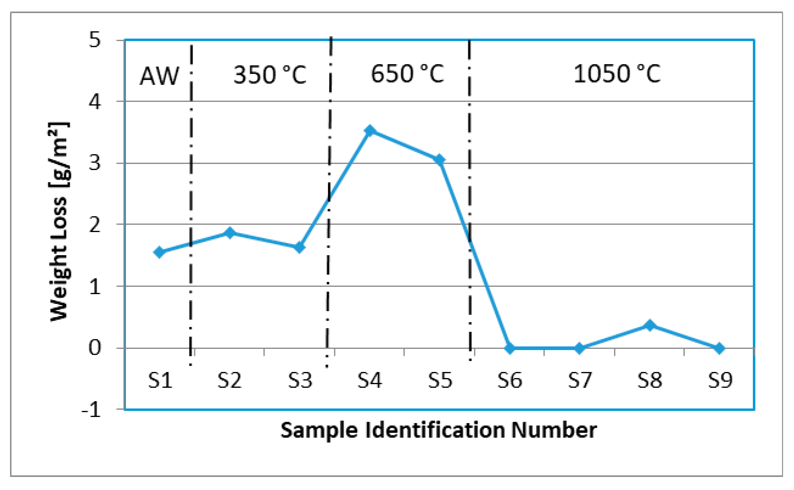
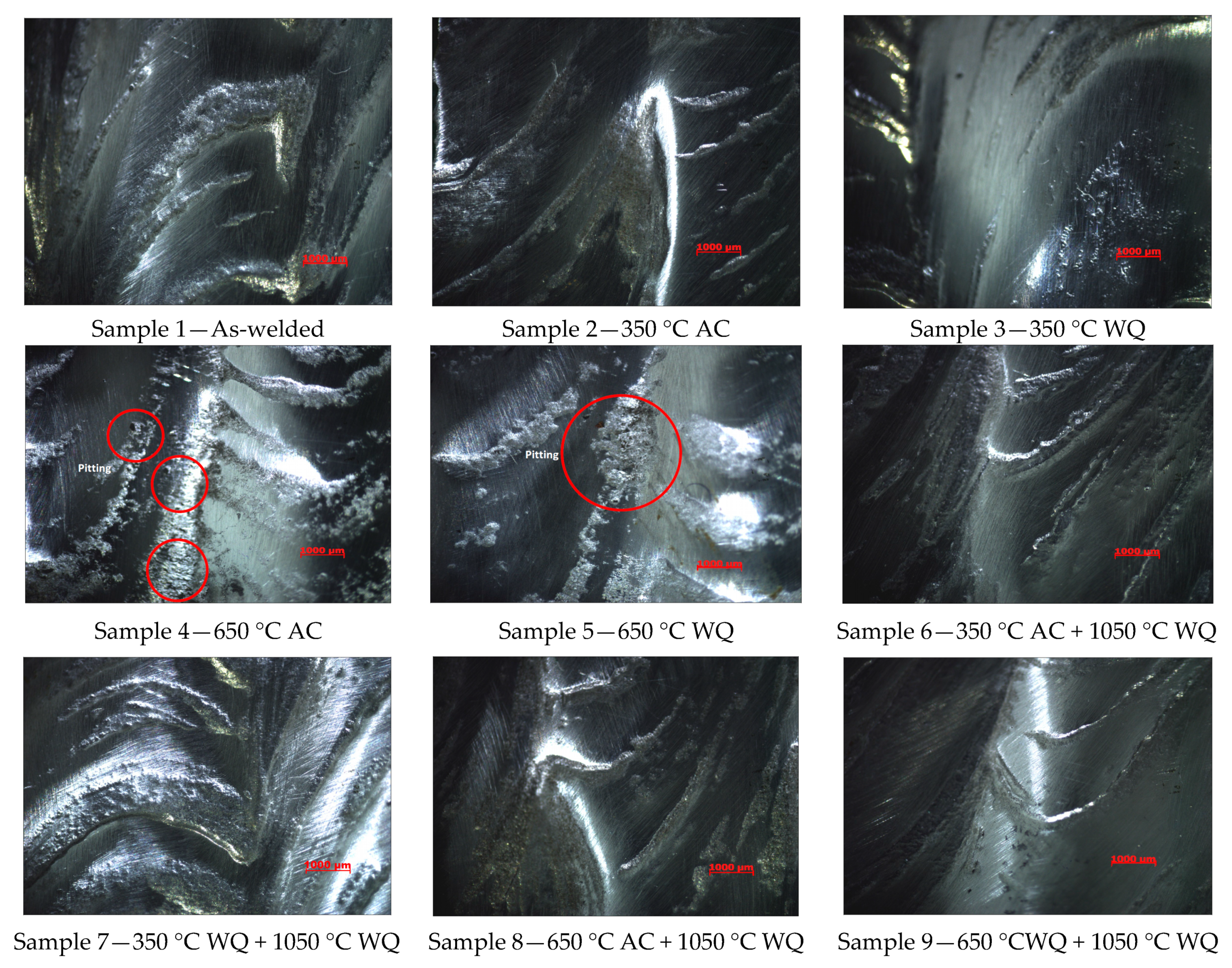
3.1. Pitting Corrosion Properties of Weld Metals
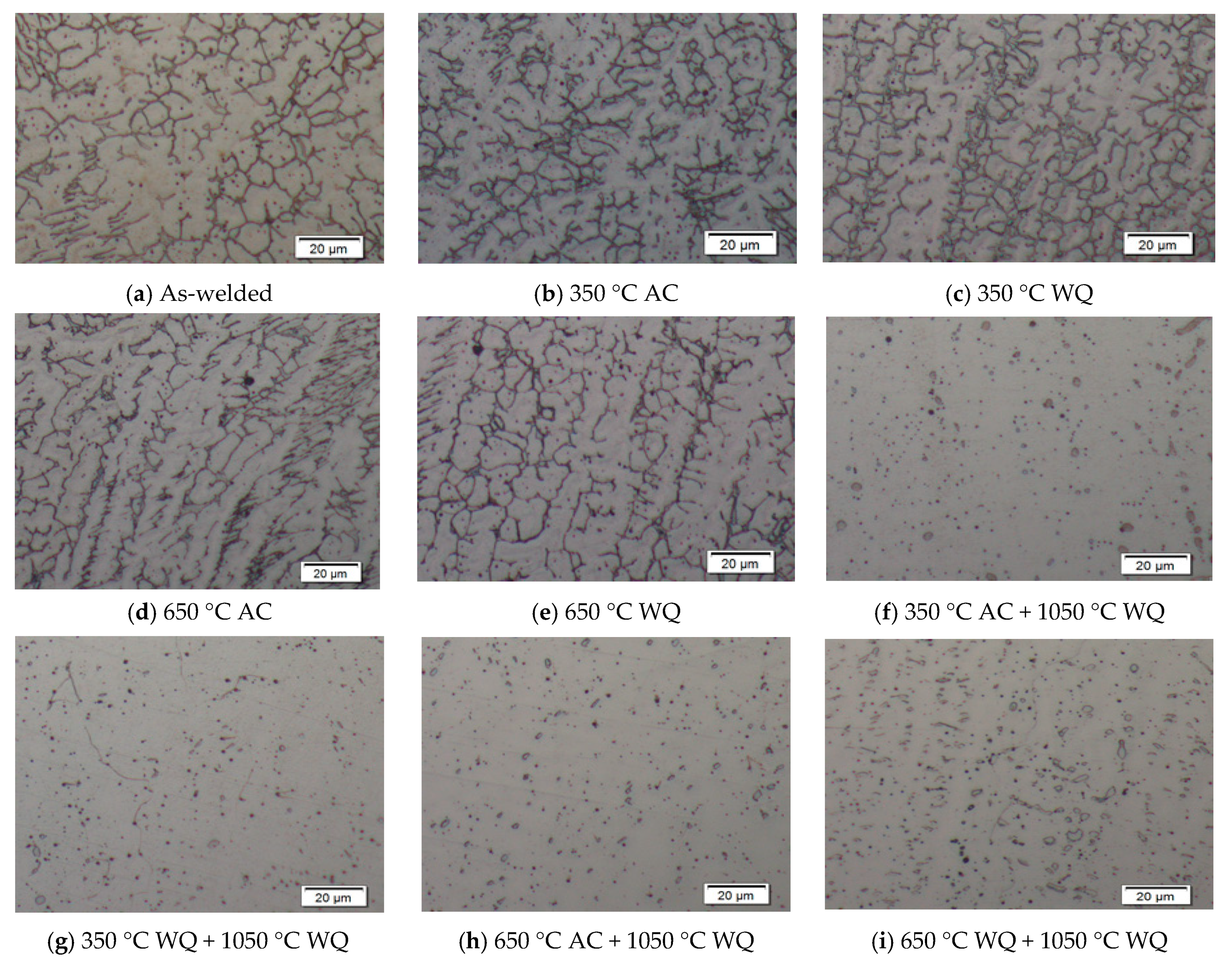
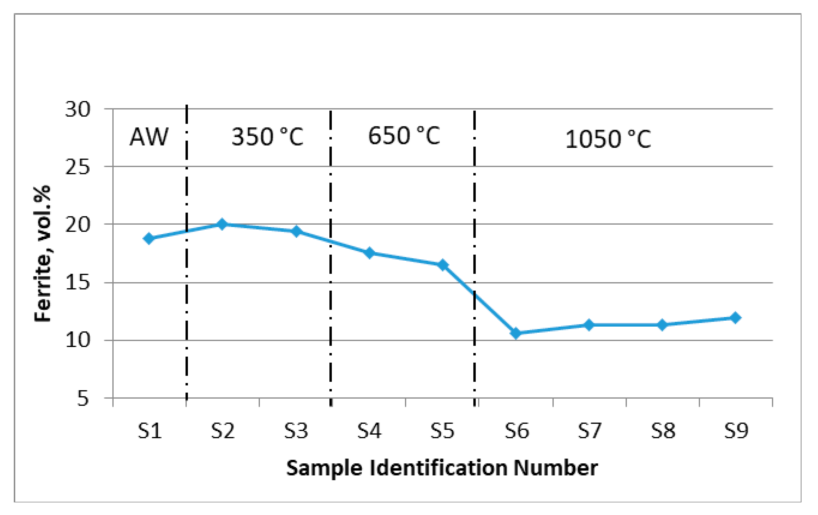
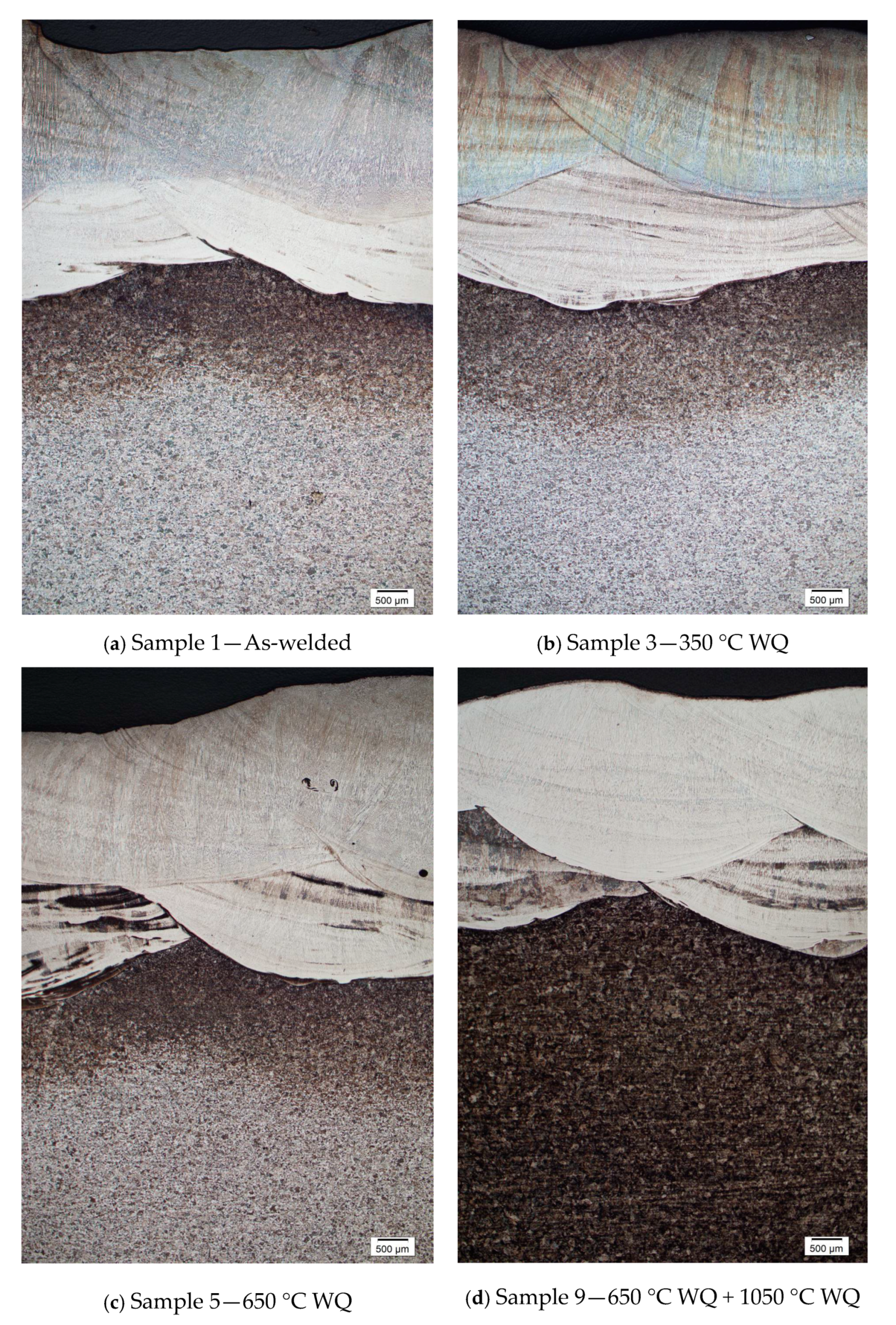
3.2. Volume Fraction of Ferrite
3.3. Dilution of Weld Metal
4. Conclusions
Author Contributions
Funding
Conflicts of Interest
References
- Gholami, M.; Hoseinpoor, M.; Moayed, M.H. A Statistical Study on the Effect of Annealing Temperature on Pitting Corrosion Resistance of 2205 Duplex Stainless Steel. Corros. Sci. 2015, 94, 156–164. [Google Scholar] [CrossRef]
- Shaoning, G.; Junsheng, S.; Lingyu, G.; Wang, H. Evolution of Microstructure and Corrosion Behavior in 2205 Duplex Stainless Steel GTA-Welding Joint. J. Manuf. Process. 2015, 19, 32–37. [Google Scholar]
- Abbas, E.; Keyvan, R.; Morteza, S. Tribocorrosion Behavior of Overlay Welded Super Duplex Stainless Steel Ii Chloride Medium. J. Bio Tribo-Corros. 2015, 1, 18. [Google Scholar]
- Chung, M.L.; Te, L.S.; Keo, Y.W. Effects of Parameter Optimization on Microstructure and Properties of GTAW Clad Welding on AISI 304L Stainless Steel Using Inconel 52M. Int. J. Adv. Manuf. Technol. 2015, 79, 2057–2066. [Google Scholar]
- Marques, M.J.; Ramasamy, A.; Batista, A.C.; Nobre, J.P.; Loureiro, A. Effect of heat treatment on microstructure and residual stress fields of a weld multilayer austenitic steel clad. J. Mater. Process. Technol. 2015, 222, 52–60. [Google Scholar] [CrossRef]
- PTS 31.40.20.32. CRA Clad or Lined Steel Pipe (Amendment/Supplements to API Spec 5LD); Petronas Technical Standard: Kuala Lumpur, Malaysia, 2012. [Google Scholar]
- Balakrishnan, M.; Anburaj, J.; Mohamed, N.S.S.; Neelakantan, L.; Narayanan, R. Influence of Intermetallic Precipitates on Pitting Corrosion of High Mo Superaustenitic Stainless Steel. Trans. Indian Inst. Met. 2015, 68 (Suppl. S2), 267–279. [Google Scholar] [CrossRef]
- Sheng, M.Y.; Yi, C.C.; Chun, H.C.; Wei, P.H.; Dong, Y.L. Microstructural Characterization of δ/γ/σ/γ2/χ Phases in Silver doped 2205 Duplex Stainless Steel Under 800 °C aging. J. Alloys Compd. 2015, 633, 48–53. [Google Scholar]
- Prabhu, P.; Rajnish, G. Effect of Welding Parameters on Pitting Behavior of GTAW of DS and Super DSS Weldments. Eng. Sci. Technol. Int. J. 2016, 19, 1076–1083. [Google Scholar]
- Zanotto, F.; Grassi, V.; Merlin, M.; Balbo, A.; Zucchi, F. Effect of Brief Heat Treatments Performed Between 650 °C and 850 °C on Corrosion Behavior of Lean Duplex Stainless Steel. Corros. Sci. 2015, 94, 38–47. [Google Scholar] [CrossRef]
- ASTM G48. Standard Test Methods for Pitting and Crevice Corrosion Resistance of Stainless Steels and Related Alloys by Use of Ferric Chloride Solution; ASTM International: West Conshohocken, PA, USA, 2015. [Google Scholar]
- PTS 61.40.20.31. Field Welding of Duplex and Super Duplex Stainless Steel Pipelines (Amendments/Suppliments To API 1104); Petronas Technical Standard: Kuala Lumpur, Malaysia, 2011. [Google Scholar]
- DEP 61.40.20.31. Duplex and Super Duplex Stainless Steel Pipelines; Shell Design Engineering Practice Specification: The Hague, The Netherlands, 2011. [Google Scholar]
- ASTM E562. Standard Test Method for Determining Volume Fraction by Systematic Manual Point Count; ASTM International: West Conshohocken, PA, USA, 2011. [Google Scholar]
- Outokumpu Stainless Steel and High Performance Alloys. Duplex Stainless Steel Manual. Citing Internet Source. Available online: https://www.outokumpu.com/ Site Collection Documents/Duplex_Stainless_Brochure.pdf (accessed on 20 December 2016).
- Xinjie, D.; Zhentang, Z.; Caiyan, D.; Dongpo, W.; Guo, X. Microstructural Evolution of Transition Zone of Clad X70 with Duplex Stainless Steel. Mater. Des. 2016, 95, 231–236. [Google Scholar]
- Kchaou, Y.; Haddar, N.; Hénaff, G.; Pelosin, V.; Elleuch, K. Microstructural, Compositional And Mechanical Investigation Of Shielded Metal Arc Welding (SMAW) Welded Superaustenitic UNS N08028 (Alloy 28) Stainless Steel. Mater. Des. 2014, 63, 278–285. [Google Scholar] [CrossRef]
- Metrode Welding Consumables. 22%Cr Duplex Stainless Steels (A126). Citing Internet Source. Available online: www.netlite.com.my/home/wp-content/uploads/2011/11/A126_A132.pdf (accessed on 25 February 2017).
- Jian, L.; Yaling, D.; Longfei, L.; Xiaoming, W. Microstructure of 2205 duplex stainless steel joint in submerged arc welding by post weld heat treatment. J. Manuf. Process. 2014, 16, 144–148. [Google Scholar]
- Zhiqiang, Z.; Honyang, J.; Lianyong, X.; Yongdian, H.; Lei, Z.; Jianli, Z. Influence of microstructure and elemental partioning on pitting corrosion resistance of duplex stainless steel welding joints. Appl. Surf. Sci. 2017, 394, 297–314. [Google Scholar]
- Troels, M.; Asbjørn, A. Challenges in Pre-Qualification Corrosion Testing of CRAs based on ASTM G48. In Proceedings of the NACE Corrosion 2014, San Antonio, TX, USA, 9–13 March 2014. [Google Scholar]
- Naghizadeh, M.; Moayed, M.H. Investigation Of The Effect Of Solution Annealing Temperature On Critical Pitting Temperature of 2205 Duplex Stainless Steel By Measuring Pit Solution Chemistry. Corros. Sci. 2015, 94, 179–189. [Google Scholar] [CrossRef]
- PTS 15.12.01. Welding for Chemical, Oil, and Gas Industries (Amendments/Supplements to API RP 582); Petronas Technical Standard: Kuala Lumpur, Malaysia, 2016. [Google Scholar]
- Offshore standard. Submarine Pipeline Systems; DNV-OS-F101; Det Norske Veritas: Høvik, Norway, October 2010. [Google Scholar]
- ASTM D1193. Standard Specification for Reagent Water; ASTM International: West Conshohocken, PA, USA, 2011. [Google Scholar]
- ASTM A923. Standard Test Methods for Detecting Detrimental Intermetallic Phase in Duplex Austenitic/Ferritic Stainless Steels; ASTM International: West Conshohocken, PA, USA, 2014. [Google Scholar]
- PTS 15.12.04. Welding of Pipelines and Related Facilities (Amendments/Supplements to API Standard 1104); Petronas Technical Standard: Kuala Lumpur, Malaysia, 2015. [Google Scholar]


| Test Materials | Chemical Composition, wt% | |||||||||
|---|---|---|---|---|---|---|---|---|---|---|
| C | Cr | Ni | Mo | Mn | Si | Nb | Ti | Cu | N | |
| Electrode (E2209-16) | 0.014 | 23.49 | 10.45 | 3.55 | 1.32 | 0.53 | 0.012 | 0.028 | 0.051 | 0.16 |
| Base Metal (DMR 249A) | 0.110 | 0.30 | 1.05 | 0.05 | 1.65 | 0.40 | 0.05 | 0.06 | 0.30 | - |
| Electrode | Current Polarity | Ampere (A) | Voltage (V) | Travel Speed (mm/min) | Heat Input (kJ/mm) |
|---|---|---|---|---|---|
| E2209-16, Ø4.0 mm | DCEP | 120–125 | 22–25 | 130–145 | 1.22–1.29 |
| Heat Treatment | Sample No. | Holding | Cooling Method (s) | |
|---|---|---|---|---|
| Temperature | Time | |||
| PWHT | S1 | Without heat treatment (As welded condition) | ||
| S2 & S6 | 350 °C | 25 mm/h | Air Cool | |
| S3 & S7 | Water Quench | |||
| S4 & S8 | 650 °C | 25 mm/h | Air Cool | |
| S5 & S9 | Water Quench | |||
| Solution Annealing | S6 | 1050 °C | 2 h | Water Quench |
| S7 | Water Quench | |||
| S8 | 1050 °C | 2 h | Water Quench | |
| S9 | Water Quench | |||
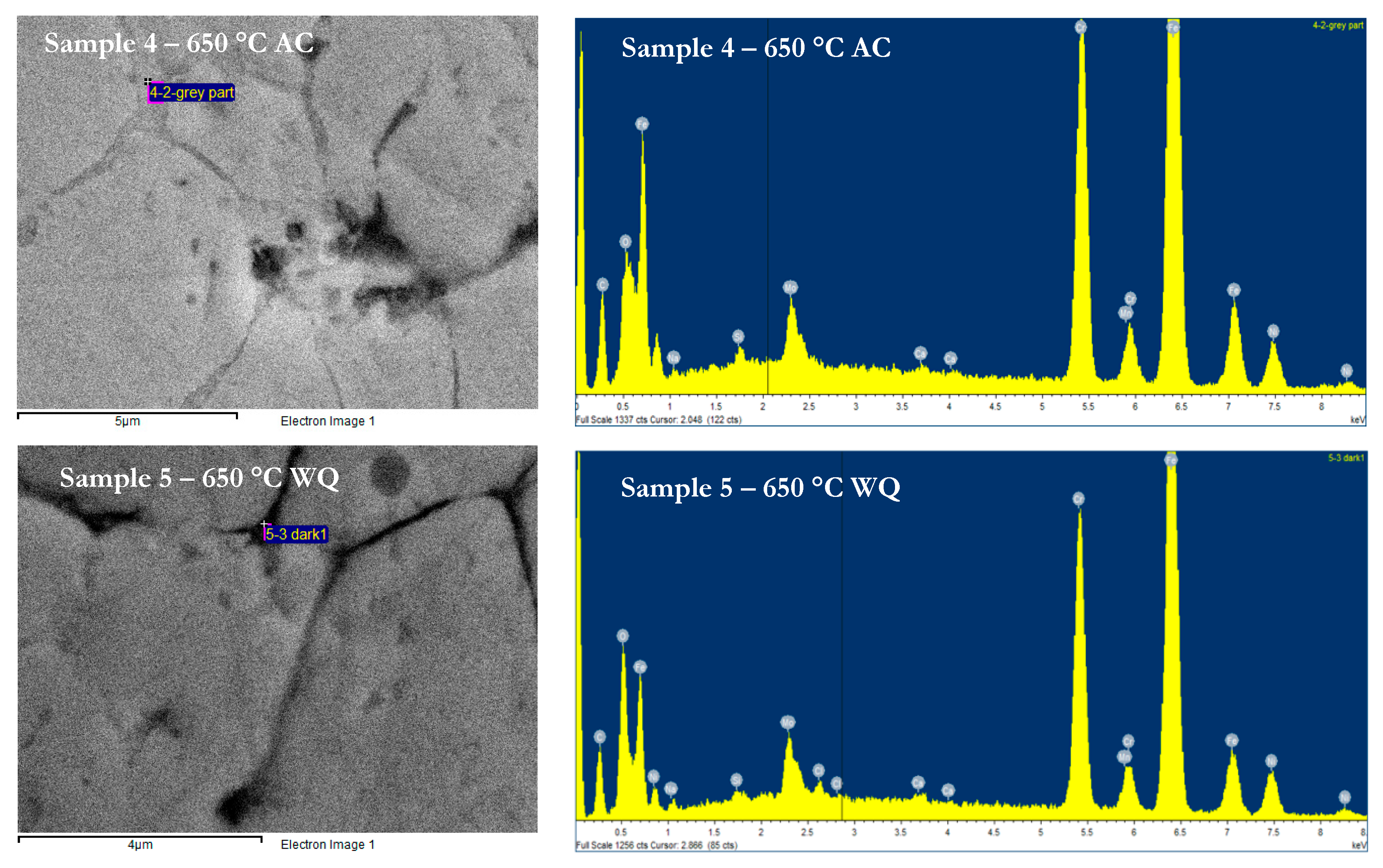
| Sample ID | PWHT | Mass Loss | Cr | Mo | Mn | Fe | Ni | Si | Type of Intermetallic Phase |
|---|---|---|---|---|---|---|---|---|---|
| °C | g/m2 | wt% | |||||||
| 4 | 650 AC | 3.30 | 22.58 | 4.50 | 0.93 | 59.82 | 6.60 | 0.53 | Sigma |
| 5 | 650 WQ | 3.13 | 21.75 | 5.03 | 0.73 | 53.45 | 7.42 | 0.26 | Sigma |
© 2019 by the authors. Licensee MDPI, Basel, Switzerland. This article is an open access article distributed under the terms and conditions of the Creative Commons Attribution (CC BY) license (http://creativecommons.org/licenses/by/4.0/).
Share and Cite
Sim, B.-M.; Hong, T.-S.; Hanim, M.A.-A.; Tchan, E.-J.N.; Talari, M.-K. The Influence of Post Weld Heat Treatment Precipitation on Duplex Stainless Steels Weld Overlay towards Pitting Corrosion. Materials 2019, 12, 3285. https://doi.org/10.3390/ma12203285
Sim B-M, Hong T-S, Hanim MA-A, Tchan E-JN, Talari M-K. The Influence of Post Weld Heat Treatment Precipitation on Duplex Stainless Steels Weld Overlay towards Pitting Corrosion. Materials. 2019; 12(20):3285. https://doi.org/10.3390/ma12203285
Chicago/Turabian StyleSim, Bernard-Maxmillan, Tang-Sai Hong, Mohamed Arif-Azmah Hanim, Edwin-Jong Nyon Tchan, and Mahesh-Kumar Talari. 2019. "The Influence of Post Weld Heat Treatment Precipitation on Duplex Stainless Steels Weld Overlay towards Pitting Corrosion" Materials 12, no. 20: 3285. https://doi.org/10.3390/ma12203285
APA StyleSim, B.-M., Hong, T.-S., Hanim, M. A.-A., Tchan, E.-J. N., & Talari, M.-K. (2019). The Influence of Post Weld Heat Treatment Precipitation on Duplex Stainless Steels Weld Overlay towards Pitting Corrosion. Materials, 12(20), 3285. https://doi.org/10.3390/ma12203285