Effect of Ti Addition on the Microstructure and Mechanical Properties of SiC Matrix Composites Infiltrated by Al–Si (10 wt.%)–xTi Alloy

Abstract
1. Introduction
2. Materials and Methods
2.1. Material Preparation
2.2. Microstructure and Phase Composition
2.3. Mechanical Properties
3. Results and Discussion
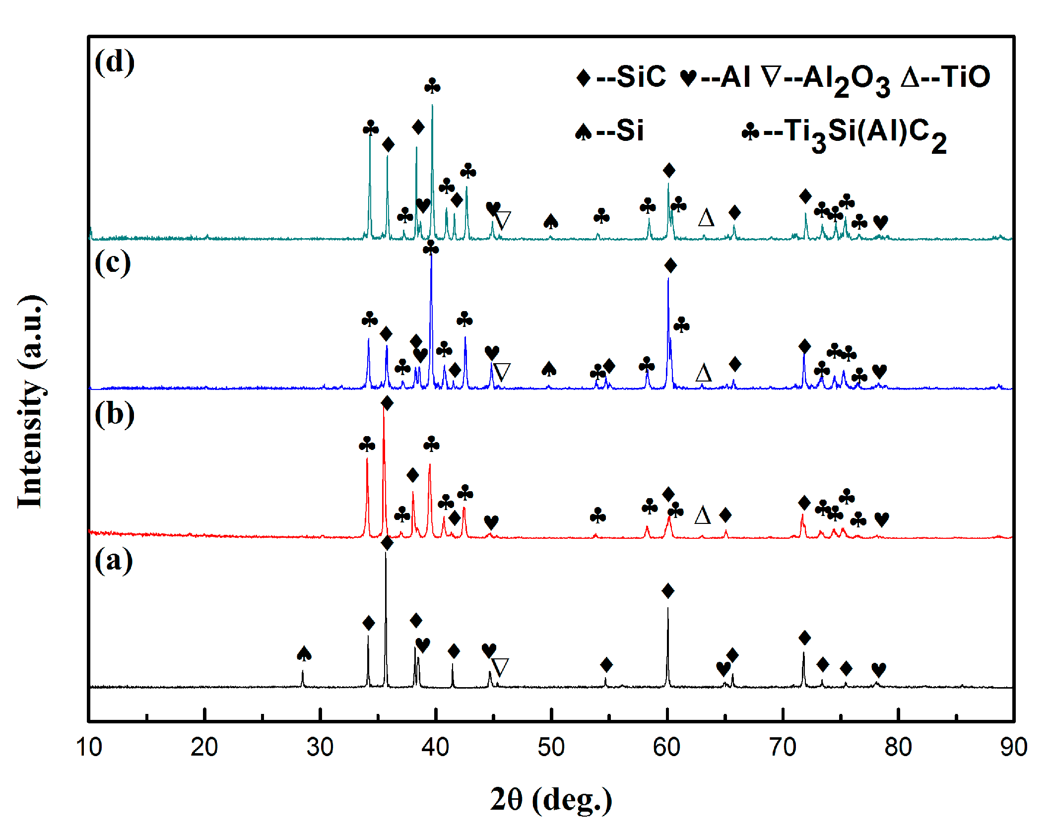
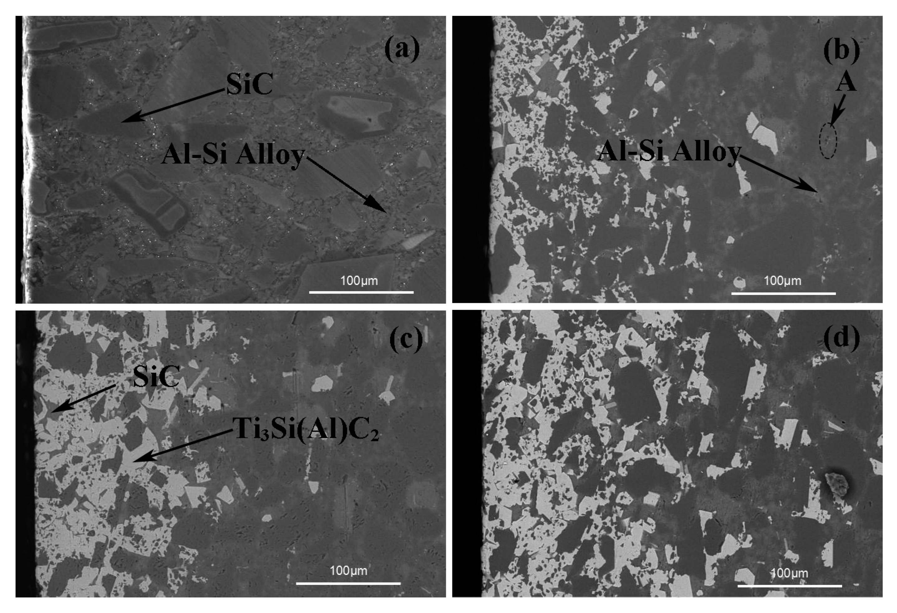
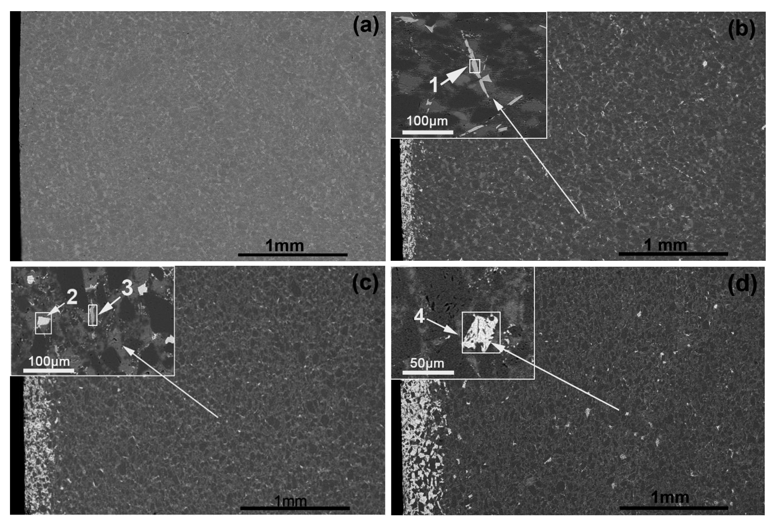
3.1. Phase Composition, Microstructure, and Infiltration Process
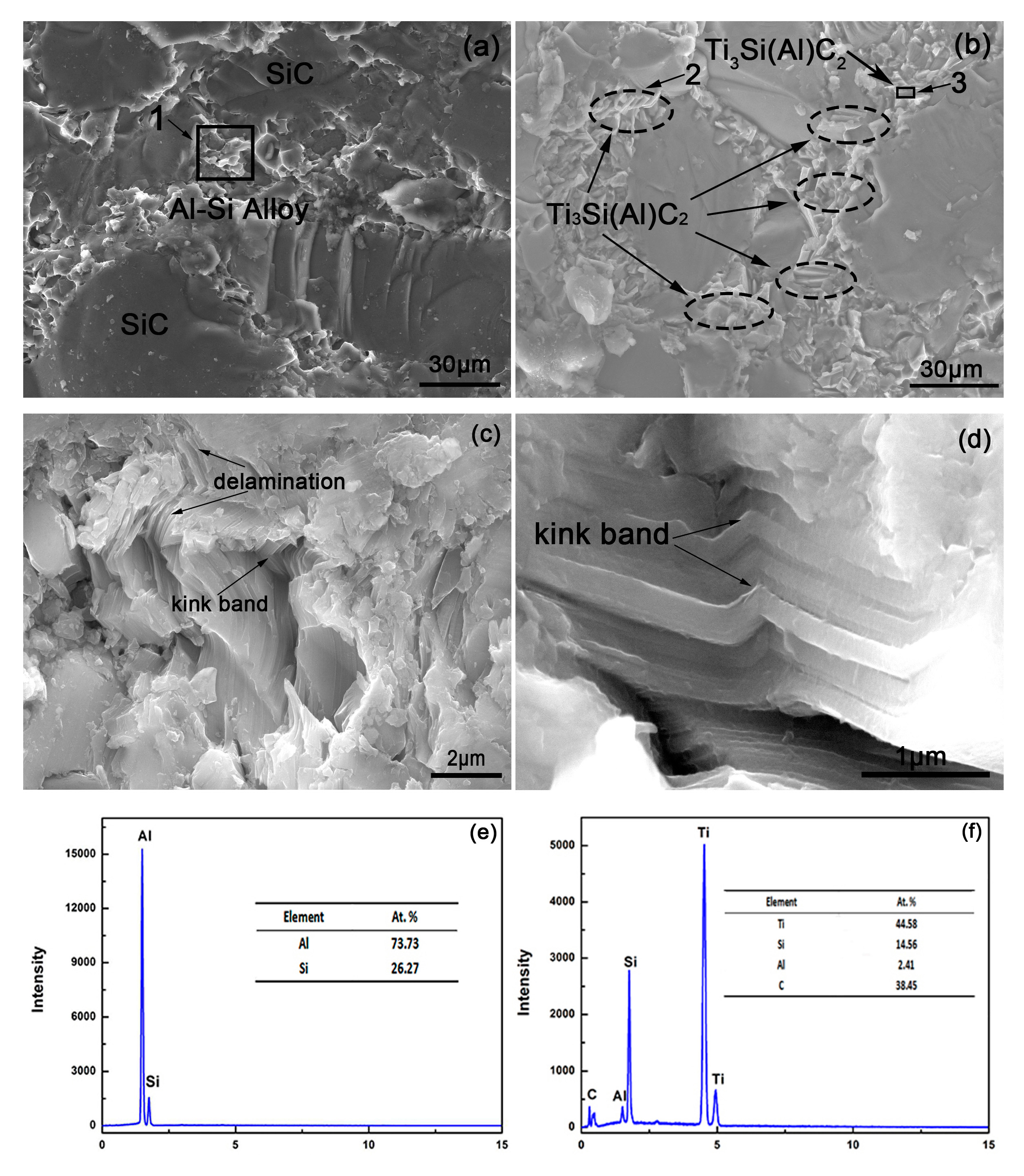
3.2. Mechanical Properties
4. Conclusions
Author Contributions
Funding
Acknowledgments
Conflicts of Interest
References
- Cao, X.Y.; Yin, X.W.; Ma, X.K. The microstructure and properties of SiC/SiC-based composites fabricated by low-temperature melt infiltration of Al–Si alloy. Ceram. Int. 2016, 42, 10144–10150. [Google Scholar] [CrossRef]
- Zhang, L.; Xu, H.; Wang, Z.; Li, Q.; Wu, J. Mechanical properties and corrosion behavior of Al/SiC composites. J. Alloy Compd. 2016, 678, 23–30. [Google Scholar] [CrossRef]
- Sha, J.J.; Zhang, Z.F.; Di, S.X. Microstructure and mechanical properties of ZrB2-based ceramic composites with nano-sized SiC particles synthesized by in-situ reaction. Mater. Sci. Eng. A 2017, 693, 145–150. [Google Scholar] [CrossRef]
- Araki, H.; Noda, T.; Yang, W. Homogeneity and flexural properties of SiC/SiC composites prepared by CVI method. J. Nucl. Mater. 2002, 307–311, 1210–1214. [Google Scholar] [CrossRef]
- Dong, Z.J.; Liu, S.X.; Li, X.K. Influence of infiltration temperature on the microstructure and oxidation behavior of SiC–ZrC ceramic coating on C/C composites prepared by reactive melt infiltration. Ceram. Int. 2015, 41, 797–811. [Google Scholar] [CrossRef]
- Turki, F.; Abderrazak, H.; Schoenstein, F. SPS parameters influence on Ti3SiC2 formation from Si/TiC: Mechanical properties of the bulk materials. J. Alloys Compd. 2017, 708, 123–133. [Google Scholar] [CrossRef]
- Abdollahi, A.; Ehsani, N.; Valefi, Z. Thermal shock resistance and isothermal oxidation behavior of C/SiC-SiCnano functionally gradient coating on graphite produced via reactive melt infiltration (RMI). Mater. Chem. Phys. 2016, 182, 49–61. [Google Scholar] [CrossRef]
- Fan, X.M.; Yin, X.W.; Wang, L. Synthesis of Ti3SiC2-based materials by reactive melt infiltration. J. Refract. Met. Hard Mater. 2014, 45, 1–7. [Google Scholar] [CrossRef]
- Hashim, J. The wettability of SiC particles by molten aluminum alloy. J. Mat. Proc. Technol. 2001, 119, 324–328. [Google Scholar] [CrossRef]
- Che, Z.F.; Zhang, Y.; Li, J.W. Nucleation and growth mechanisms of interfacial Al4C3 in Al/diamond composites. J. Alloys Compd. 2016, 657, 81–89. [Google Scholar] [CrossRef]
- Selvam, D.R.; Dinaharan, R.S.D.S. Synthesis and characterization of Al6061-Fly Ashp-SiCp composites by stir casting and compocasting methods. Energy Procedia 2013, 34, 637–646. [Google Scholar] [CrossRef]
- Rodriguez-Reyes, M.; Pech-Canul, M.I.; Parga-Torres, J.R. Development of aluminum hydroxides in Al–Mg–Si/SiCp in infiltrated composites exposed to moist air. Ceram. Int. 2011, 37, 2719–2722. [Google Scholar] [CrossRef]
- Cong, X.S.; Shen, P.; Wang, Y.; Jiang, Q. Wetting of polycrystalline SiC by molten Al and Al−Si alloys. Appl. Surf. Sci. 2014, 317, 140–146. [Google Scholar] [CrossRef]
- Alfonso, I.; Navarro, O.; Vargas, J. FEA evaluation of the Al4C3 formation effect on the Young’s modulus of carbon nanotube reinforced aluminum matrix composites. Compos. Struct. 2015, 127, 420–425. [Google Scholar] [CrossRef]
- Xie, B.; Wang, X.G. Thermo-physical Properties and Reaction Process of SiCp/Al-7Si-5Mg Aluminum Matrix Composites Fabricated by Pressureless Infiltration. Rare Met. Mater. Eng. 2015, 44, 1057–1061. [Google Scholar] [CrossRef]
- Ni, Z.L.; Zhao, H.J.; Mi, P.B. Effect of sintering time on the bending strength and CTE of SiC/Al-35Si composite. Vacuum 2016, 124, 28–31. [Google Scholar] [CrossRef]
- Wang, W.; Li, Q.; Ma, R.N. Superior bending and impact properties of SiC matrix composites infiltrated with an aluminium alloy. Ceram. Int. 2017, 43, 4551–4556. [Google Scholar] [CrossRef]
- Foratirad, H.; Baharvandi, H.; Maraghe, M.G. Effect of excess silicon content on the formation of nano-layered Ti3SiC2 ceramic via infiltration of TiC preforms. J. Eur. Ceram. Soc. 2017, 37, 451–457. [Google Scholar] [CrossRef]
- Zou, Y.; Sun, Z.; Tada, S.; Hashimoto, H. Effect of Al addition on low-temperature synthesis of Ti3SiC2 powder. J. Alloy Compd. 2008, 461, 579–584. [Google Scholar] [CrossRef]
- Fan, X.M.; Yin, X.W.; Wang, L. Processing, microstructure and ablation behavior of C/SiC–Ti3SiC2 composites fabricated by liquid silicon infiltration. Corros. Sci. 2013, 74, 98–105. [Google Scholar] [CrossRef]
- ASTM C1421-18. Standard Test Methods for Determination of Fracture Toughness of Advanced Ceramics at Ambient Temperature; ASTM International: West Conshohocken, PA, USA, 2018; Available online: www.astm.org (accessed on 1 January 2018).
- Anstis, G.R.; Chantikul, P.; Lawn, B.R.; Marshall, D.B. A critical evaluation of indentation techniques for measuring fracture toughness: I direct crack measurements. J. Am. Ceram. Soc. 1981, 64, 533–538. [Google Scholar] [CrossRef]
- Lin, Q. Wettability and Spreading Dynamics of Carbide Ceramics by Molten Metals; Jilin University: Jilin, China, 2011. [Google Scholar]
- Narciso, J.; Molina, J.M.; Rodríguez, A.; Rodríguez-Reinoso, F.; Louis, E. Effects of infiltration pressure on mechanical properties of Al-12Si/graphite composites for piston engines. Compos. Part B 2016, 91, 441–447. [Google Scholar] [CrossRef]
- Rodríguez-Guerrero, A.; Sánchez, S.A.; Narciso, J.; Louis, E.; Rodrı´guez-Reinoso, F. Pressure infiltration of Al-12 wt.% Si-X (X = Cu, Ti, Mg) alloys into graphite particle preforms. Acta Mater. 2006, 54, 1821–1831. [Google Scholar] [CrossRef]
- Wu, H.; Jin, B.C.; Geng, L.; Fan, G.; Cui, X.; Huang, M.; Hicks, R.M.; Nutt, S. Ductile-Phase Toughening in TiBw/Ti-Ti3Al Metallic-Intermetallic Laminate Composites. Metall. Mat. Trans. A 2015, 46, 3803. [Google Scholar] [CrossRef]


| Alloying Content (wt.%) | ||||
|---|---|---|---|---|
| Al–Si (10 wt.%)–xTi Alloy | x = 0 | x = 5 | x = 10 | x = 15 |
| Ti | 0 | 5 | 10 | 15 |
| Si | 10 | 10 | 10 | 10 |
| Al | 90 | 85 | 80 | 75 |
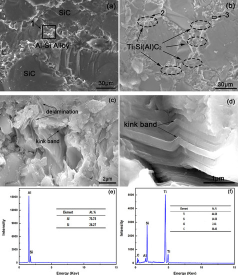
| Region | AlK (at.%) | SiK (at.%) | CK (at.%) | TiK (at.%) |
|---|---|---|---|---|
| SiC | 1.66 | 39.32 | 58.20 | 0.82 |
| Ti3Si(Al)C2 | 6.79 | 16.43 | 30.40 | 46.38 |
| A | 62.82 | 25.75 | 11.43 | - |
| Region | AlK (at.%) | SiK (at.%) | CK (at.%) | TiK (at.%) |
|---|---|---|---|---|
| 1 | 48.07 | 10.91 | 22.79 | 18.23 |
| 2 | 11.22 | 51.26 | 7.54 | 29.98 |
| 3 | 62.77 | 13.60 | 2.17 | 21.46 |
| 4 | 11.94 | 50.88 | 6.68 | 30.50 |
| Composites Infiltrated by Al–Si–xTi Alloy (Si: 10 wt.%) | x = 0 | x = 5 | x = 10 | x = 15 |
|---|---|---|---|---|
| KIC (MPa·m1/2) | 2.87 | 5.78 | 6.16 | 6.56 |
© 2019 by the authors. Licensee MDPI, Basel, Switzerland. This article is an open access article distributed under the terms and conditions of the Creative Commons Attribution (CC BY) license (http://creativecommons.org/licenses/by/4.0/).
Share and Cite
Yu, Y.; Du, A.; Zhao, X.; Fan, Y.; Ma, R.; Li, S.; Wang, W.; Cui, Y.; Cao, X. Effect of Ti Addition on the Microstructure and Mechanical Properties of SiC Matrix Composites Infiltrated by Al–Si (10 wt.%)–xTi Alloy. Materials 2019, 12, 318. https://doi.org/10.3390/ma12020318
Yu Y, Du A, Zhao X, Fan Y, Ma R, Li S, Wang W, Cui Y, Cao X. Effect of Ti Addition on the Microstructure and Mechanical Properties of SiC Matrix Composites Infiltrated by Al–Si (10 wt.%)–xTi Alloy. Materials. 2019; 12(2):318. https://doi.org/10.3390/ma12020318
Chicago/Turabian StyleYu, Yajun, An Du, Xue Zhao, Yongzhe Fan, Ruina Ma, Shijie Li, Wei Wang, Yaqi Cui, and Xiaoming Cao. 2019. "Effect of Ti Addition on the Microstructure and Mechanical Properties of SiC Matrix Composites Infiltrated by Al–Si (10 wt.%)–xTi Alloy" Materials 12, no. 2: 318. https://doi.org/10.3390/ma12020318
APA StyleYu, Y., Du, A., Zhao, X., Fan, Y., Ma, R., Li, S., Wang, W., Cui, Y., & Cao, X. (2019). Effect of Ti Addition on the Microstructure and Mechanical Properties of SiC Matrix Composites Infiltrated by Al–Si (10 wt.%)–xTi Alloy. Materials, 12(2), 318. https://doi.org/10.3390/ma12020318