Effect of Lubricating Phase on Microstructure and Properties of Cu–Fe Friction Materials


Abstract
:1. Introduction
2. Materials and Methods
2.1. Raw Materials
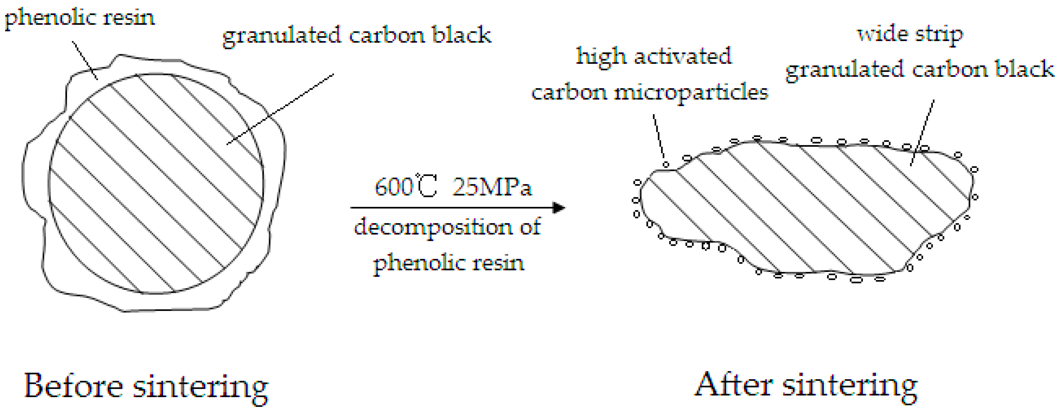
2.2. Lubricating Phase Preparation
2.3. Friction Materials Preparation
2.4. Characterization
3. Results and Discussion
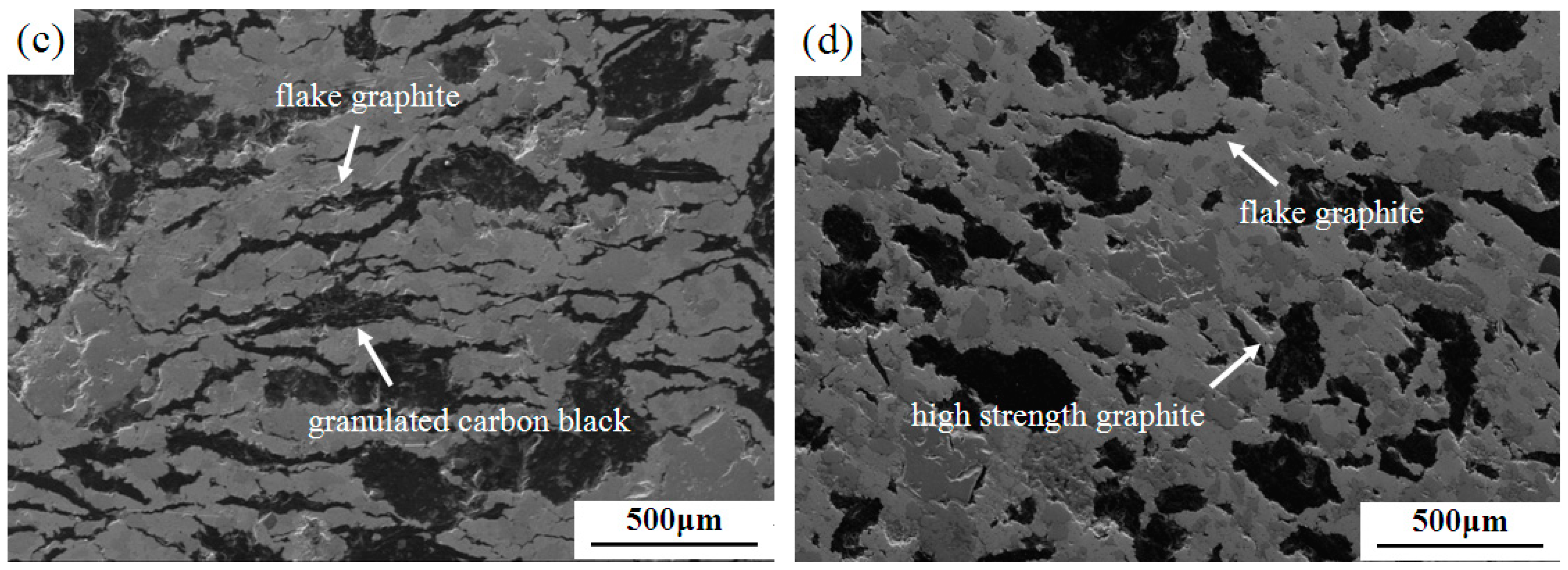
3.1. Microstructures of Materials
3.2. Sintering and Mechanical Properties of Materials
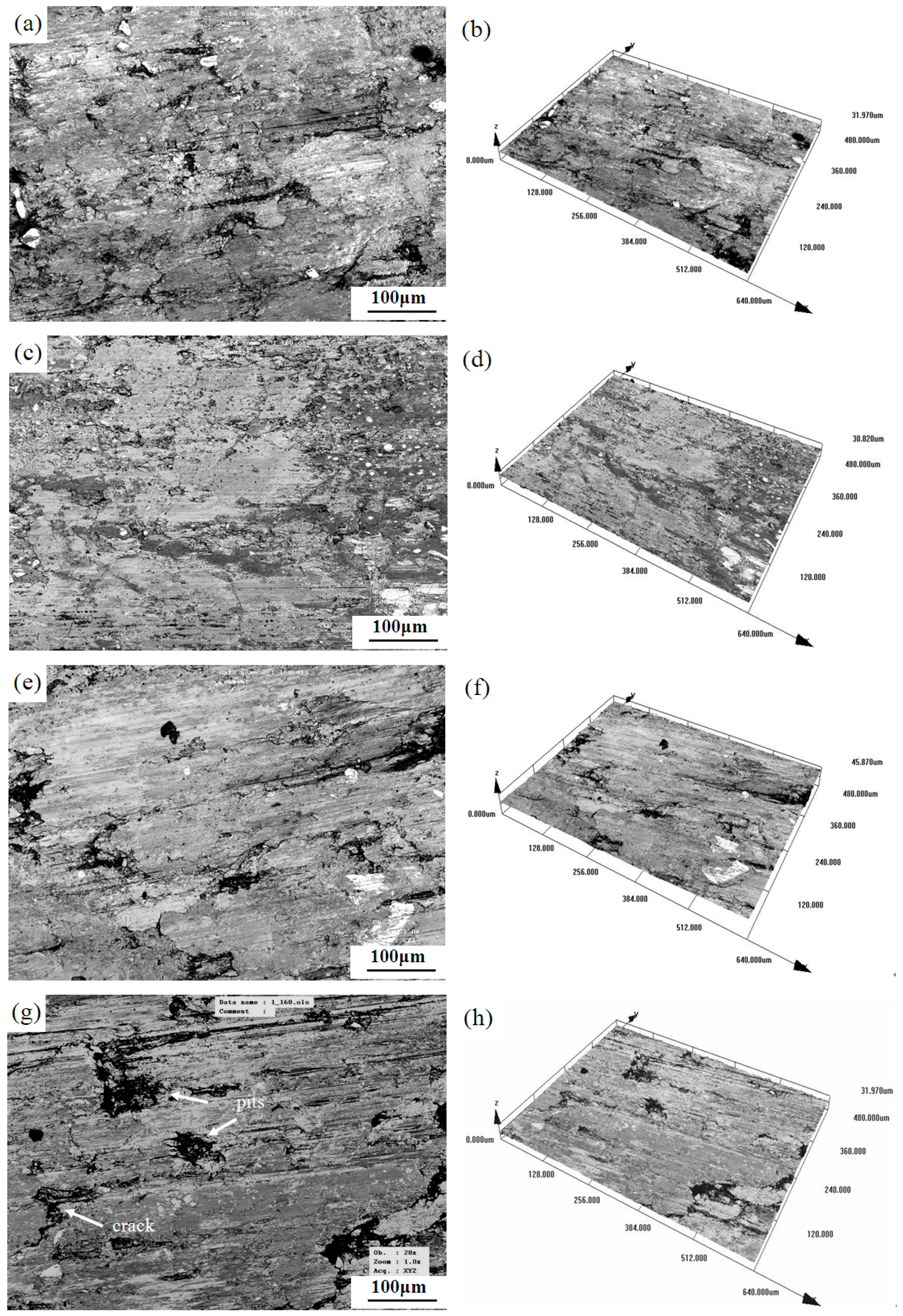
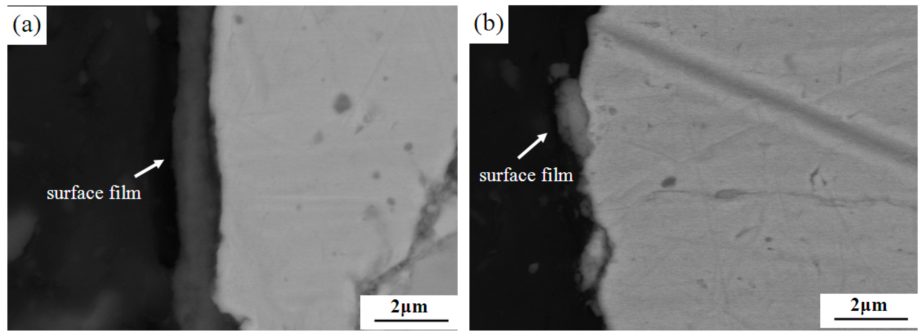
3.3. Worn Surface Analysis
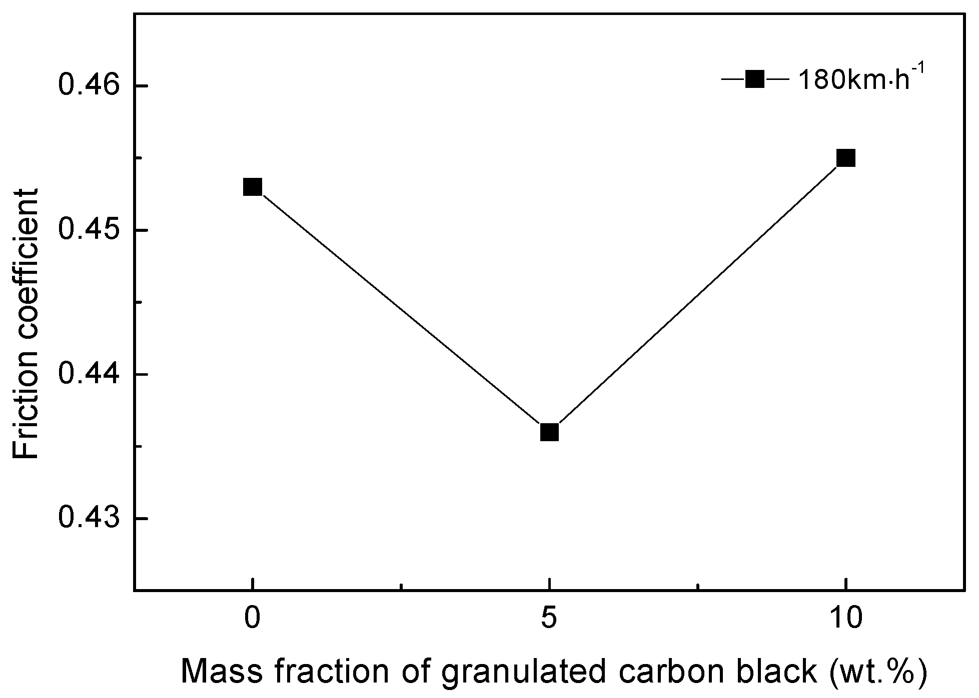
3.4. Effect of Mass Fraction of Granulated Carbon Black on Friction Coefficient of Materials
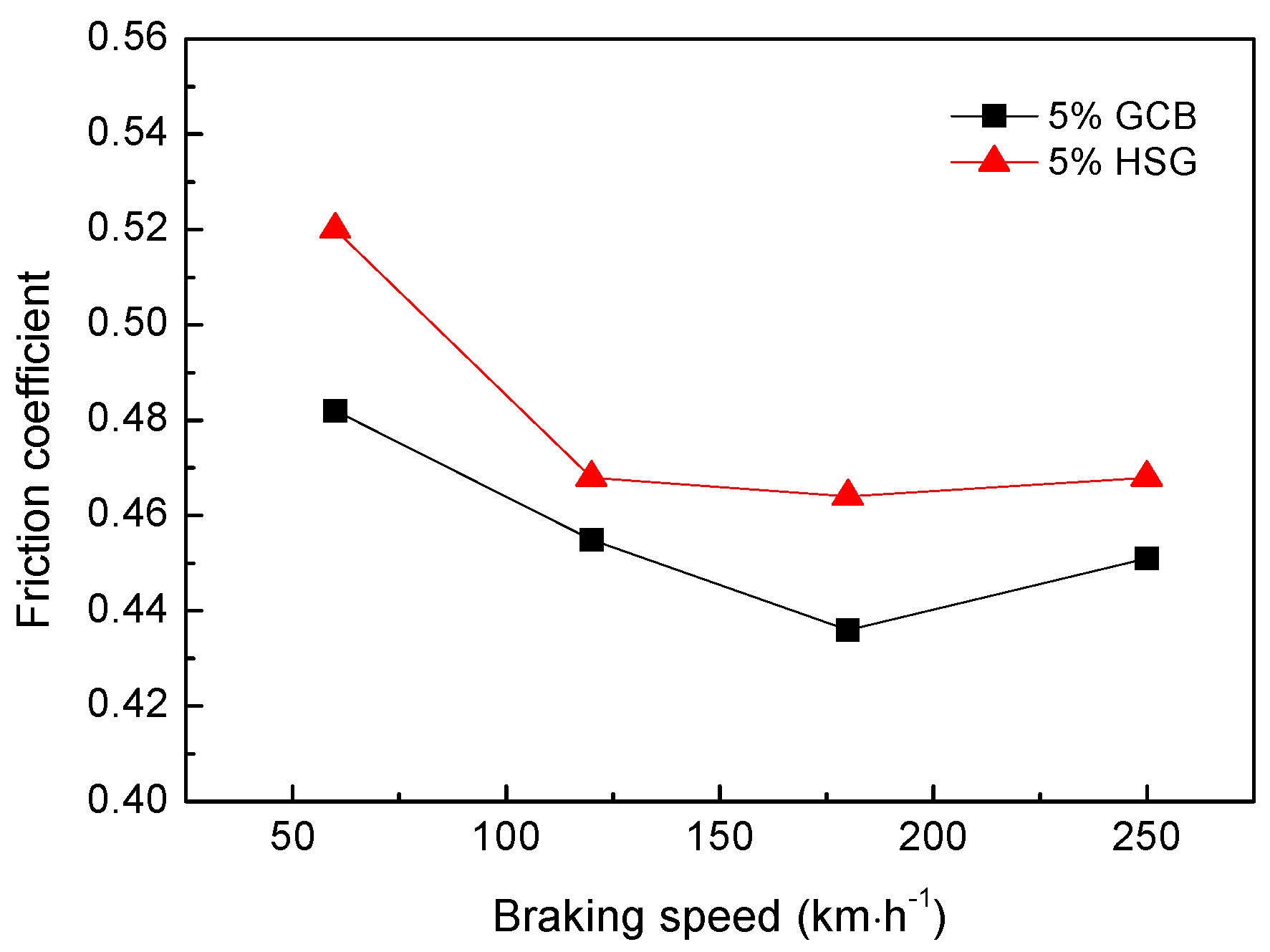
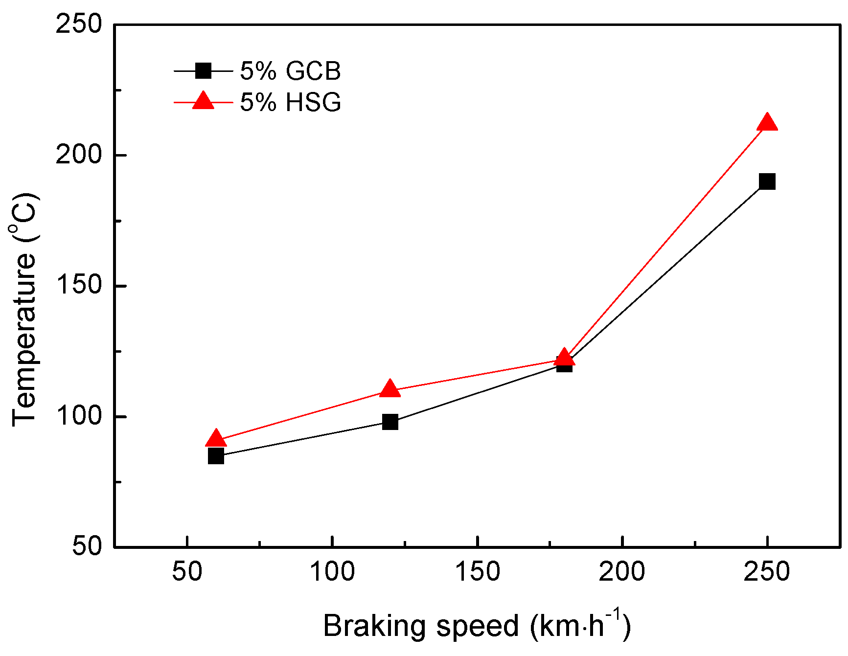
3.5. Effect of Different Lubricating Phase on Friction Coefficient of Materials
3.6. Effect of Mass Fraction of Granulated Carbon Black on Wear Loss of Materials
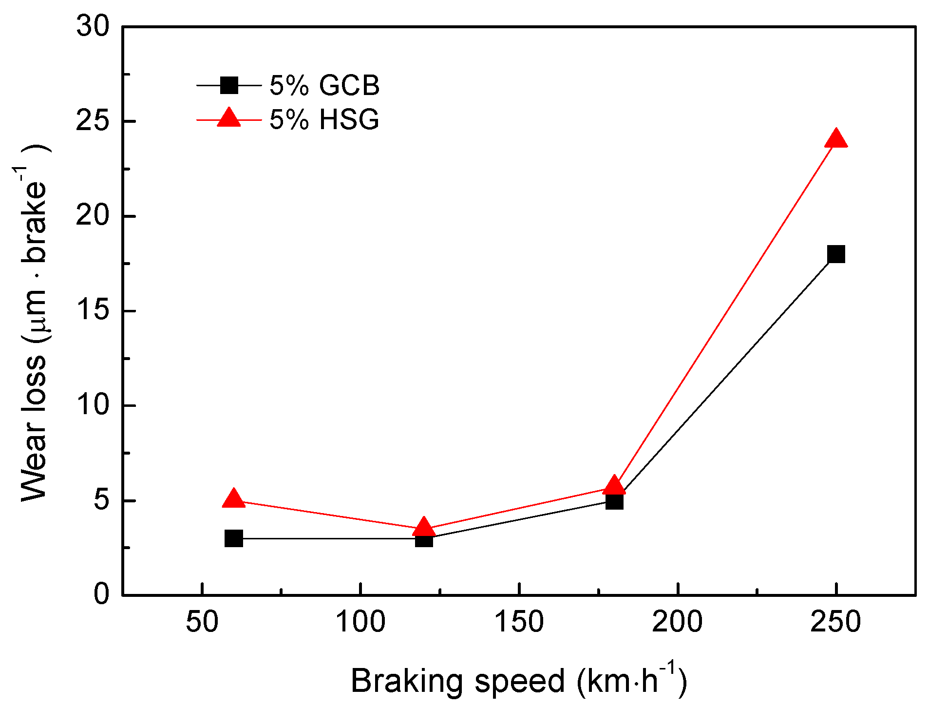
3.7. Effect of Different Lubricating Phase on Wear Loss of Materials
4. Conclusions
- (1)
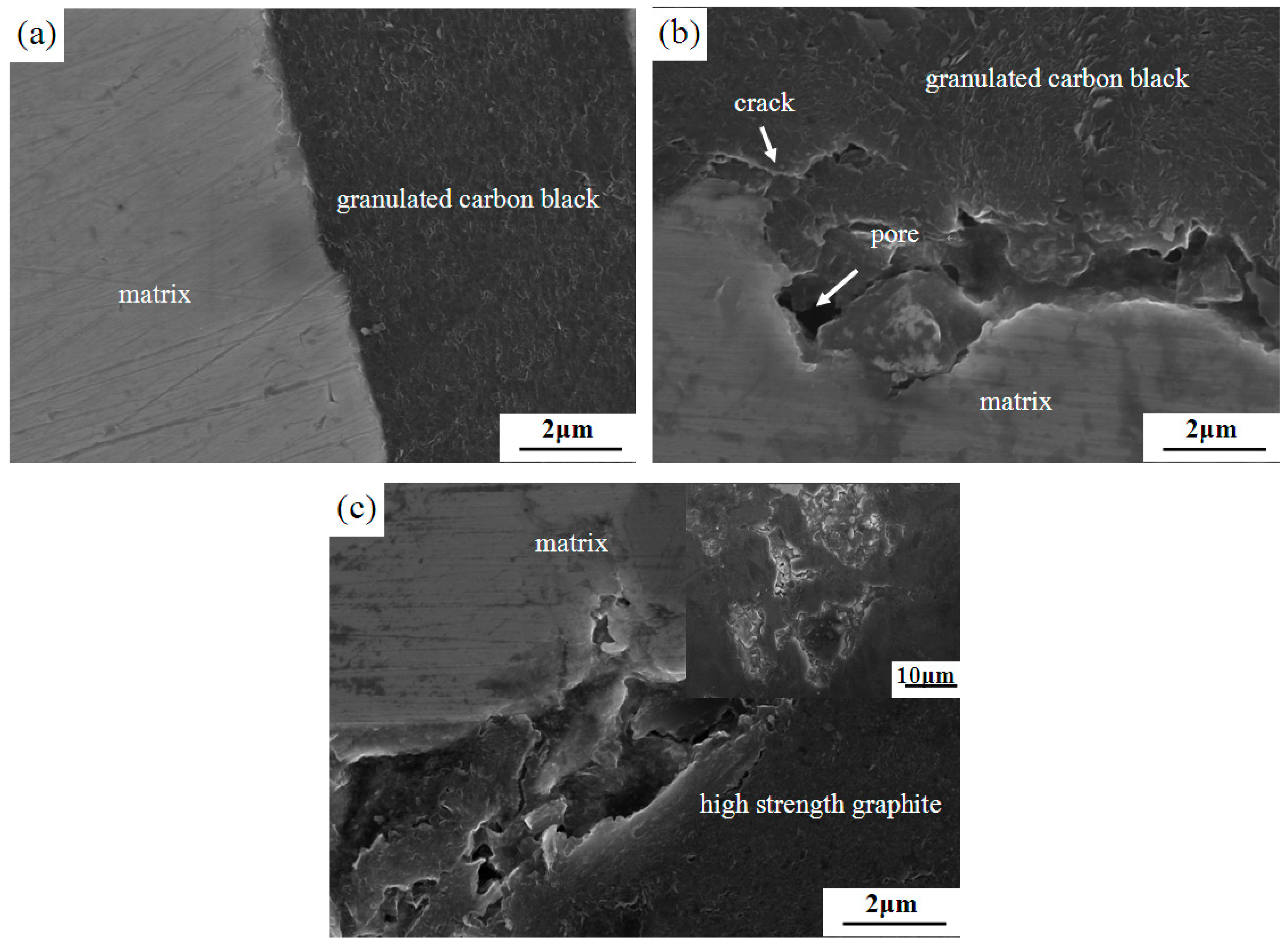
- The mass fraction of granulated carbon black was 5 wt%, and it was easy to form a good interface with the matrix, but the interface was prone to pores and cracks when its mass fraction was 10 wt%. The interface between the high-strength graphite and matrix was also poor.
- (2)
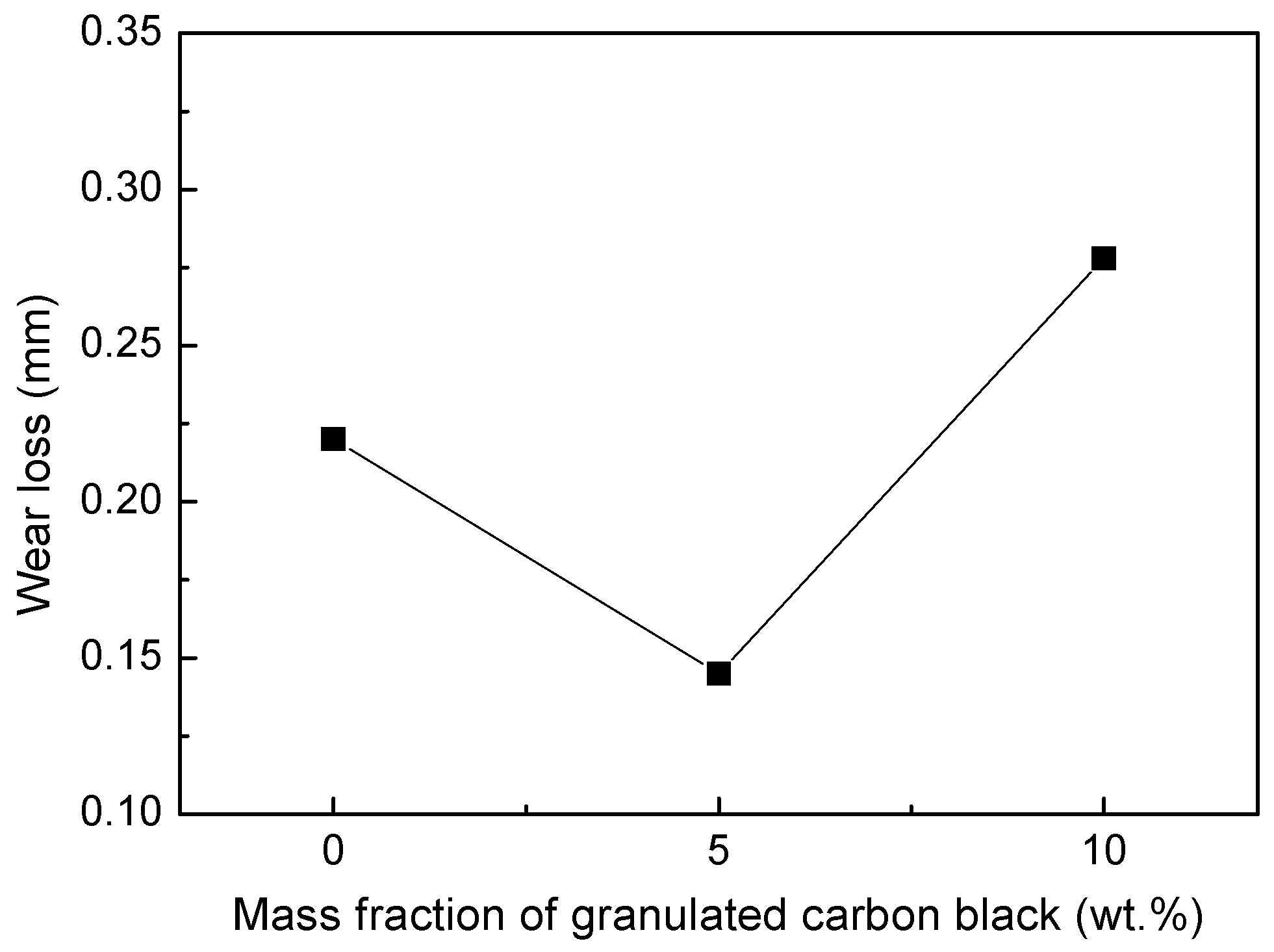
- The bending strength and compressive strength properties of the composites increased with increasing in the mass fraction of granulated carbon black and reached the maximum of 40 MPa and 70 MPa at 5 wt% granulated carbon black, after which bending strength and compressive strength all decreased. The friction coefficient and the wear loss of the materials initially decreased as the mass fraction of granulated carbon black increased and obtained minimum of 0.436 and 0.145 mm when the mass fraction of granulated carbon black was 5 wt%, then ascended.
- (3)
- Compared with the sample with 5 wt% high-strength graphite as lubricating phase, the sample with 5 wt% granulated carbon black as the lubricating phase had better sintering performance and mechanical properties, lower friction coefficient, and wear loss.
Author Contributions
Funding
Acknowledgments
Conflicts of Interest
References
- Gultekin, D.; Uysal, M.; Aslan, S.; Alaf, M.; Guler, M.O.; Akbulut, H. The effect of applied load on the coefficient of friction in Cu-MMC brake pad/Al-SiCp MMC brake disc system. Wear 2010, 270, 73–82. [Google Scholar] [CrossRef]
- Kennedy, F.E.; Balbahadur, A.C.; Lashmore, D.S. The friction and wear of Cu-based silicon carbide particulate metal matrix composites for brake applications. Wear 1997, 203–204, 715–721. [Google Scholar] [CrossRef]
- Uyyuru, R.K.; Surappa, M.K.; Brusethaug, S. Effect of reinforcement volume fraction and size distribution on the tribological behavior of Al-composite/brake pad tribo-couple. Wear 2006, 260, 1248–1255. [Google Scholar] [CrossRef]
- Xiong, X.; Chen, J.; Yao, P.P.; Li, S.P.; Huang, B.Y. Friction and wear behaviors and mechanisms of Fe and SiO2 in Cu-based P/M friction materials. Wear 2007, 262, 1182–1186. [Google Scholar] [CrossRef]
- Hassan, A.M.; Mayyas, A.T.; Alrashdan, A.; Hayajneh, M.T. Wear behavior of Al-Cu and Al-Cu/SiC components produced by powder metallurgy. J. Mater. Sci. 2008, 43, 5368–5375. [Google Scholar] [CrossRef]
- Yang, H.J.; Luo, R.Y.; Han, S.Y.; Li, M.D. Effect of the ratio of graphite/pitch coke on the mechanical and tribological properties of copper-carbon composites. Wear 2010, 268, 1337–1341. [Google Scholar] [CrossRef]
- Zhan, Y.Z.; Zhang, G.D. Graphite and SiC hybrid particles reinforced copper composite and its tribological characteristic. J. Mater. Sci. Lett. 2003, 22, 1087–1089. [Google Scholar] [CrossRef]
- Nakamura, R.; Iwabuchi, A. Role of graphite in cast iron on tribological behavior in nano-scratch test. J. Adv. Mech. Des. Syst. 2012, 6, 1046–1056. [Google Scholar] [CrossRef]
- Méndez, A.; Santamaría, R.; Granda, M.; Menéndez, R. The effect of graphite addition on the mechanical and tribological properties of pitch-based granular carbon composites. J. Mater. Sci. 2008, 43, 4541–4549. [Google Scholar] [CrossRef]
- Cho, M.H.; Ju, J.; Kim, S.J.; Jang, H. Tribological properties of solid lubricants (graphite, Sb2S3, MoS2) for automotive brake friction materials. Wear 2006, 260, 855–860. [Google Scholar] [CrossRef]
- Ghaderi, A.R.; Nili Ahmadabadi, M.; Ghasem, H.M. Effect of graphite morphologies on the tribological behavior of austempered cast iron. Wear 2003, 255, 410–416. [Google Scholar] [CrossRef]
- Zhu, S.M.; Guan, X.S.; Shibata, K.; Iwasaki, K. Effect of carbon addition on tribological properties of Fe-Al alloys. Metall. Mater. Trans. A 2002, 33, 1292–1295. [Google Scholar] [CrossRef]
- Moustsfa, S.F.; El-Badry, S.A.; Sanad, A.M.; Kieback, B. Friction and wear of copper-graphite composites make with Cu-coated and uncoated graphite powders. Wear 2002, 253, 699–710. [Google Scholar] [CrossRef]
- Cai, Y.Z.; Fan, S.W.; Yin, X.W.; Zhang, L.T.; Cheng, L.F.; Jiang, J.; Dong, B.X. Effects of graphitization degree in three-dimensional needled C/SiC composites on tribological properties. Int. J. Appl. Ceram. Technol. 2011, 8, 317–328. [Google Scholar] [CrossRef]
- Kolluri, D.; Ghosh, A.K.; Bijwe, J. Analysis of load-speed sensitivity of friction composites based on various synthetic graphites. Wear 2009, 266, 266–274. [Google Scholar] [CrossRef]
- Probst, N.; Grivei, E. Structure and electrical properties of carbon black. Carbon 2002, 40, 201–205. [Google Scholar] [CrossRef]
- Kameyama, Y.; Nishimura, K.; Sato, H.; Shimpo, R. Effect of fine particle peening using carbon-black/steel hybridized particles on tribological properties of stainless steel. Tribol. Int. 2014, 78, 115–124. [Google Scholar] [CrossRef]
- Basavaraj, E.; Ramaraj, B.; Lee, J.H.; Siddaramaiah, H. Polyamide 6/carbon black/molybdenum disulphide composites: Friction, wear and morphological characteristics. Mater. Chem. Phys. 2013, 138, 658–665. [Google Scholar] [CrossRef]
- Kuo, H.H.; Chern Lin, J.H.; Ju, C.P. Tribological behavior of fast-carbonized PAN/phenolic-based carbon/carbon composite and method for improving same. Wear 2005, 258, 1555–1561. [Google Scholar] [CrossRef]
- Mokhtari, M.; Schipper, D.J.; Tolpekina, T.V. On the Friction of Carbon Black-and Silica-Reinforced BR and S-SBR Elastomers. Tribol. Lett. 2014, 54, 297–308. [Google Scholar] [CrossRef]
- Ning, L.P.; Jian, L.Q.; Yang, S.R.; Wang, J.Q.; Ren, J.F.; Wang, J.M. Effect of carbon black on triboelectrification electrostatic potential of MC nylon composites. Tribol. Int. 2010, 43, 568–576. [Google Scholar] [CrossRef]
- El-Tayeb, N.S.M.; Nasir, R.M. Effect of soft carbon black on tribology of deproteinised and polyisoprene rubbers. Wear 2007, 262, 350–361. [Google Scholar] [CrossRef]
- Rattanasom, N.; Saowapark, T.; Deeprasertkul, C. Reinforcement of natural rubber with silica/carbon black hybrid filler. Polym. Test. 2007, 26, 369–377. [Google Scholar] [CrossRef]
- Brostow, W.; Keselmana, M.; Mironi-Harpaz, I. Effects of carbon black on tribology of blends of poly(vinylidene fluoride) with irradiated and non-irradiated ultrahigh molecular weight polyethylene. Polymer 2005, 46, 5058–5064. [Google Scholar] [CrossRef]
- Urbikain, G.; Perez, J.M.; de Lacalle, L.N.L.; Andueza, A. Combination of friction drilling and formtapping processes on dissimilar materials for making nutless joints. Proc. Mech. Eng. Part B J. Eng. Manuf. 2018, 232, 1007–1020. [Google Scholar] [CrossRef]
- Agapiou, J.S. Evaluation of the effect of high speed machining on tapping. J. Eng. Ind. 2008, 116, 457–462. [Google Scholar] [CrossRef]
- Landeta, J.F.; Valdivielso, A.F.; de Lacalle, L.N.L.; Girot, F.; Pérez Pérez, J.M. Wear of form taps in threading of steel cold forged parts. J. Manuf. Sci. Eng. 2005, 137, 031002. [Google Scholar] [CrossRef]
- Straumal, B.B.; Konyashin, I.; Ries, B.; Straumal, A.B.; Mazilkin, A.A.; Kolesnikova, K.I.; Gusak, A.M.; Baretzky, B. Pseudopartial wetting of WC/WC grain boundaries in cemented carbides. Mater. Lett. 2015, 147, 105–108. [Google Scholar] [CrossRef]
- Straumal, B.B.; Gornakova, A.S.; Kogtenkova, O.A.; Protasova, S.G.; Sursaeva, V.G.; Baretzky, B. Continuous and discontinuous grain-boundary wetting in ZnxAl1−x. Phys. Rev. B 2008, 78, 054202. [Google Scholar] [CrossRef]
- Straumal, B.B.; Zieba, P.; Gust, W. Grain boundary phase transitions and phase diagrams. Int. J. Inorg. Mater. 2001, 3, 1113–1115. [Google Scholar] [CrossRef]
- Straumal, B.; Rabkin, E.; Lojkowski, W.; Gust, W.; Shvindlerman, L.S. Pressure influence on the grain boundary wetting phase transition in Fe-Si alloys. Acta Mater. 1997, 45, 1931–1940. [Google Scholar] [CrossRef]
- Bertrand, E.; Dobbs, H.; Broseta, D.; Indekeu, J.; Bonn, D.; Meunier, J. First-order and critical wetting of alkanes on water. Phys. Rev. Lett. 2000, 85, 1282–1285. [Google Scholar] [CrossRef] [PubMed]
- Rafaï, S.; Bonn, D.; Bertrand, E.; Meunier, J. Long-gange critical wetting: Observation of a critical end point. Phys. Rev. Lett. 2004, 92, 245701. [Google Scholar] [CrossRef] [PubMed]
- Moon, J.; Garoff, S.; Wynblatt, P.; Suter, R. Reply to comment on pseudopartial wetting and precursor film growth in immiscible metal systems. Langmuir 2004, 20, 402–408. [Google Scholar] [CrossRef] [PubMed]
- Straumal, B.B.; Sauvage, X.; Baretzky, B.; Mazilkin, A.A.; Valiev, R.Z. Grain boundary films in Al–Zn alloys after high pressure torsion. Scr. Mater. 2014, 70, 59–62. [Google Scholar] [CrossRef]
- Straumal, A.B.; Bokstein, B.S.; Petelin, A.L.; Straumal, B.B.; Baretzky, B.; Rodin, A.O.; Nekrasov, A.N. Apparently complete grain boundary wetting in Cu-In alloys. J. Mater. Sci. 2012, 47, 8336–8343. [Google Scholar] [CrossRef]
- Straumal, B.B.; Kogtenkova, O.A.; Straumal, A.B.; Kuchyeyev, Y.O.; Baretzky, B. Contact angles by the solid-phase grain boundary wetting (coverage) in the Co-Cu system. J. Mater. Sci. 2010, 42, 4271–4275. [Google Scholar] [CrossRef]
- Straumal, B.B.; Myatiev, A.A.; Straumal, P.B.; Mazilkin, A.A.; Protasova, S.G.; Goering, E.; Baretzky, B. Grain boundary layers in nanocrystalline ferromagnetic zinc oxide. JETP Lett. 2010, 92, 396–400. [Google Scholar] [CrossRef]
- Straumal, B.B.; Protasova, S.G.; Mazilkin, A.A.; Baretzky, B.; Myatiev, A.A.; Straumal, P.B.; Tietze, T.; Goering, E. Amorphous interlayers between crystalline grains in ferromagnetic ZnO films. Mater. Lett. 2012, 71, 21–24. [Google Scholar] [CrossRef]
- Berner, A.; Mundim, K.C.; Ellis, D.E.; Dorfman, S.; Fuks, D.; Evenhaim, R. Microstructure of Cu-C interface in Cu-based metal matrix composite. Sens. Actuators A Phys. 1999, 74, 86–90. [Google Scholar] [CrossRef]
- Moustafa, S.F.; El-Badry, S.A.; Sanad, A.M. Effect of graphite with and without copper coating on consolidation behaviour and sintering of copper-graphite composite. Powder Metall. 2013, 40, 201–206. [Google Scholar] [CrossRef]
- Pereira, O.; Rodríguez, A.; Fernández-Abia, A.I.; Barreiro, J.; López de Lacalle, L.N. Cryogenic and minimum quantity lubrication for an eco-efficiency turning of AISI 304. J. Clean. Prod. 2016, 139, 440–449. [Google Scholar] [CrossRef]


| Samples | Cu (<75 μm) | Fe (<75 μm) | Fe-Cr (<200 μm) | Flake Graphite (100–600 μm) | Granulated Carbon Black (200–500 μm) | High-Strength Graphite (200–500 μm) |
|---|---|---|---|---|---|---|
| 0% GCB | 52 | 23 | 10 | 15 | 0 | 0 |
| 5% GCB | 52 | 23 | 10 | 10 | 5 | 0 |
| 10% GCB | 52 | 23 | 10 | 5 | 10 | 0 |
| 5% HSG | 52 | 23 | 10 | 10 | 0 | 5 |
| Samples | Density (g·cm−3) | Porosity (%) | Bending Strength (MPa) | Compressive Strength (MPa) |
|---|---|---|---|---|
| 0% GCB | 4.76 | 9.64 | 32 | 52 |
| 5% GCB | 5.10 | 6.89 | 40 | 70 |
| 10% GCB | 5.02 | 8.52 | 32 | 62 |
| 5% HSG | 4.93 | 9.21 | 30 | 59 |
© 2019 by the authors. Licensee MDPI, Basel, Switzerland. This article is an open access article distributed under the terms and conditions of the Creative Commons Attribution (CC BY) license (http://creativecommons.org/licenses/by/4.0/).
Share and Cite
Wang, X.; Ru, H. Effect of Lubricating Phase on Microstructure and Properties of Cu–Fe Friction Materials. Materials 2019, 12, 313. https://doi.org/10.3390/ma12020313
Wang X, Ru H. Effect of Lubricating Phase on Microstructure and Properties of Cu–Fe Friction Materials. Materials. 2019; 12(2):313. https://doi.org/10.3390/ma12020313
Chicago/Turabian StyleWang, Xiaoyang, and Hongqiang Ru. 2019. "Effect of Lubricating Phase on Microstructure and Properties of Cu–Fe Friction Materials" Materials 12, no. 2: 313. https://doi.org/10.3390/ma12020313
APA StyleWang, X., & Ru, H. (2019). Effect of Lubricating Phase on Microstructure and Properties of Cu–Fe Friction Materials. Materials, 12(2), 313. https://doi.org/10.3390/ma12020313