Preparation and Electrochemical Characterization of Organic–Inorganic Hybrid Poly(Vinylidene Fluoride)-SiO2 Cation-Exchange Membranes by the Sol-Gel Method Using 3-Mercapto-Propyl-Triethoxyl-Silane

Abstract
:1. Introduction
2. Experimental Section
2.1. Materials
2.2. Membrane Preparation
2.3. Characterization
2.3.1. Morphology and Chemical Structure
2.3.2. Ion-Exchange Capacity and Water Uptake Measurements
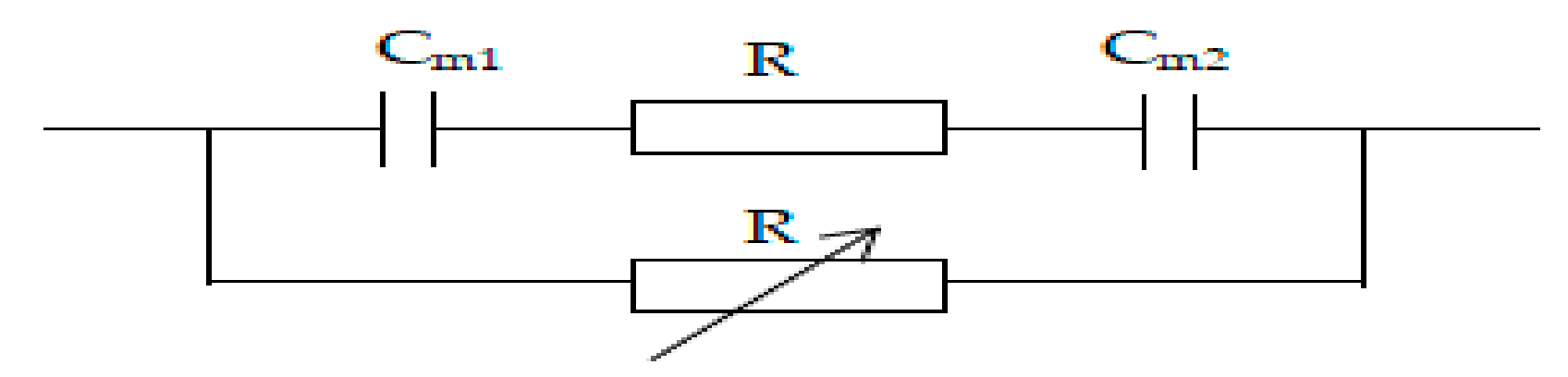
2.3.3. Membrane Area Resistance
2.3.4. Membrane Potential, Transport Number, and Selective Permittivity
2.3.5. Oxidative Stability
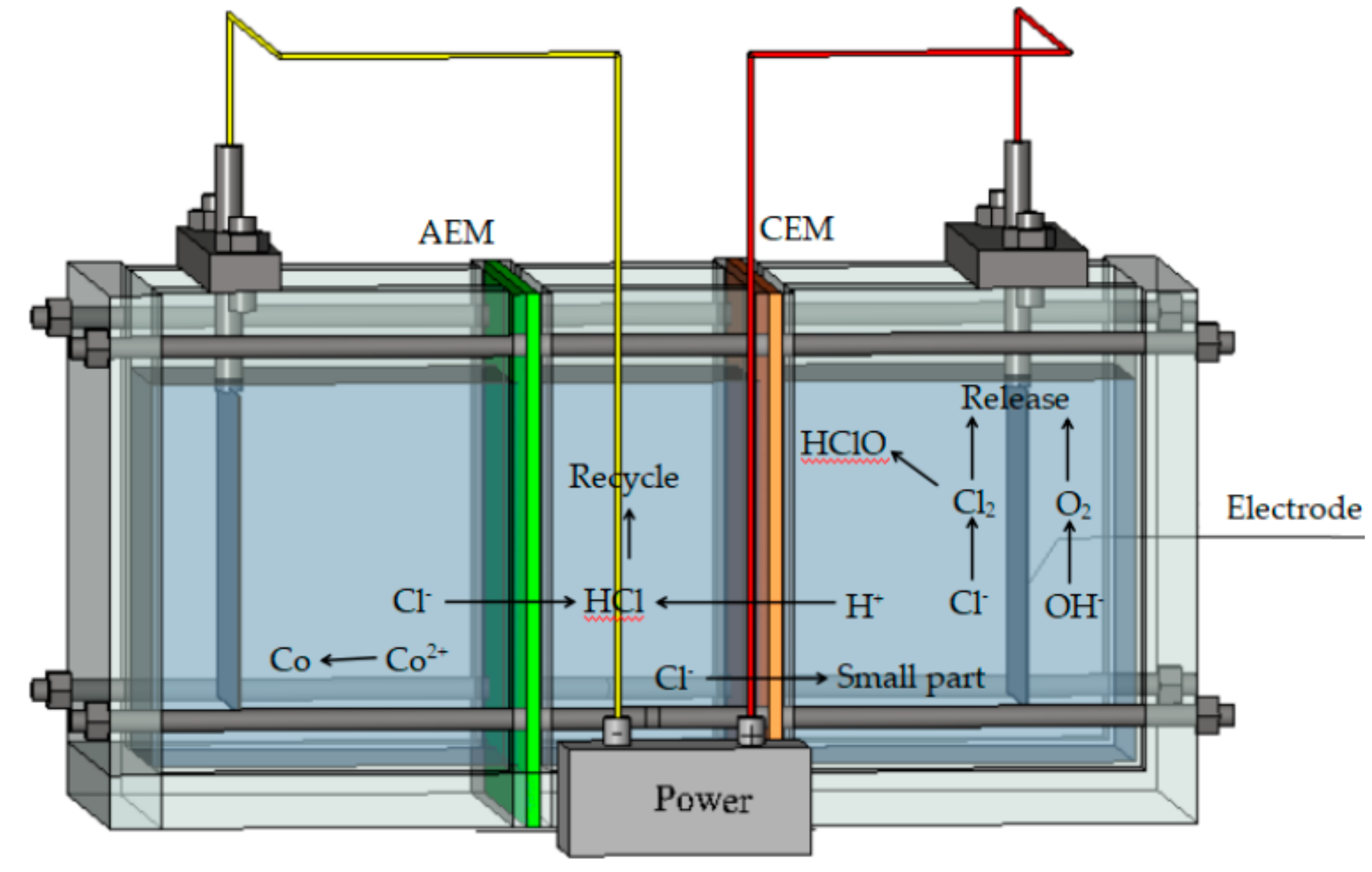
2.3.6. Treatment and Recovery of the Concentrated CoCl2 Wastewater
3. Results and Discussion
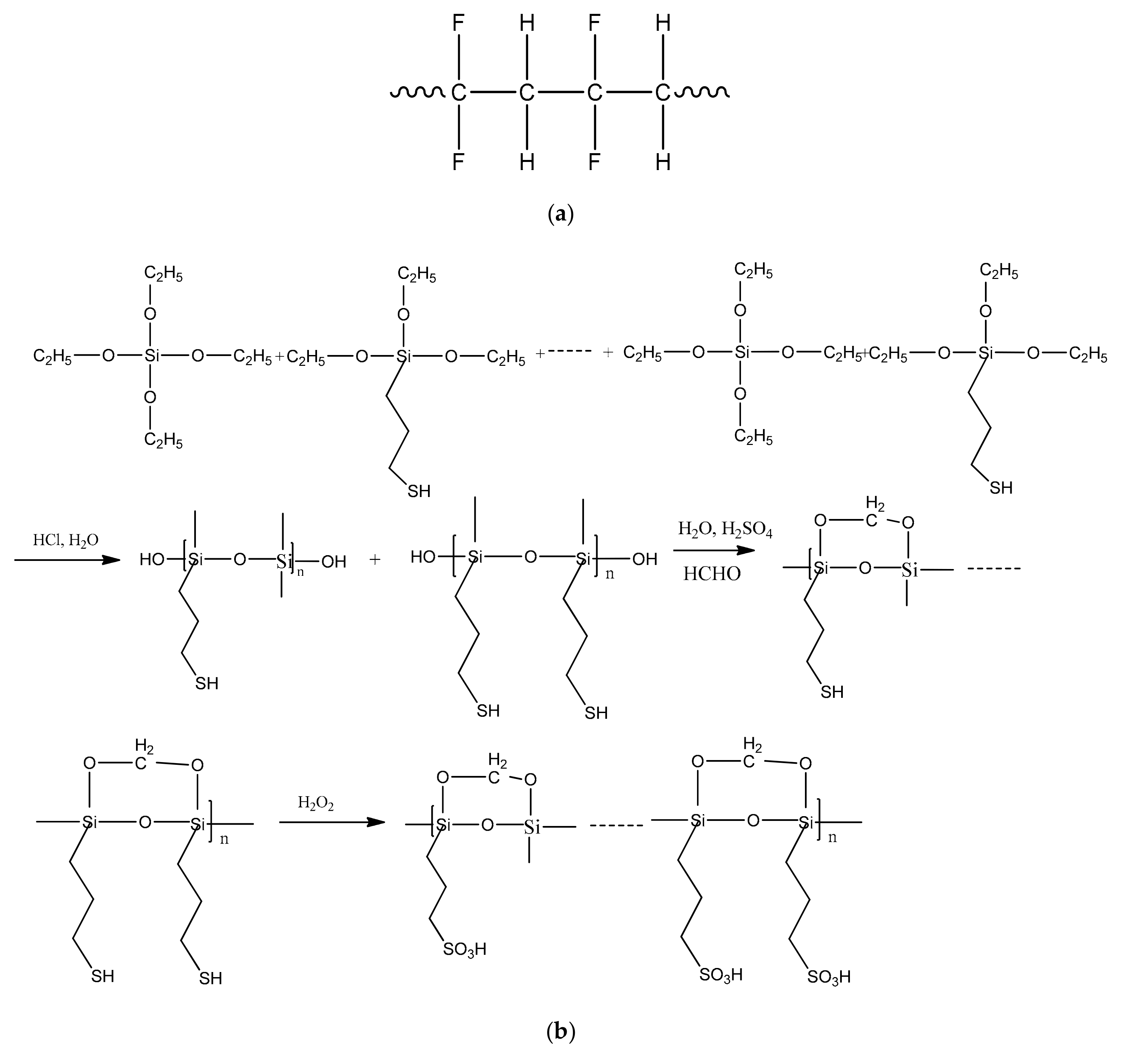
3.1. Membrane Preparation
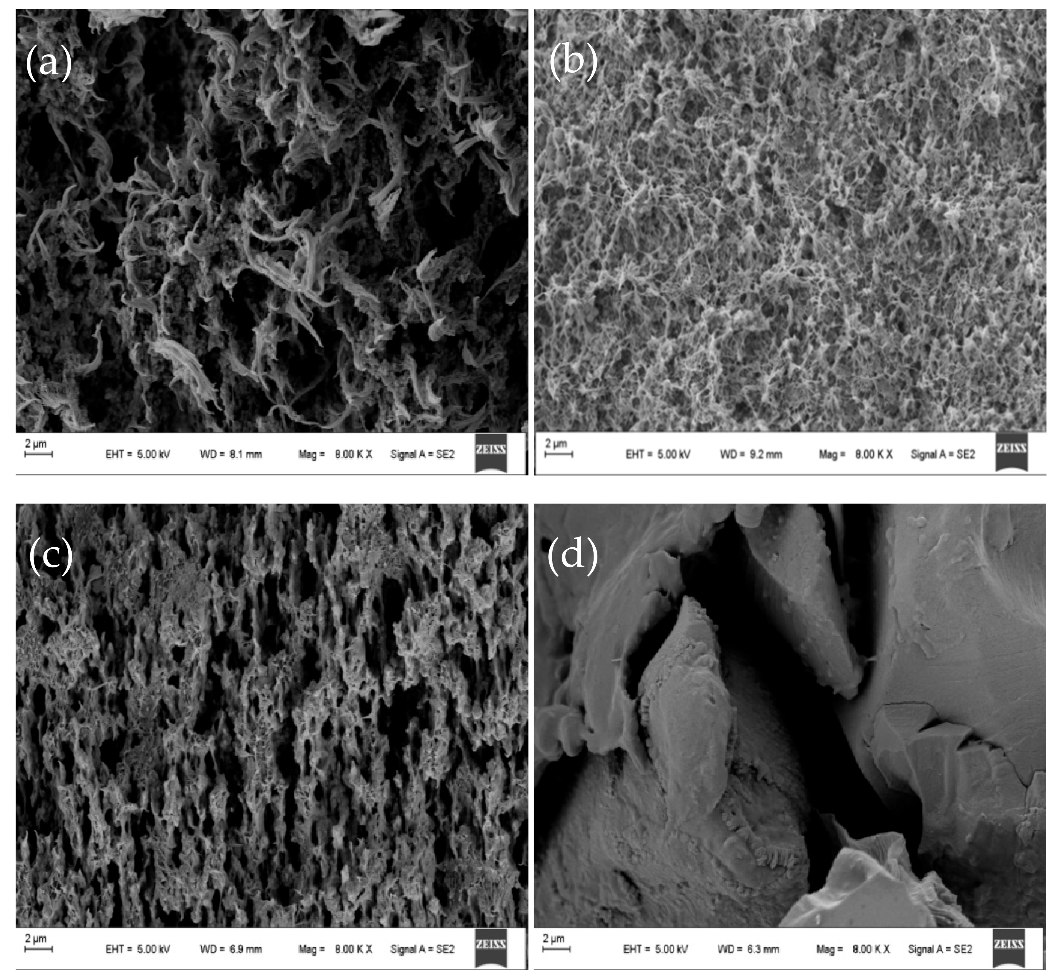
3.2. CEM Morphology
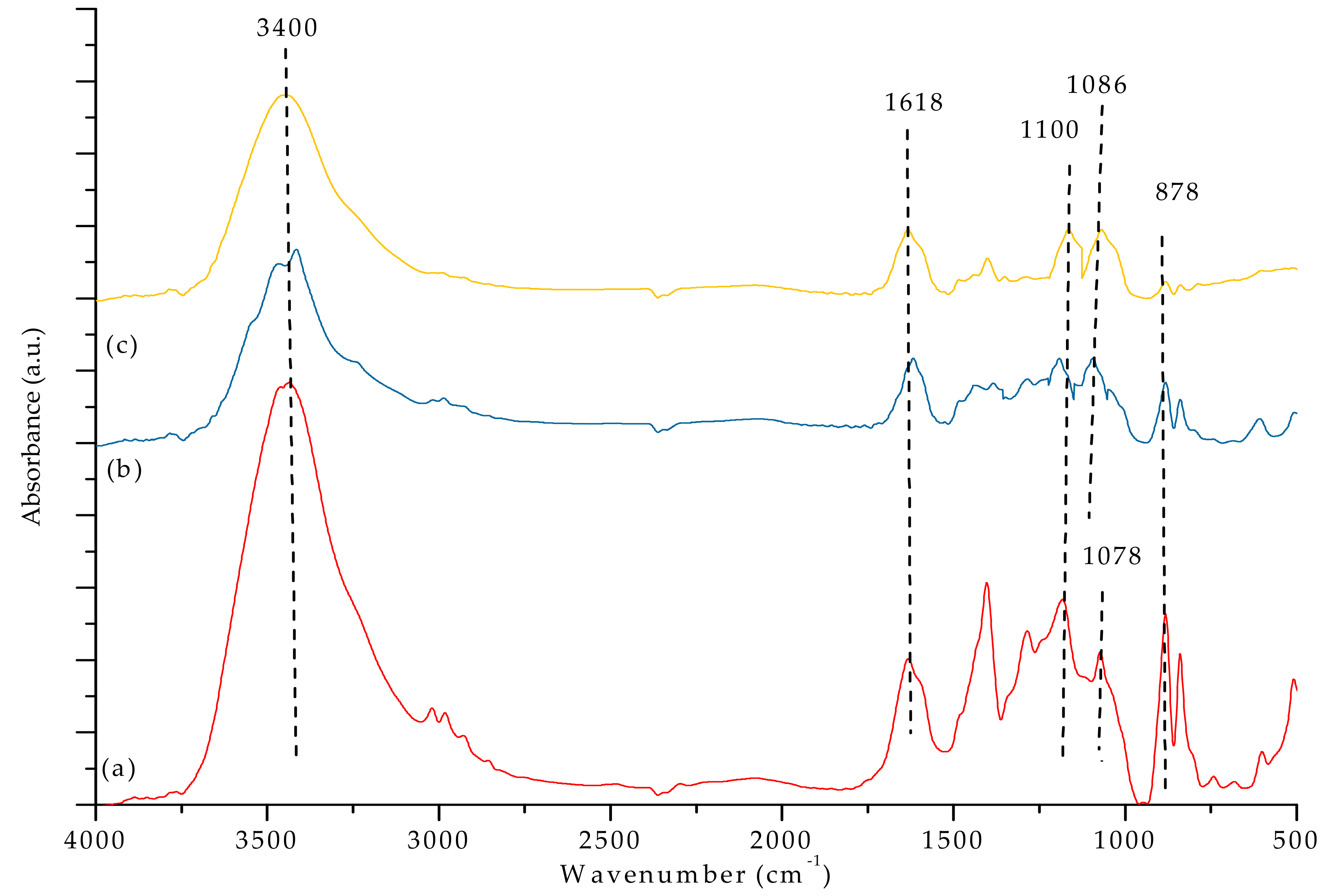
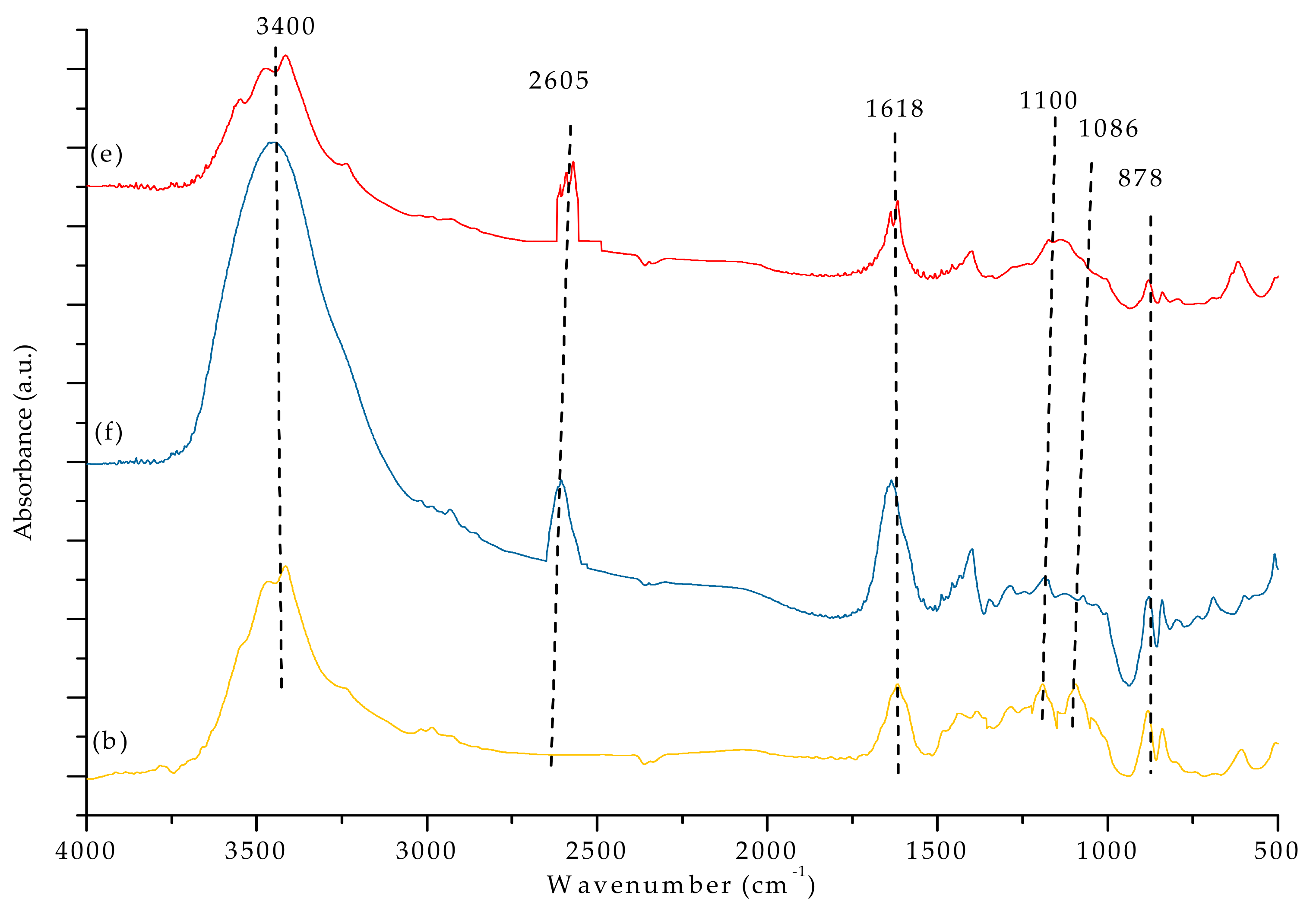
3.3. FTIR Analysis
3.4. Electrochemical Properties of CEMs
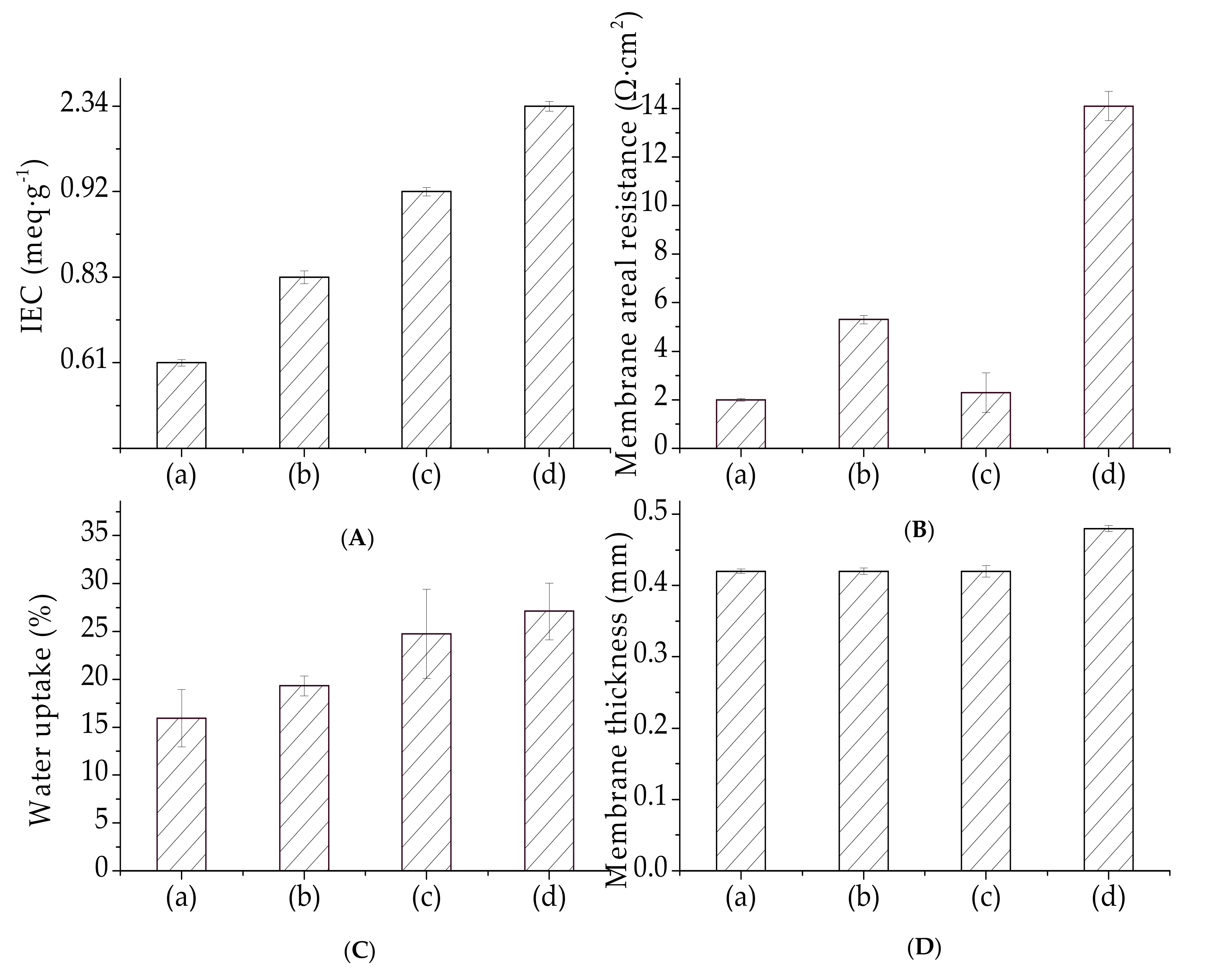
3.4.1. Ion Exchange Capacity and Water Uptake
3.4.2. Electrical Resistance
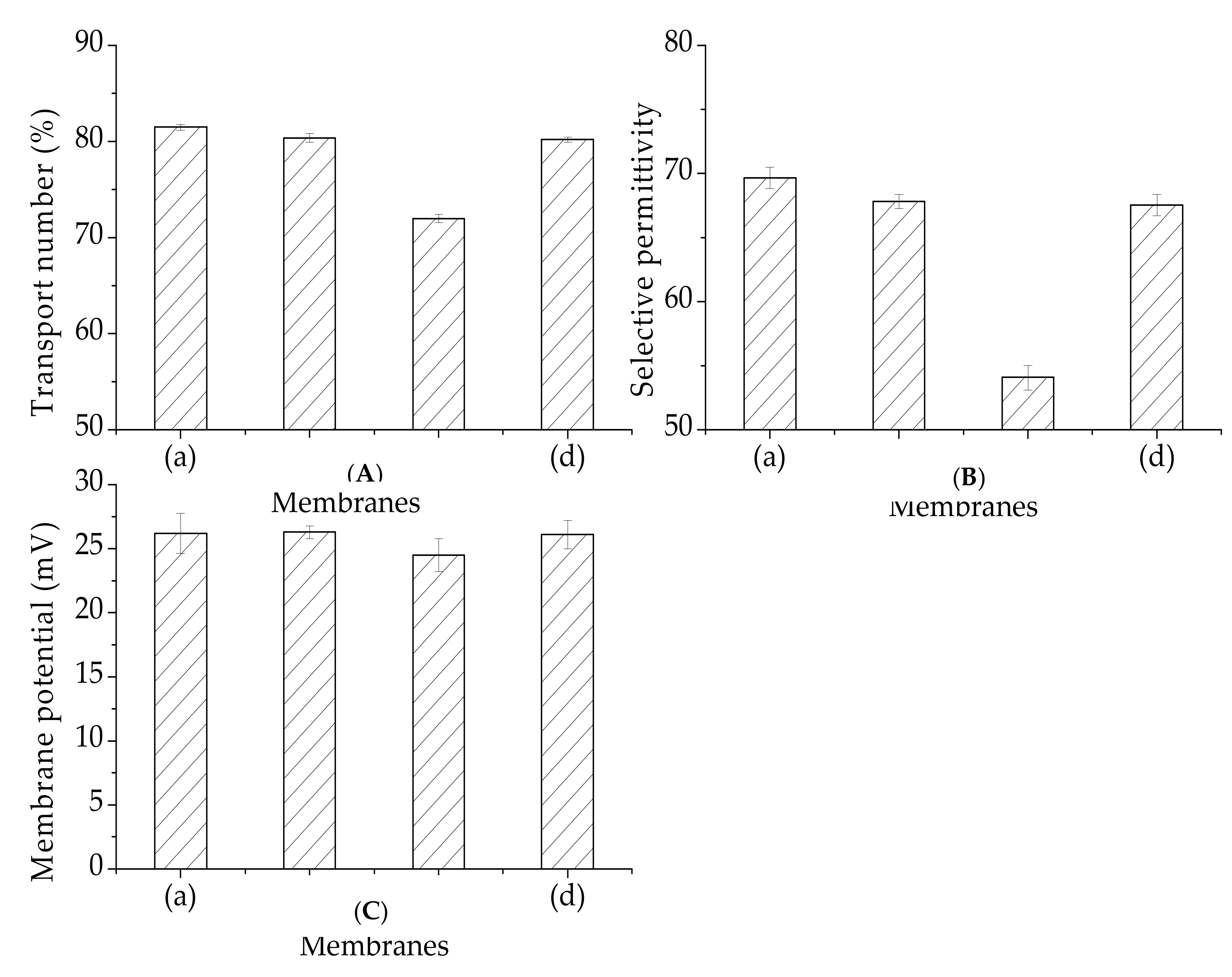
3.4.3. Membrane Potential, Transport Number, and Selective Permittivity
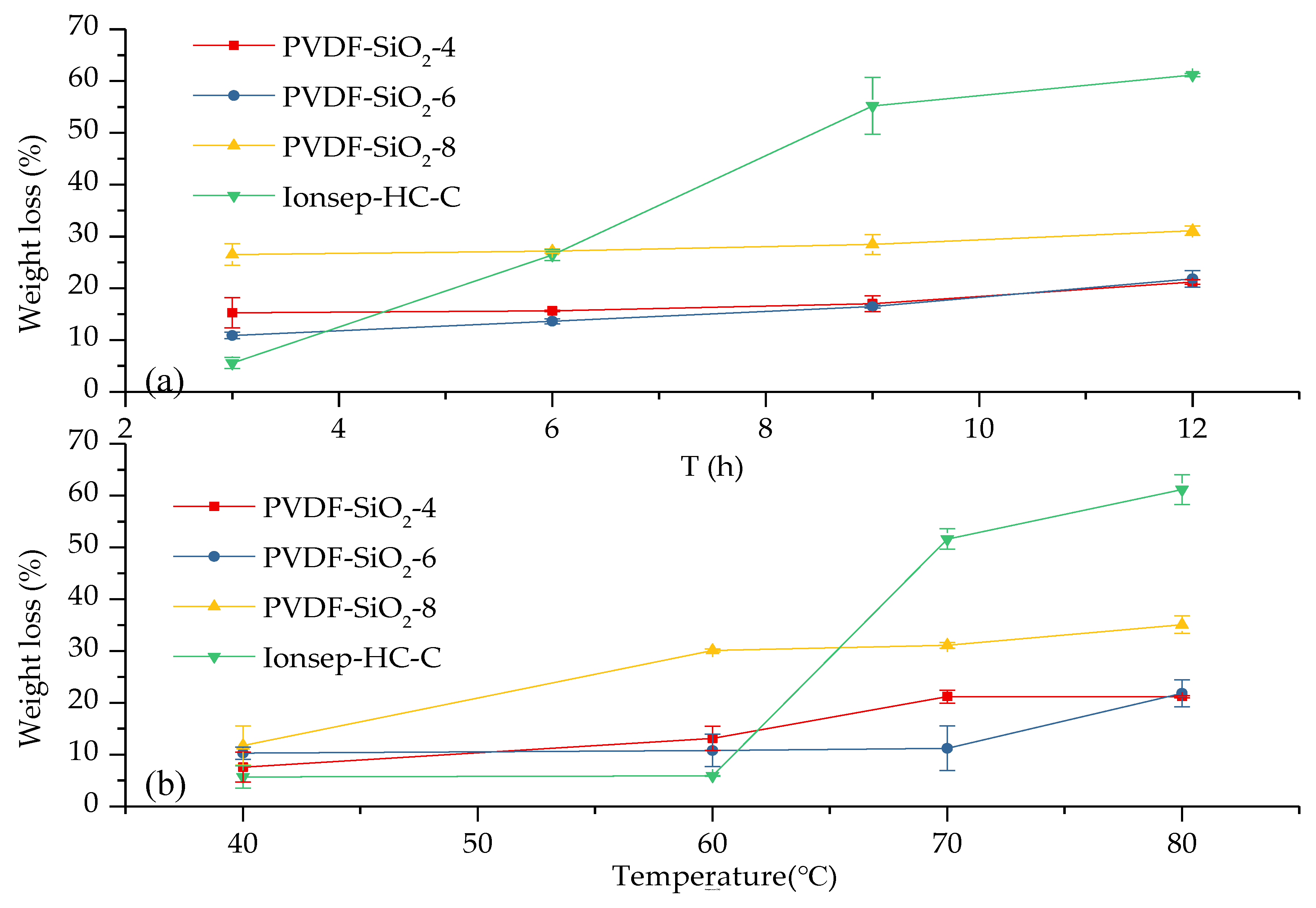
3.5. Oxidative Stability
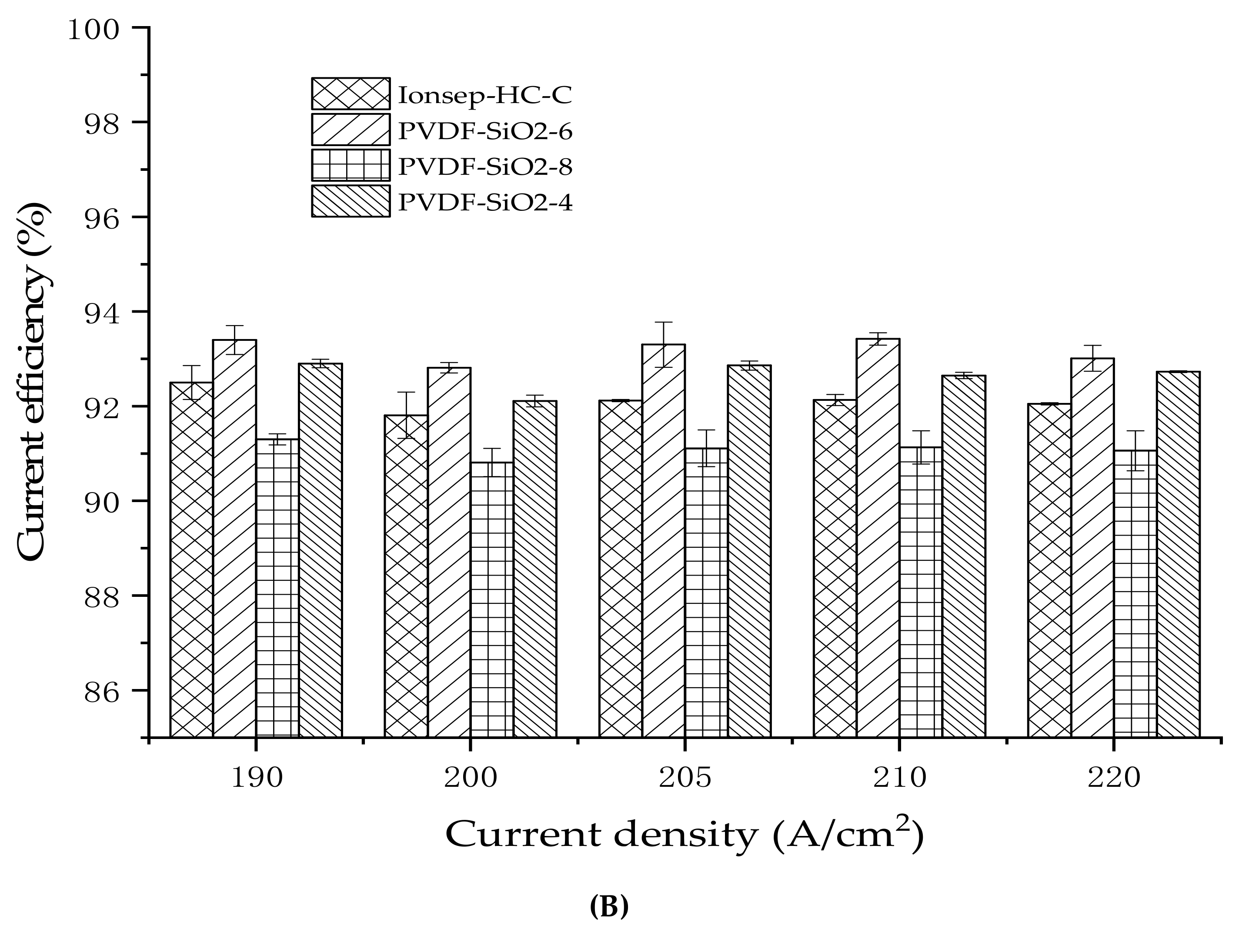
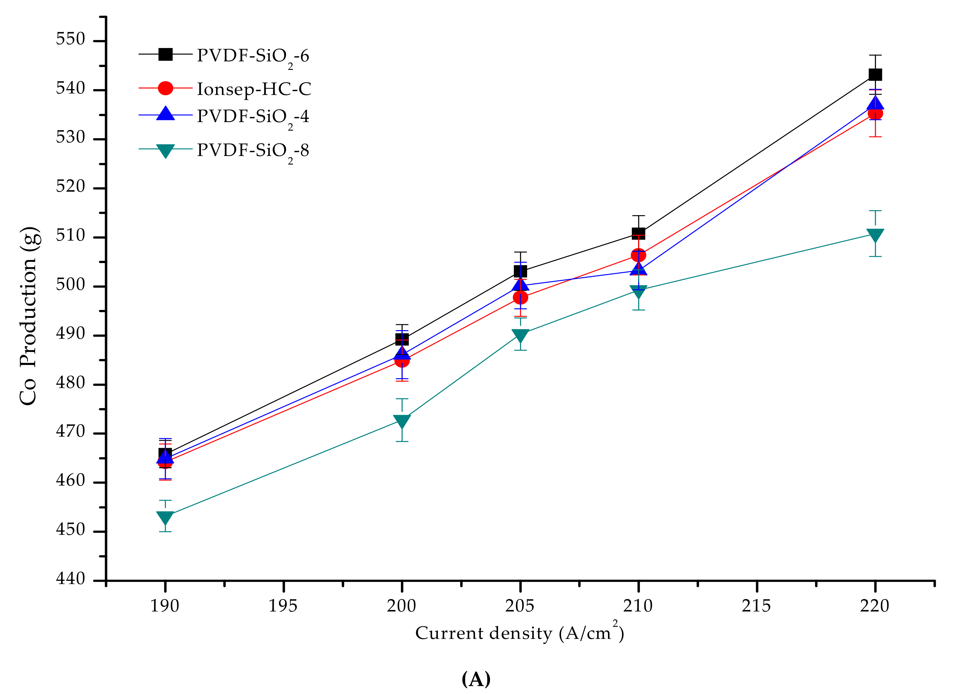
3.6. Treatment and Recovery of a High Concentration of Cobalt-Containing Wastewater
4. Conclusions
Author Contributions
Funding
Conflicts of Interest
References
- Yip, N.Y.; Elimelech, M. Comparison of Energy Efficiency and Power Density in Pressure Retarded Osmosis and Reverse Electrodialysis. Environ. Sci. Technol. 2014, 48, 11002–11012. [Google Scholar] [CrossRef]
- Kamcev, J.; Freeman, B.D. Charged Polymer Membranes for Environmental/Energy Applications. Annu. Rev. Chem. Biomol. Eng. 2016, 7, 111–133. [Google Scholar] [CrossRef] [PubMed]
- Logan, B.E.; Elimelech, M. Membrane-based processes for sustainable power generation using water. Nature 2012, 488, 313–319. [Google Scholar] [CrossRef] [PubMed]
- Yip, N.Y.; Vermaas, D.A.; Nijmeijer, K.; Elimelech, M. Thermodynamic, energy efficiency, and power density analysis ofreverse electrodialysis power generation with natural salinity gradients. Environ. Sci. Techno. 2014, 48, 4925–4936. [Google Scholar] [CrossRef] [PubMed]
- Długołȩcki, P.; Gambier, A.; Nijmeijer, K.; Wessling, M. Practical potential of reverse electrodialysis as process for sustainable energy generation. Environ. Sci. Technol. 2009, 43, 6888–6894. [Google Scholar] [CrossRef] [PubMed]
- Pilat, B. Practice of water desalination by electrodialysis. Desalination 2001, 139, 385–392. [Google Scholar] [CrossRef]
- Nagarale, R.; Gohil, G.; Shahi, V.K.; Nagarale, R. Recent developments on ion-exchange membranes and electro-membrane processes. Adv. Colloid Interface Sci. 2006, 119, 97–130. [Google Scholar] [CrossRef] [PubMed]
- Kim, Y.; Walker, W.S.; Lawler, D.F. Competitive separation of di- vs. mono-valent cations in electrodialysis: Effects of the boundary layer properties. Water Res. 2012, 46, 2042–2056. [Google Scholar] [CrossRef] [PubMed]
- Długołęcki, P.; Nymeijer, K.; Metz, S.; Wessling, M. Current status of ion exchange membranes for power generation from salinity gradients. J. Membr. Sci. 2008, 319, 214–222. [Google Scholar] [CrossRef]
- Luo, T.; Abdu, S.; Wessling, M. Selectivity of Ion Exchange Membranes: A Review. J. Membrane Sci. 2018, 429–454. [Google Scholar] [CrossRef]
- Lee, H.C.; Hong, H.S.; Kim, Y.-M.; Choi, S.H.; Hong, M.Z.; Lee, H.S.; Kim, K. Preparation and evaluation of sulfonated-fluorinated poly(arylene ether)s membranes for a proton exchange membrane fuel cell (PEMFC). Electrochimica Acta 2004, 49, 2315–2323. [Google Scholar] [CrossRef]
- Smitha, B.; Sridhar, S.; Khan, A.A. Synthesis and characterization of poly(vinyl alcohol)-based membranes for direct methanol fuel cell. J. Appl. Polym. Sci. 2010, 95, 1154–1163. [Google Scholar] [CrossRef]
- Glater, J.; Hong, S.K.; Elimelech, M. The search for a chlorine-resistant reverse os-mosis membrane. Desalination 1994, 95, 325–345. [Google Scholar] [CrossRef]
- Kang, G.-D.; Gao, C.-J.; Chen, W.-D.; Jie, X.-M.; Cao, Y.-M.; Yuan, Q. Study on hypochlorite degradation of aromatic polyamide reverse osmosis membrane. J. Membr. Sci. 2007, 300, 165–171. [Google Scholar] [CrossRef]
- Jun, B.-M.; Yun, E.-T.; Han, S.-W.; Nga, N.T.P.; Park, H.-G.; Kwon, Y.-N. Chlorine Disinfection in Water Treatment Plants and its Effects on Polyamide Membrane. Membr. J. 2014, 24, 88–99. [Google Scholar] [CrossRef]
- Kim, M.; Kim, M.; Park, B.; Kim, S. Changes in characteristics of polyamide reverse osmosis membrane due to chlorine attack. Desalin. Water Treat. 2015, 54, 923–928. [Google Scholar] [CrossRef]
- Zhang, Y.; Wang, S.; Zhou, J.; Zhang, S. Preparation and properties of SiO2-PWA/PVDF hybrid cation exchange membranes. Membrane Sci. Technol. 2018, 38, 67–73. (In Chinese) [Google Scholar]
- Siu, A.; Pivovar, B.; Horsfall, J.; Lovell, K.V.; Holdcroft, S.; Horsfall, J. Dependence of methanol permeability on the nature of water and the morphology of graft copolymer proton exchange membranes. J. Polym. Sci. Part B: Polym. Phys. 2006, 44, 2240–2252. [Google Scholar] [CrossRef]
- Jung, D.; Myoung, Y.-B.; Cho, S.-Y.; Shin, D.R.; Peck, D.H. A performance evaluation of direct methanol fuel cell using impregnated tetraethyl-orthosilicate in cross-linked polymer membrane. Int. J. Hydrogen Energy 2001, 26, 1263–1269. [Google Scholar] [CrossRef]
- Mu, Y. Study on modification of cation exchange membrane used in the process of cobalt electrowinning. Master Thesis, Lanzhou Jiaotong University, Lanzhou, China, 2014. (In Chinese). [Google Scholar]
- Nagarale, R.K.; Gohil, G.S.; Shahi, V.K.; Rangarajan, R.; Nagarale, R. Organic−Inorganic Hybrid Membrane: Thermally Stable Cation-Exchange Membrane Prepared by the Sol−Gel Method. Macromolecules 2004, 37, 10023–10030. [Google Scholar] [CrossRef]
- Cho, J.W.; Sul, K.I. Characterization and properties of hybrid composites prepared from poly(vinylidene fluoride–tetrafluoroethylene) and SiO2. Polymer 2001, 42, 727–736. [Google Scholar]
- Tsuru, T. Nano/subnano-tuning of porous ceramic membranes for molecular separation. J. Sol-Gel Sci. Technol. 2008, 46, 349–361. [Google Scholar] [CrossRef]
- Gu, Y.; Oyama, S. High Molecular Permeance in a Poreless Ceramic Membrane. Adv. Mater. 2010, 19, 1636–1640. [Google Scholar] [CrossRef]
- Pandey, J.; Shukla, A. PVDF supported silica immobilized phosphotungstic acid membrane for DMFC application. Solid State Ionics 2014, 262, 811–814. [Google Scholar] [CrossRef]
- Pandey, J.; Mir, F.Q.; Shukla, A. Performance of PVDF supported silica immobilized phosphotungstic acid membrane (Si-PWA/PVDF) in direct methanol fuel cell. Int. J. Hydrogen Energy 2014, 39, 17306–17313. [Google Scholar] [CrossRef]
- Pandey, J.; Mir, F.Q.; Shukla, A. Synthesis of silica immobilized phosphotungstic acid (Si-PWA)-poly(vinyl alcohol) (PVA) composite ion-exchange membrane for direct methanol fuel cell. Int. J. Hydrogen Energy 2014, 39, 9473–9481. [Google Scholar] [CrossRef]
- Yu, S.; Zuo, X.; Bao, R.; Xu, X.; Wang, J.; Xu, J. Effect of SiO2 nanoparticle addition on the characteristics of a new organic–inorganic hybrid membrane. Polymer 2009, 50, 553–559. [Google Scholar] [CrossRef]
- Zuo, X.; Yu, S.; Xu, X.; Bao, R.; Xu, J.; Qu, W. Preparation of organic–inorganic hybrid cation-exchange membranes via blending method and their electrochemical characterization. J. Membr. Sci. 2009, 328, 23–30. [Google Scholar] [CrossRef]
- Peng, F.; Lu, L.; Sun, H.; Wang, Y.; Liu, J.; Jiang, Z. Hybrid Organic−Inorganic Membrane: Solving the Tradeoff between Permeability and Selectivity. Chem. Mater. 2005, 17, 6790–6796. [Google Scholar] [CrossRef]
- Li, G.; Kanezashi, M.; Tsuru, T. Preparation of organic–inorganic hybrid silica membranes using organoalkoxysilanes: The effect of pendant groups. J. Membr. Sci. 2011, 379, 287–295. [Google Scholar] [CrossRef]
- Mosa, J.; Durán, A.; Aparicio, M. Sulfonic acid-functionalized hybrid organiceinorganic proton exchange membranes synthesized by solegel using 3-mercaptopropyl trimethoxysilane (MPTMS). J. Power Sources 2015, 297, 208–216. [Google Scholar] [CrossRef]
- Liu, X.; Peng, Y.; Ji, S. A new method to prepare organic–inorganic hybrid membranes. Desalination 2008, 221, 376–382. [Google Scholar] [CrossRef]
- Zhang, X.; Zhou, J.; Zou, X.; Wang, Z.; Chu, Y.; Wang, S. Preparation of Nano-SiO2/Al2O3/ZnO-Blended PVDF Cation-Exchange Membranes with Improved Membrane Permselectivity and Oxidation Stability. Materials 2018, 11, 2465. [Google Scholar] [CrossRef] [PubMed]
- Hosseini, S.; Madaeni, S.; Khodabakhshi, A.; Zendehnam, A. Preparation and surface modification of PVC/SBR heterogeneous cation exchange membrane with silver nanoparticles by plasma treatment. J. Membr. Sci. 2010, 365, 438–446. [Google Scholar] [CrossRef]
- Hosseini, S.; Madaeni, S.; Khodabakhshi, A. Preparation and characterization of ABS/HIPS heterogeneous cation exchange membranes with various blend ratios of polymer binder. J. Membr. Sci. 2010, 351, 178–188. [Google Scholar] [CrossRef]
- Hosseini, S.M.; Madaeni, S.S.; Khodabakhshi, A.R. Preparation and characteriza-tion of PC/SBR heterogeneous cation exchange membrane filled with carbon nano-tubes. J. Membr. Sci. 2010, 362, 550–559. [Google Scholar] [CrossRef]
- Nagarale, R.; Shahi, V.K.; Thampy, S.; Rangarajan, R.; Nagarale, R. Studies on electrochemical characterization of polycarbonate and polysulfone based heterogeneous cation-exchange membranes. React. Funct. Polym. 2004, 61, 131–138. [Google Scholar] [CrossRef]
- Shahi, V.; Thampy, S.; Rangarajan, R. Studies on transport properties of surfactant immobilized anion-exchange membrane. J. Membr. Sci. 1999, 158, 77–83. [Google Scholar] [CrossRef]
- Nagarale, R.; Gohil, G.; Shahi, V.K.; Rangarajan, R.; Nagarale, R. Preparation and electrochemical characterizations of cation-exchange membranes with different functional groups. Colloids Surfaces A: Physicochem. Eng. Asp. 2004, 251, 133–140. [Google Scholar] [CrossRef]
- Livage, J. Sol-gel synthesis of hybrid materials. Bull. Mater. Sci. 1999, 22, 201–205. [Google Scholar] [CrossRef]
- Sata, T.; Wang, M.; Ren, Q.C. Ion exchange membranes: preparation, characterization, modification and application; Chemical Industry Press: Beijing, China, 2015. (In Chinese) [Google Scholar]
- Feng, S.; Shang, Y.; Wang, Y.; Xie, X.; Mathur, V.; Xu, J. Organic–inorganic crosslinked and hybrid membranes derived from sulfonated poly(arylene ether sulfone)/silica via sol–gel process. J. Power Sources 2010, 195, 2541–2548. [Google Scholar] [CrossRef]
- Zhang, H. Modern Organic Spectral Analysis; Chemical Industry Press Textbook Publishing Center: Beijing, China, 2005; pp. 260–289. [Google Scholar]
- Yin, J.; Zhou, J. Novel polyethersulfone hybrid ultrafiltration membrane prepared with SiO2-g-(PDMAEMA-co-PDMAPS) and its antifouling performances in oil-in-water emulsion application. Desalination 2015, 365, 46–56. [Google Scholar] [CrossRef]
- Hübner, G.; Roduner, E. EPR investigation of HO/ radical initiated degradation reactions of sulfonated aromatics as model compounds for fuel cell proton conducting membranes. J. Mater. Chem. 1999, 9, 409–418. [Google Scholar] [CrossRef]
- Zhang, L.; Mukherjee, S. Investigation of durability issues of selected non-fluorinated polymer exchange membranes for fuel cell application. J. Elcetrochem. Soc. 2006, 153, A1062–A1072. [Google Scholar] [CrossRef]
- Smitha, B.; Sridhar, S.; Khan, A.A. Polyelectrolyte Complexes of Chitosan and Poly(acrylic acid) As Proton Exchange Membranes for Fuel Cells. Macromolecules 2004, 37, 2233–2239. [Google Scholar] [CrossRef]
- Peng, C.; Chen, G. Preparation and Assessment of Heat-Treated α-Chitin Nanowhiskers Reinforced Poly(viny alcohol) Film for Packaging Application. Materials 2018, 11, 1883. [Google Scholar] [CrossRef] [PubMed]
- Ke, H.; Li, Y. The Effects of Using Aluminum Oxide Nanoparticles as Heat Transfer Fillers on Morphology and Thermal Performances of Form-Stable Phase Change Fibrous Membranes Based on Capric–Palmitic–Stearic Acid Ternary Eutectic/Polyacrylonitrile Composite. Materials 2018, 11, 1785. [Google Scholar] [CrossRef]
- Zhong, S.; Cui, X.; Cai, H.; Fu, T.; Zhao, C.; Na, H. Crosslinked sulfonated poly(ether ether ketone) proton exchange membranes for direct methanol fuel cell applications. J. Power Sources 2007, 164, 65–72. [Google Scholar] [CrossRef]
- Siracusano, S.; Trocino, S.; Briguglio, N.; Baglio, V.; Aricò, A.S. Electrochemical Impedance Spectroscopy as a Diagnostic Tool in Polymer Electrolyte Membrane Electrolysis. Materials 2018, 11, 1368. [Google Scholar] [CrossRef]
- Nagarale, R.; Gohil, G.; Shahi, V.K.; Trivedi, G.; Rangarajan, R.; Nagarale, R. Preparation and electrochemical characterization of cation- and anion-exchange/polyaniline composite membranes. J. Colloid Interface Sci. 2004, 277, 162–171. [Google Scholar] [CrossRef]
- Okada, T.; Xie, G.; Meeg, M. Simulation for water management in membranes for polymer electrolyte fuel cells. Electrochimica Acta 1998, 43, 2141–2155. [Google Scholar] [CrossRef]
- Li, K.-D.; Chen, P.-W.; Chang, K.-S.; Hsu, S.-C.; Jan, D.-J. Indium-Zinc-Tin-Oxide Film Prepared by Reactive Magnetron Sputtering for Electrochromic Applications. Materials 2018, 11, 2221. [Google Scholar] [CrossRef] [PubMed]
- Zabolotsky, V.I.; Nikonenko, V.V. Effect of structural membrane in homogeneity on transport properties. J. Membr. Sci. 1993, 79, 181–191. [Google Scholar] [CrossRef]


© 2019 by the authors. Licensee MDPI, Basel, Switzerland. This article is an open access article distributed under the terms and conditions of the Creative Commons Attribution (CC BY) license (http://creativecommons.org/licenses/by/4.0/).
Share and Cite
Li, Y.; Li, Z.; Li, Y.; Guan, W.; Zheng, Y.; Zhang, X.; Wang, S. Preparation and Electrochemical Characterization of Organic–Inorganic Hybrid Poly(Vinylidene Fluoride)-SiO2 Cation-Exchange Membranes by the Sol-Gel Method Using 3-Mercapto-Propyl-Triethoxyl-Silane. Materials 2019, 12, 3265. https://doi.org/10.3390/ma12193265
Li Y, Li Z, Li Y, Guan W, Zheng Y, Zhang X, Wang S. Preparation and Electrochemical Characterization of Organic–Inorganic Hybrid Poly(Vinylidene Fluoride)-SiO2 Cation-Exchange Membranes by the Sol-Gel Method Using 3-Mercapto-Propyl-Triethoxyl-Silane. Materials. 2019; 12(19):3265. https://doi.org/10.3390/ma12193265
Chicago/Turabian StyleLi, Yanhong, Zhiwei Li, Yanjuan Li, Wenxue Guan, Yangyang Zheng, Xuemin Zhang, and Sanfan Wang. 2019. "Preparation and Electrochemical Characterization of Organic–Inorganic Hybrid Poly(Vinylidene Fluoride)-SiO2 Cation-Exchange Membranes by the Sol-Gel Method Using 3-Mercapto-Propyl-Triethoxyl-Silane" Materials 12, no. 19: 3265. https://doi.org/10.3390/ma12193265
APA StyleLi, Y., Li, Z., Li, Y., Guan, W., Zheng, Y., Zhang, X., & Wang, S. (2019). Preparation and Electrochemical Characterization of Organic–Inorganic Hybrid Poly(Vinylidene Fluoride)-SiO2 Cation-Exchange Membranes by the Sol-Gel Method Using 3-Mercapto-Propyl-Triethoxyl-Silane. Materials, 12(19), 3265. https://doi.org/10.3390/ma12193265