Article

Interfacial Reactions and Mechanical Properties Studies of C-Coated and C/B4C Duplex-Coated SiC Fiber-Reinforced Ti2AlNb Composites

1
State Key Laboratory of Metastable Materials Science and Technology, Yanshan University, Qinhuangdao 066004, China
2
AECC Beijing Institute of Aeronautical Materials, P.O.Box: 81-15, Beijing 100095, China
3
State Key Laboratory of Superhard Materials, Department of Materials Science, Key Laboratory of Automobile Materials, MOE, Jilin University, Changchun 130012, China
*
Authors to whom correspondence should be addressed.
Materials 2019, 12(19), 3257; https://doi.org/10.3390/ma12193257
Submission received: 22 August 2019 / Revised: 1 October 2019 / Accepted: 3 October 2019 / Published: 6 October 2019
(This article belongs to the Section Advanced Composites)

Abstract

:
Continuous SiC fiber-reinforced Ti2AlNb matrix composites have a great potential for high-temperature aviation structure applications, and their properties strongly depend on the microstructure of the interfacial reaction layer. Notably, introducing diffusion barrier coatings has still been a popular strategy for optimizing the interfacial structure and interfacial properties of SiCf/Ti. In this work, C coating and C/B4C duplex coating were successfully fabricated onto SiC fibers via chemical vapor deposition (CVD), then consolidated into the SiCf/C/Ti2AlNb and the SiCf/C/B4C/Ti2AlNb composites, respectively, via hot isostatic pressing (HIP) under the condition of 970 °C, 150 MPa, 120 min, and finally furnace cooled to room temperature. The C- and C/B4C-dominated interfacial reactions in the SiCf/C/Ti2AlNb and the SiCf/C/B4C/Ti2AlNb were explored, revealing two different reaction products sequences: The different-sized TiC and the coarse-grained (Ti,Nb)C + AlNb3 for the SiCf/C/Ti2AlNb; and the fine-grained TiB2 + TiC, the needle-shaped (Ti,Nb)B2/NbB + (Ti,Nb)C, the coarse-grained (Ti,Nb)C + AlNb2 for the SiCf/C/B4C/Ti2AlNb. Annealing experiments were further carried out to verify the different reaction kinetics caused by C coating and C/B4C duplex coating. The reaction layer (RL)-dominated interfacial strength and tensile strength estimations showed that higher interface strength and tensile strength occurred in the SiCf/C/Ti2AlNb instead of the SiCf/C/B4C/Ti2AlNb, when the same failure mode of fiber push-out took place.

1. Introduction

Continuous SiC fiber-reinforced titanium matrix composites (SiCf/Ti) have been considered as one of most potential light-weight high-strength structural materials required by aerospace vehicles and advanced propulsion system, due to their high specific strength and stiffness at both room and elevated temperature [1,2,3]. The physical and mechanical properties of several materials for potential applications in the aero-engine field are shown in Table 1 [4]. And the specific strength and stiffness at room and elevated temperatures of several composites are shown in Figure 1 [5]. Raising the service temperature of SiCf/Ti is a continuous pursuit driven by many new applications. Recently, intermetallic titanium aluminides (TiAl, Ti3Al, Ti2AlNb) have begun to be employed as the matrix of SiCf/Ti due to their more excellent high temperature performance, as compared with common Ti alloys [6,7]. Among them, Ti2AlNb alloys with higher ductility and formability have attracted more attention due to their excellent low- and high-temperature loading capabilities [7,8,9,10]. Therefore, Ti2AlNb alloys, especially with O-phase as the main component that contributes a superior ductility [10], would be the potential choice for the development of high-temperature titanium matrix composites (TMCs) [11,12]. Smith et al. fabricated the SCS-6 SiCf/Ti2AlNb by foil–fiber–foil processing (FFF) and identified the interfacial products consisting of TiC1-x+Ti5Si3, (Ti,Nb,Si)C1–x, Al(Ti,Nb)3C and (Ti,Nb,Al)5(Si,Al)3, with the primary reaction zone size of ~0.6 μm; the SiCf/Ti2AlNb exhibited more excellent high temperature performance compared to SiCf2-Ti and the longitudinal tensile properties of the composite (which are dominated by the fiber strength) were slightly improved due to the orthorhombic matrix. [13]. Luo et al. further introduced C/Mo duplex coatings as barrier layers and prepared the SiCf/C/Mo/Ti2AlNb by the FFF method. They found that the Mo barrier layer can regulate the microstructure of the matrix by forming a B2-riched transition zone between the reaction layer (RL) and the matrix in the SiCf/Ti-21Al-29Nb composite, obtaining a higher tensile strength relative to the Ti2AlNb alloy [14]. In addition, Yang et al. employed a matrix-coated fiber (MCF) method to fabricate SCS-6 SiCf/Ti2AlNb, and also explored the interfacial reactions between SCS-6 SiC fiber and Ti2AlNb, showing a milder interfacial reaction than that in SiCf/super α2-Ti (Ti-25Al-10Nb-3V-1Mo) [15]. Compared with other Ti alloys matrices (Ti-6Al-4V, TC17, IMI834) [5,16,17], Ti2AlNb acting as the matrix can exactly elevate the service temperature of SiCf/Ti. However, the SiCf/Ti2AlNb is still inadequately understood, especially for the reason that the interfacial reactions of SiCf/Ti2AlNb are sensitive to the type of diffusion barrier coating, the microstructure of the matrix, the consolidation process, etc.
It is accepted that the interfacial reactions (mainly including interfacial products and their distribution, and each sub-layer thickness) of SiCf/Ti would determine the interfacial properties, and further act on the performances of SiCf/Ti [2,18]. Accordingly, understanding and further tailoring the interfacial behaviors of SiCf/Ti2AlNb would be necessary to ensure its superior properties. Notably, introducing diffusion barrier coatings is still a popular strategy for optimizing the interfacial structure and interfacial properties of SiCf/Ti, which can not only protect the SiC fiber suffering from the attack from the matrix, but also obtain a moderate interfacial debonding strength arising from the formation of an appropriate interfacial reaction layer. Several potential diffusion barrier coatings, including carbon, carbides, borides, oxides, nitrides, and transition metals, have been investigated to protect SiC fiber and control the interfacial reactions of SiCf/Ti [19,20,21,22,23]. Among them, C coating is still the most widely used diffusion barrier coatings in the SiCf/Ti [24,25]. In addition to protecting the SiC fiber, the C coating has the following advantages: (1) It has a good thermal expansion coefficient with SiC fiber; (2) it has a good compatibility with SiC; (3) the interface reaction of composites is easy to control; and (4) the process stability is good. The interfacial reactions between SCS-6 SiC fiber and Ti2AlNb have been well explored, when the SCS-6 SiC fiber is comprised of surface C coating with some SiC particles in it [15]. However, the interfacial reactions between pure C coating and Ti2AlNb matrix are still unclear. In addition, Zhang et al. found that as B4C coating was introduced to SiCf/TiAl as the diffusion barrier coating, a thin interfacial layer appeared, confirming the role of B4C coating in serving as a potential barrier coating in the SiCf/TiAl [26]. Obviously, both C and B4C are two potential diffusion barrier coatings in the SiCf/Ti2AlNb. A comparative study on the interfacial reactions of SiCf/Ti2AlNb with C and B4C diffusion barrier coatings would; thus, be helpful to understand their interfacial behaviors.
In the present paper, C coating and C/B4C duplex coatings were, respectively, prepared on SiC fibers by chemical vapor deposition (CVD) as different diffusion barrier layers, Then two kinds of SiCf/C/Ti2AlNb and SiCf/C/B4C/Ti2AlNb composites were successfully fabricated by MCF method and hot isostatic pressing (HIP) consolidation. Finally, C and C/B4C diffusion barrier layer-dominated interfacial reactions, matrix microstructure evolutions, interfacial debonding strength, and tensile strength were investigated.

2. Materials and Methods

2.1. Sample Preparation

C-coated and C/B4C-coated SiC fibers about 100 μm in diameter (provided by AECC Beijing Institute of Aeronautical Materials, Beijing, China) were prepared by CVD. MCF method was employed to fabricate Ti2AlNb coatings onto tungsten-cored SiC monofilament as precursor wires in a facing-targets magnetron-sputtering system, with the Ti2AlNb alloy (nominal composition in at.% of Ti-22Al-25Nb) utilized as targets and the coated SiC fibers used as substrates. Next, these precursor wires were put into a Ti2AlNb alloy canister hermetically, which was then sealed using electron beam welding. Subsequently, the SiCf/Ti2AlNb was manufactured by consolidating those packed precursor wires through HIP under the soaking temperature, pressure, holding-time conditions of 970 °C, 150 MPa, 120 min, respectively, and then furnace cooled to the room temperature. This group of HIP process parameters is based on previous research [27]. With this process employed, the composite material can be completely closed, the diffusion barrier coating remains unfailing, and the RL will not be too intense. Clearly, after HIP, two composites evolving from C-coated and C/B4C-coated SiC fibers were named as SiCf/C/Ti2AlNb and SiCf/C/B4C/Ti2AlNb, respectively.

2.2. Characterization

The sectional morphology and chemical binding state of C and C/B4C coatings on SiC fibers were analyzed respectively by scanning electron microscope (SEM, FEI nano 450, Hillsboro, OR, USA), as well as ESCALAB-250 X-ray photoelectron spectrum (XPS, Waltham, MA, USA) using Al Ka radiation as the X-ray source with an energy of 1 keV. The consolidated composite specimens designated for microstructural observation by SEM were cut along the cross-section, polished, and etched in a 10% HF + 30% HNO3 solution. Specimens for transmission electron microscope (TEM) observation were cut from the composites in two directions, perpendicular to the cross-section and in the radial direction of the fiber, by FEI Quanta 200 FEG focused ion beam milling (FIB, Hillsboro, OR, USA) [28]. The interfacial reaction products were investigated by field emission JEOL 2010F TEM (Tokyo, Japan,) and the chemical compositions of the sub-layer in interfacial zones were further examined by energy-dispersive X-ray spectrometer (EDS) equipped in TEM. In order to study the kinetics of interfacial reaction, the composite samples were heat treated in vacuum at 800, 850, 900, and 950 °C for 36, 64, 100, 144, and 196 h, respectively. The total thickness of RL for these heat treatment samples was measured by SEM. Nanoindenter (Nano Test Xtreme, Micro Materials, Wrexham, UK) was employed to evaluate the interfacial debonding strength via fiber push-out test with the sample slices with 0.35 ± 0.01 mm thickness [29]. Two tensile samples were prepared for each HIP consolidated specimen with the gauge dimensions of Φ3 × M6, as shown in Figure 2, and the composite material inside the tensile specimen was ~2.8 mm in diameter. The room temperature tensile tests were performed at an extension rate of 1 mm/min, using the Inspekt Table 100 kN model universal testing machine. The fractographies were observed by SEM and laser scanning confocal microscope (LSCM, KEYENCE VK-100, Osaka, Japan).

3. Results and Discussion

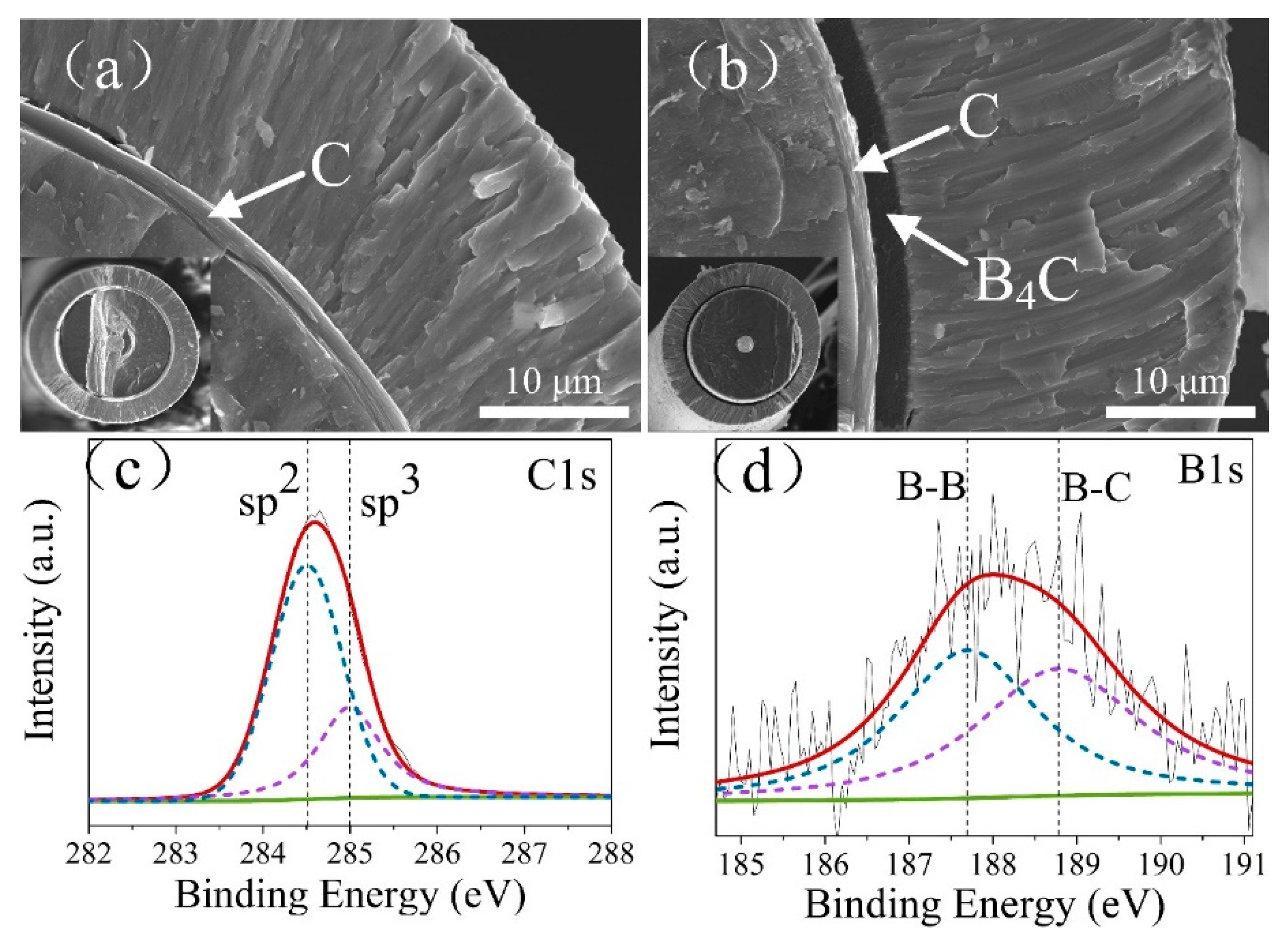
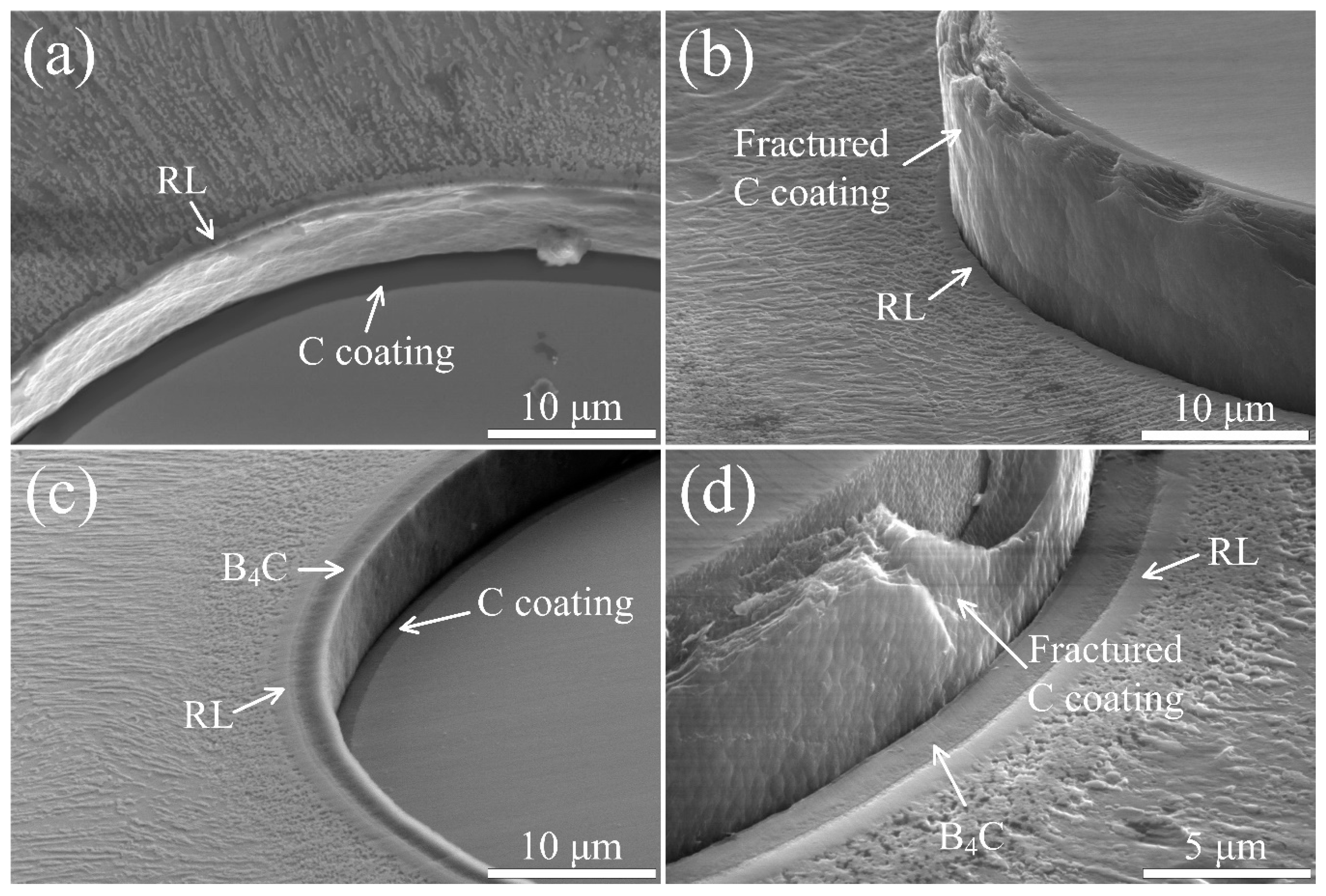
3.1. Microstructure of C and C/B4C Coatings

As expected, C coating and C/B4C duplex coating were successfully fabricated on SiC fibers by CVD. The results of SEM (Figure 3a,b) reveal that the uniform-thickness C single coating and the C/B4C duplex coating can be clearly identified and were located between SiC fibers and Ti2AlNb matrix coatings. It is noted that the thickness of C single coating was ~1.5 μm, which was almost the same as the C layer-thickness in the C/B4C duplex coating, and the total thickness of the C/B4C duplex coating approached ~3.5 μm. The ~20 μm thickness Ti2AlNb coatings on both barrier coatings are clearly visible, which were deposited by PVD process and would evolve into the matrix during consolidation. The morphologies of the two composites after consolidation are shown in Figure 4. XPS was further used to investigate the chemical binding of the C and B4C coatings. For C coating, the XPS C 1s spectrum is presented in Figure 3c, which could be deconvoluted into two peaks located at ~284.5 and ~285.0 eV, corresponding to sp2-hybridized and sp3-hybridized carbon, respectively. As suggested by the following high-resolution TEM (HRTEM) in Figure 5ⅰ, the C coating was a typical pyrolytic carbon exhibiting a turbostratic carbon structure in nature. This structure consists of small basic structural units (BSUs) mainly comprising nanoscale few-layer graphene planes. Thus, the sp2-hybridized carbon should come from graphene planes in BSUs of the C coating [16]. In contrast, the sp3 peak should be assigned to defects in graphene planes or the amorphous region in pyrolytic carbon due to its nature of high-density defects [30,31]. The integral area ratio of sp2 and sp2 + sp3 was calculated to be 76.0%, which suggested that the C coating exists mainly in the form of sp2-hybridized graphene planes in BSUs and still possess high-density defects in graphene planes. For B4C coating, the XPS B 1s spectrum is shown in Figure 3d, and the deconvolution revealed the existence of two boron chemical states at the binding energies of 187.7 and 188.8 eV, corresponding to the B–B and B–C bonds, respectively [32]. This suggests that the B4C coating still possesses a large amount of B–B bonds.
HRTEM and selected-area electron diffraction (SAED) were further used to analyze the microstructure of C and B4C coatings, which are shown in Figure 5ⅰ and Figure 6ⅰ, respectively. It reveals that C coatings exhibited a typical turbostratic carbon structure with a certain degree of tortuosity in lattice fringes, in which BSUs contained seven to eight layers (d space: 0.368 nm) as marked in the HRTEM. According to the model proposed by Reznik et al., the SAED patterns further suggested the formation of high-texture carbon by the appearance of orientation angle (OA) of 47° [33,34]. In contrast, the B4C coating exhibited a typical polycrystalline structure with the random B4C nano-particles (~10 nm in average grain size) surrounded by a small amount of amorphous phases, as revealed by the HRTEM images and corresponding SAED in Figure 6ⅰ.

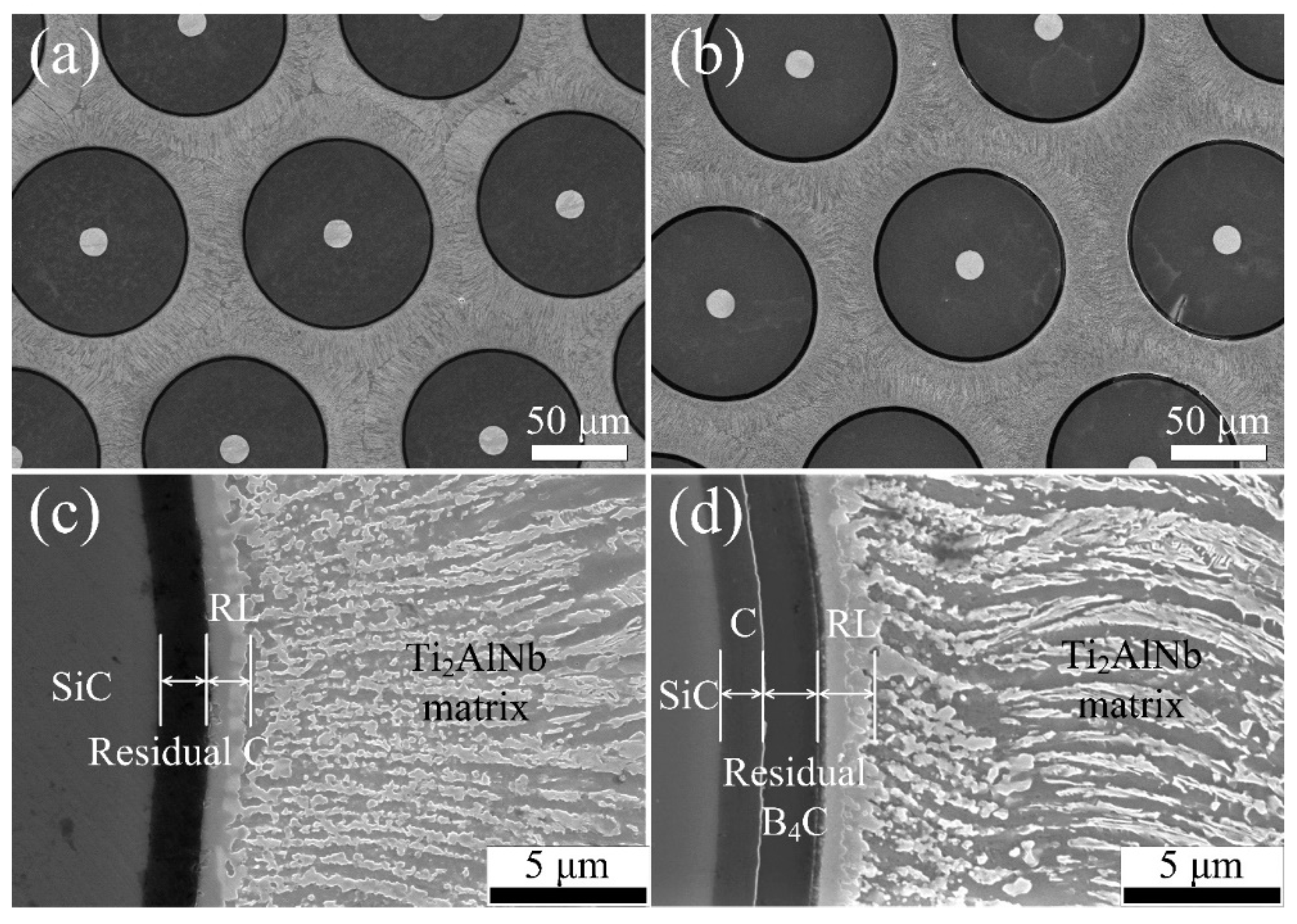
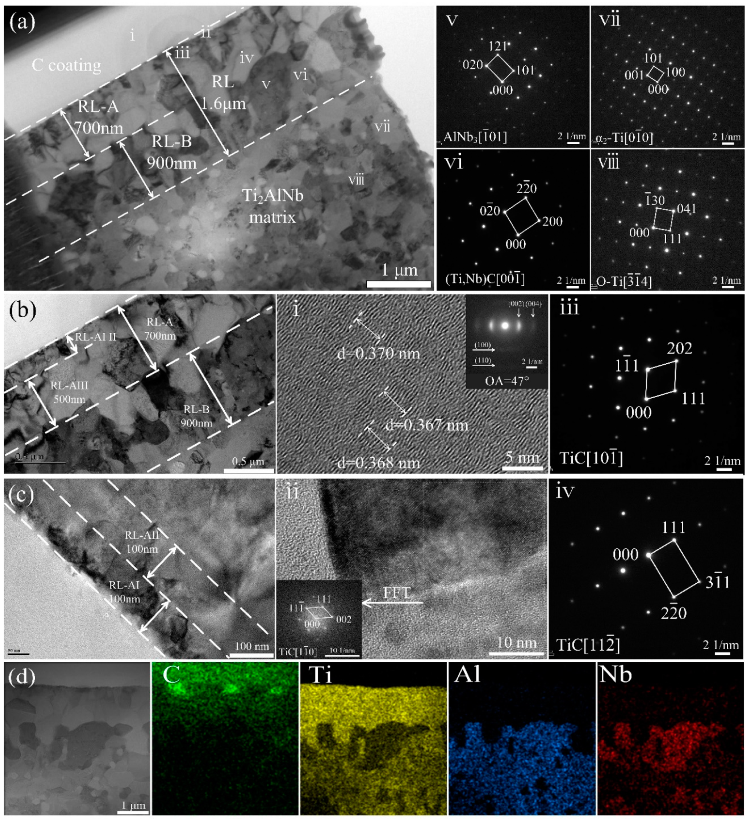
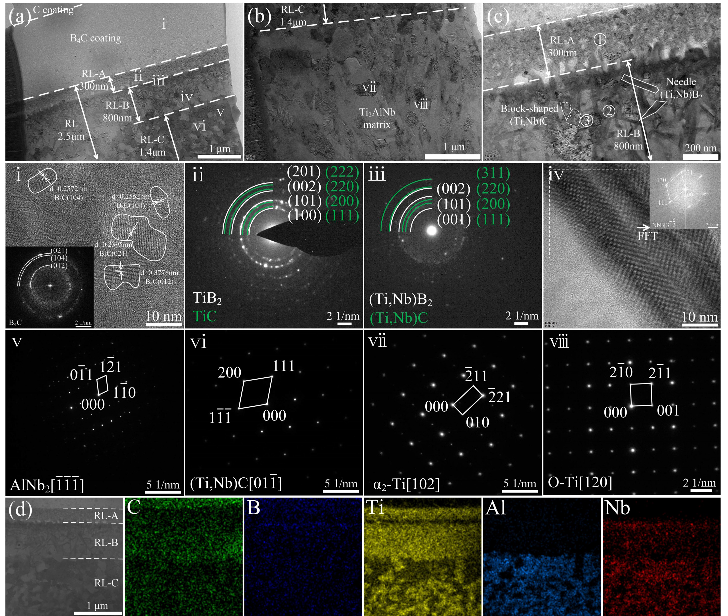
3.2. Interfacial Reactions in the SiCf/C/Ti2AlNb and SiCf/C/B4C/Ti2AlNb

Figure 4a,b show the cross-sectional overview of the SiCf/C/Ti2AlNb and SiCf/C/B4C/Ti2AlNb after consolidating at the same HIP condition. The fibers in both composites were uniformly arranged in a hexagonal distribution. Apparently, the interfacial reaction layers could be found between the residual barrier layer and the Ti2AlNb matrix in both composites, which might mainly come from the interdiffusion of elements between the adjacent layers during high-temperature HIP consolidation [2]. In the SiCf/C/Ti2AlNb, the RL was compact with no cracks or holes, and its thickness was evaluated to be ~1.6 μm. As C coating was utilized as the barrier layer of SiCf/Ti, the RL mainly arose from the continuous diffusion of C atoms from C coating into the adjacent Ti matrix and was essentially a TiC-based RL [16]. Near the RL, the Ti2AlNb matrix showed in a typical block or strip morphology. In the SiCf/C/B4C/Ti2AlNb, a thicker RL of ~2.5 μm in thickness formed between the B4C and Ti2AlNb matrix, as compared with that in the SiCf/C/Ti2AlNb. Compared to the SiCf/C/Ti2AlNb, the SiCf/C/B4C/Ti2AlNb allowed the boron atoms with a smaller size to easily diffuse in the gaps and the grain boundaries at a higher rate, consequently forming a thicker interfacial reaction layer. Clearly, besides the thickness of RL, the reaction products and their distribution in the RL can strongly impact on interfacial properties. In order to clarify the products distribution and the diffusion barriers-dominated interfacial reaction, the interfacial reaction zones were further observed by TEM
TEM bright field images of the interfacial reaction zones and the Ti2AlNb matrix in the SiCf/C/Ti2AlNb are shown in Figure 5. EDS analyses on concerned points are shown in Table 2. Based on the reaction products, the RL could be divided into two sub-layers, namely, RL-A near C coating and RL-B adjacent to the Ti2AlNb matrix. The RL-A was composed of TiCx, while the RL-B consisted of (Ti,Nb)C+AlNb3, as identified by the HRTEM and the SAED patterns in Figure 6ⅱ–ⅵ. Enlarged images of the RL-A are also displayed in Figure 5b,c. On basis of the size of TiCx grains, the RL-A could be further divided into RL-AI (fine-grained TiCx layer adjacent to C coating), RL-AII (transition layer of TiCx in the middle of RL-A zone), and RL-AIII (coarse-grained TiCx layer next to the RL-B). For SiCf/C/Ti2AlNb, the total thickness of RL-A was evaluated to be ~0.7 μm, consisting of ~100 nm RL-AI, ~100 nm RL-AII, and ~0.5 μm RL-AIII. Meanwhile, the grain size considerably increased from less than 100 nm for RL-AI to ~200 nm for RL-AII and ~500 nm for RL-AIII The gradual increase in TiCx grain size along RL-A could be explained by the fact that C atoms continuously diffuse from the C coating toward the matrix and the matrix grains grow at the same time during HIP. A description for the process of RL formation is available in our previous paper [28]. Unlike the RL-A that was only composed of TiCx, the RL-B mainly comprised (Ti,Nb)C and AlNb3, as confirmed by SAED and EDS in Figure 5ⅴ,vi. The scanning TEM (STEM) images and EDS mapping analyses of elements were obtained to further visualize the elemental distribution of the interfacial zones of the SiCf/C/Ti2AlNb, as shown in Figure 5d. The metallic elements in the matrix were almost completely blocked and located outside the C coating. By contrast, C atoms diffused from the C coating toward the matrix, which dominated the formation of interfacial reaction zones with C content gradient. Obviously, the reaction products in RL-A were all TiC. Based on the above observations, the sequence of reaction products in SiCf/C/Ti2AlNb was TiC and (Ti,Nb)C+AlNb3. This can be discussed as follows. Compared with the FFF foils commonly used by many researchers, the PVD Ti2AlNb was composed of lots of nanocrystalline grains, which could provide a large amount of channels for elemental diffusion. Accordingly, the interfacial reaction was supposed to be a reaction- and diffusion-controlled process. Table 3 lists the equations for describing the possible interfacial reactions occurring in the SiCf/C/Ti2AlNb composites and the corresponding ΔrG values [35,36]. Reaction 5 has a more negative value of ΔrG than reaction 10. In addition, Ti atoms have a higher diffusion rate than Nb atoms to the C coating during the reaction [37]. They resulted in the formation of TiC in the initial stage of the reaction. At the same time, the remaining high concentration of Al and Nb elements in the Ti-depletion matrix formed AlNb3. During the reaction, the elemental diffusion occurred simultaneously with the grain growth. When the near-stoichiometric TiC formed and thus became a C-diffusion barrier, the interfacial reaction that followed would transit from the reaction-controlled to the diffusion-controlled. Since the C source was absolutely sufficient, only a small amount of C passed through the RL-A and was located at its front end, and reacted with the Ti and Nb in the matrix to form (Ti,Nb)C. In this process, the formation of the relatively-stable AlNb3 phase and (Ti,Nb)C resulted in an Al-enriched zone, in which the reaction with C did not occur, thereby increasing the transition temperature of B2 phase in Ti2AlNb matrix. Near RL-B, the Ti2AlNb matrix mainly consisted of α2 and O phases, as identified by SAED.
TEM bright field images and EDS analyses of the interfacial reaction zones in the SiCf/C/B4C/Ti2AlNb are shown in Figure 6a,b and Table 4, respectively. The RLs (~2.5 μm in total thickness) could be divided into three sublayers based on the reaction products, namely RL-A, RL-B, and RL-C. Enlarged images of the RL-A and the RL-B are also displayed in Figure 6c. The RL-A, adjacent to the B4C coating, was composed of fine-grained TiB2 and TiC with the grain size of ~20 nm, as revealed by the SAED patterns in Figure 6ⅱ. This means that only Ti reacted with B and C in the RL-A. Across the RL-A, both Ti and Nb reacted with B and C, forming the RL-B. Thus, the RL-B consisted mainly of the block-shaped (Ti,Nb)C and the needle-shaped (Ti,Nb)B2 with the elongated grains, as indicated by SAED and EDS in Figure 6ⅲ,ⅳ and Table 2. Unlike the carbide products with equiaxed feature, the boride products existed in needle shape when their composition deviated from the stoichiometry [15]. In the RL-C outside the RL-B, only the C atom diffused across RL-B, whereas the B atom diffusion terminated in RL-B, forming the coarse-grained (Ti,Nb)C with the grain size of ~100 nm, together with AlNb2, as revealed by SAED and EDS in Figure 6ⅴ,ⅵ. Figure 6d shows the STEM images and EDS elemental maps of the interfacial zones in the SiCf/C/B4C/Ti2AlNb for further visualizing the elemental distribution. All reactions occurred outside the B4C coating, and the diffusion of B and C atoms dispersedly distributed throughout the reaction zone and dominated the reactants. The Ti, Nb, and Al elements started to appear in RL-A, RL-B, and RL-C in turn due to their different reactivity. Additionally, the clear boundaries of B4C coating and each sublayer of interfacial reaction zones can be distinguished in the SiCf/C/B4C/Ti2AlNb. The sequence of reaction products in the SiCf/C/B4C/Ti2AlNb was TiB2+TiC, (Ti,Nb)B2+(Ti,Nb)C+NbB, and (Ti,Nb)C+AlNb2, and will be discussed in detail as follows.
The initial stage of the interfacial reaction was a reaction-controlled process. The reactions (1), (2), (5), and (3), as listed in Table 3, took place preferentially because of the high diffusion rate of Ti and the high absolute values of ΔrG, and resulted in the production of TiB2 and TiC near the B-rich B4C coating in the RL-A. High concentration of B-rich B4C contributed to the production with high nucleation rate that hindered the grain growth of TiB2 and TiC, and lots of fine grains provided terrible crystalline-boundary diffusion paths for B and C atoms in the RL-A. As the reaction and the diffusion of the elements proceeded synchronously, Nb atoms began to participate during the reaction. A large amount of near-stoichiometric boride and (Ti,Nb)C (Ti-rich) in needle and block shape, respectively, were formed in the RL-B. These products in RL-B could be regarded as the diffusion barrier layer, which led to the interfacial reaction entering the diffusion-controlled dominated stage. After the formation of previous products, the remnant highly-concentrated elements of Nb and Al in the Ti-depletion matrix formed AlNb2 in the RL-C. Compared with the AlNb3 formation in the RL-B of SiCf/C/Ti2AlNb, the AlNb2 formation could be attributed to a certain amount of participated Nb atoms during the preformation of the borides. Simultaneously, a small amount of carbon released by the reactions diffused into the matrix and formed a bit of (Ti,Nb)C. Due to the equilibrium of reaction process, a large amount of Al atoms were not involved in the reactions, leading to the Al-enriched matrix. Consequently, the main constituent phases of this matrix adjacent to the RL-C were α2-Ti and O-Ti. The sequence of reaction products in the SiCf/C/B4C/Ti2AlNb is accordingly summarized in the schematic diagram, as shown in Figure 7.
In summary, the comprehensive SEM and TEM observations make it clear that in both the SiCf/C/Ti2AlNb and the SiCf/C/B4C/Ti2AlNb composites, the RL zones were formed via a two-stage process: the reaction-controlled and the diffusion-controlled. The according reaction products were identified as the different-sized TiC and the coarse-grained (Ti,Nb)C+AlNb3 for the SiCf/C/Ti2AlNb, and the fine-grained TiB2+TiC, the needle-shaped (Ti,Nb)B2/NbB+(Ti,Nb)C and the coarse-grained (Ti,Nb)C+AlNb2 for the SiCf/C/B4C/Ti2AlNb. Compared with the C single coating, owing to the B4C acting as the reaction front in the C/B4C duplex coating, the needle-shaped boride products facilitated elements diffusion and; thereby, formed a thicker RL.

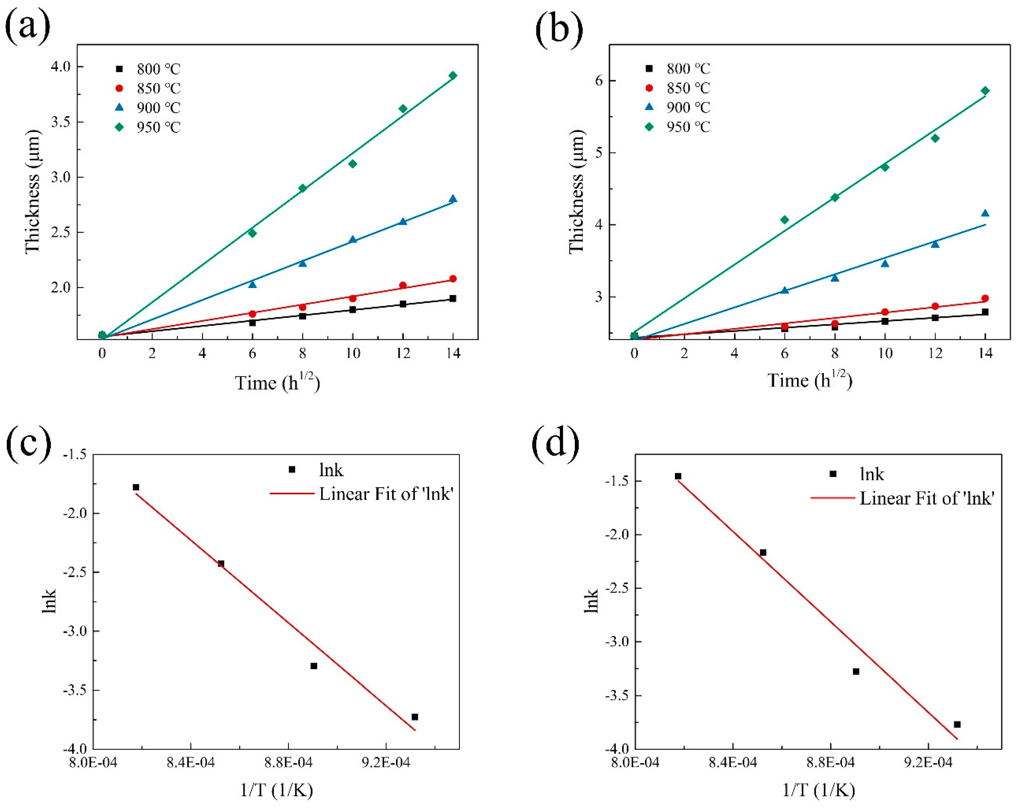
3.3. Reaction Kinetics of SiCf/C/Ti2AlNb and SiCf/C/B4C/Ti2AlNb

The interfacial reaction kinetics of SiCf/Ti is normally an indispensable and important basis for evaluating the thermal stability of SiCf/Ti and understanding the interfacial reaction mechanism of SiCf/Ti. The thickness of interfacial reaction zone develops progressively with the thermal exposure temperature and the increase of time. In detail, the thickness of RL is linearly related to the square of heat treatment time for the interfacial reaction zone in which the diffusion-controlled process dominates [38]. The total thickness of RL plotted as a function of the square root of reaction times at various heat treatment temperatures for the SiCf/C/Ti2AlNb and the SiCf/C/B4C/Ti2AlNb composites was estimated, respectively, and is shown in Figure 8a,b.
The reaction kinetics can be described by the following equations [39]:
x = kt1/2 + b0,
k = k0exp(−Q/2RT)
where x is the thickness of the RL, t is time, k is the reaction rate constant, b0 is the original thickness of the RL, R is the gas constant, Q is the activation energy, k0 is the frequency factor, and T is the temperature. The reaction rate k was determined from the slope of the curves for fitting the thickness of RL at different times. The logarithm of k vs. the reciprocal of T, according to Equation (2), was plotted and is shown in Figure 8c,d. The Q and k0 of the interfacial chemical reactions were subsequently calculated.
The activation energy Q and the rate constant k0 for the SiCf/C/Ti2AlNb and SiCf/C/B4C/Ti2AlNb composites were 292 kJ/mol, 0.457 cm/s1/2 and 350 kJ/mol, 11.4 cm/s1/2, respectively. Both the Q and the k0 can normally affect the growth of the RL in SiCf/Ti. The Q of SiCf/C/B4C/Ti2AlNb was larger than that of SiCf/C/Ti2AlNb, indicating that the former would be more difficult to react in the early reaction-controlled stage. However, since the pyrolytic C coating with stronger texture could hinder the outward diffusion of C atoms and the needle-shaped borides could facilitate the elemental diffusion, the k0 of SiCf/C/B4C/Ti2AlNb was much higher than that of SiCf/C/Ti2AlNb, which thereby resulted in a thicker RL of the former under the same consolidating conditions. Therefore, the growth rate of the RL in SiCf/Ti2AlNb is dependent on the interaction between the Q and the k0.

3.4. Interfacial Strength and Tensile Strength

The effect of RL thickness and reaction products on the SiCf/Ti composites were further explored by mechanical properties tests. It has been widely accepted that the interface strength of SiCf/Ti is a crucial parameter governing the failure modes of composites subjected to an external load, and thereby plays an important role in controlling the overall mechanical properties. Thus, push-out experiments were carried out to evaluate the interfacial properties of SiCf/C/Ti2AlNb and SiCf/C/B4C/Ti2AlNb composites. The load vs. displacement curve was determined and is shown in Figure 9. The interphase shear strength or interface strength, τd, at the load level, Pd, corresponding to the initial debonding, can be calculated based on the following formula [40]:
τd = Pd/πdfh
where df is the diameter of SiC fiber and h is the thickness of composite. The average values of Pd for SiCf/C/Ti2AlNb and SiCf/C/B4C/Ti2AlNb were measured to be ~7.9 and ~5.6 N, respectively. By substituting Pd, the calculated values of τd were ~72 MPa for SiCf/C/Ti2AlNb and ~51 MPa for SiCf/C/B4C/Ti2AlNb. Fibers push-out were verified through SEM observations of the front and the reverse side of each specimen, as shown in Figure 10. The interfacial debonding took place at the location between the C coating and the RL for the SiCf/C/Ti2AlNb, and at the location between the C coating and the B4C coating for the SiCf/C/B4C/Ti2AlNb. It is generally believed that, within a certain thickness range, the τd of the composites can be determined by the thickness of interfacial zone including diffusion barriers and RL. An elevated thickness of the interfacial zone appropriately would result in a higher value of τd for SiCf/C/Ti2AlNb [16,27,28]. However, the interfacial debonding that occurred between pyrolytic carbon and amorphous polycrystalline structure of B4C resulted in a poor interfacial bond strength. Therefore, the τd for SiCf/C/B4C/Ti2AlNb was lower than that for SiCf/C/Ti2AlNb, even though the former had a thicker interfacial zone.
We further carried out the room temperature tensile tests of the SiCf/C/Ti2AlNb and the SiCf/C/B4C/Ti2AlNb composites, with the tensile curves of SiCf/C/Ti2AlNb and SiCf/C/B4C/Ti2AlNb shown in Figure 11. The average tensile strength values of SiCf/C/Ti2AlNb and SiCf/C/B4C/Ti2AlNb were calculated to be ~1360 and ~1150 MPa, respectively. The tensile strength of SiCf/C/Ti2AlNb is ~200 MPa higher than that of SiCf/C/B4C/Ti2AlNb. This could be attributed to the difference in interfacial zone, although they had the same fibers and matrix alloy. Figure 12 shows the tensile fracture morphologies of SiCf/C/Ti2AlNb and SiCf/C/B4C/Ti2AlNb. Both two composites displayed an identical step-like fracture mode. This fracture behavior involved only the obvious push-out of short fibers; not the brush-like fracture caused by a too-low τd nor the brittle facture induced by a too-high τd due to lower interfacial debonding. However, in contrast to the fractograph of SiCf/C/B4C/Ti2AlNb, the fractograph of SiCf/C/Ti2AlNb exhibited more serious steps between the near regions of fiber and the surrounding matrix, corresponding to more obvious crack deflections. The difference in fracture characteristics are determined by the τd. Compared with the SiCf/C/B4C/Ti2AlNb, more cracks usually initiated at the interfacial layers of the SiCf/C/Ti2AlNb, that has a higher τd and better interface/matrix matching, as the process of continuous loading increased. When the crack passing through the brittle Ti2AlNb matrix propagated to the next interfacial layer, the crack easily changed the propagation direction and continued to extend along the plane of other cracks. This fracture behavior means that the crack would travel through a longer path and consume more fracture energy. Probably for this reason, the SiCf/C/Ti2AlNb had a higher tensile strength than the SiCf/C/B4C/Ti2AlNb, with more fiber bridges in the fracture morphology of SiCf/C/Ti2AlNb, as shown in Figure 12a. In a word, as the interfacial debonding totally dominated the tensile failure, the higher τd would aid in improving the tensile strength.

4. Conclusions

Both C coating and C/B4C duplex coating were successfully fabricated onto SiC fibers by CVD and then consolidated into SiCf/C/Ti2AlNb and SiCf/C/B4C/Ti2AlNb after HIP. On the basis of microstructure observations and mechanical properties tests of two composites, we make the following conclusions:
(1)
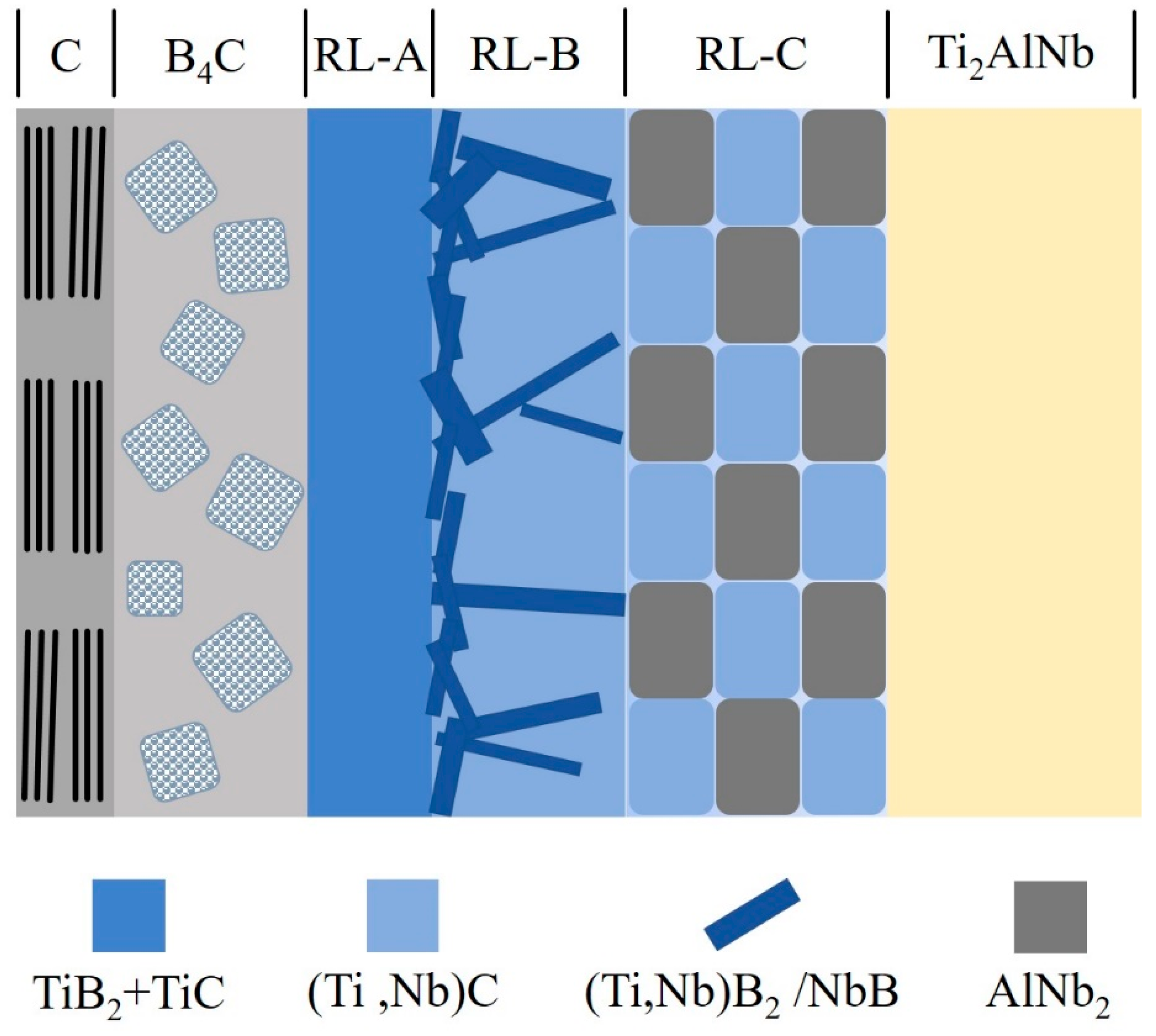
C-coated and C/B4C duplex-coated SiC fiber-reinforced Ti2AlNb composites were fabricated and the interfacial reaction products of both composites were identified. The reaction products sequence was the different-sized TiC and the coarse-grained (Ti,Nb)C+AlNb3 for the SiCf/C/Ti2AlNb; and the fine-grained TiB2+TiC, needle-shaped (Ti,Nb)B2/NbB +(Ti,Nb)C, and coarse-grained (Ti,Nb)C+AlNb2 for the SiCf/C/B4C/Ti2AlNb. When the interfacial reaction process of two composites was dominated by the diffusion-controlled, the SiCf/C/B4C/Ti2AlNb had a higher diffusion activation energy Q due to the facilitated elemental diffusion by the needle-shaped borides, making the frequency factor k0 much larger than SiCf/C/Ti2AlNb, which resulted in a thicker RL in SiCf/C/B4C/Ti2AlNb under the same consolidating conditions.
(2)
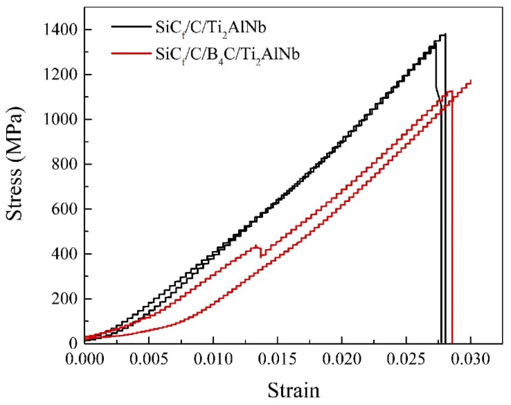
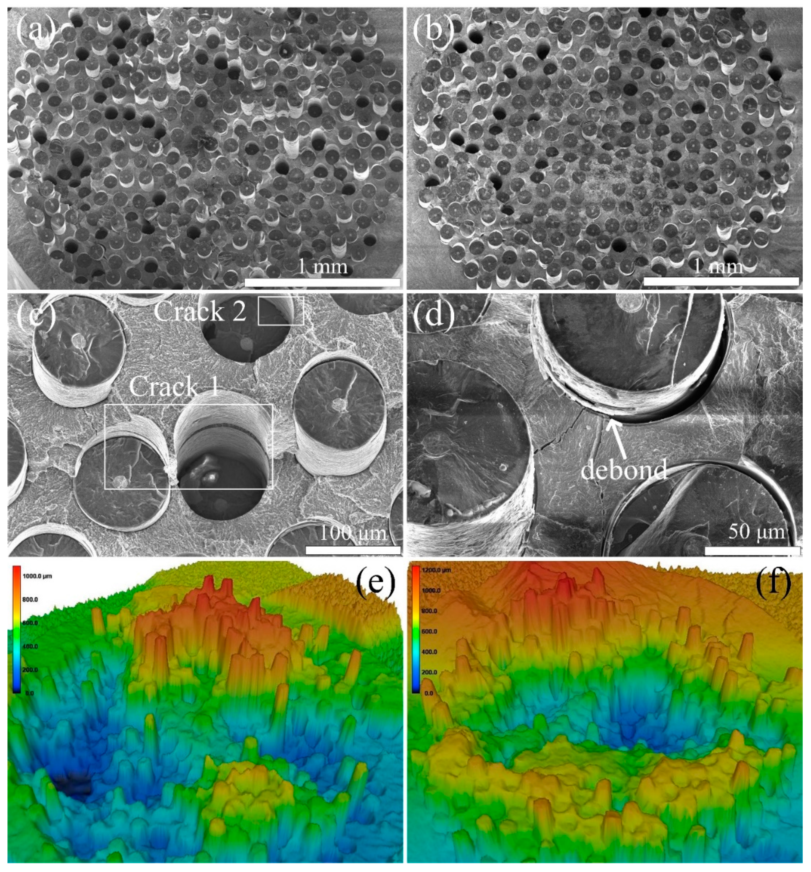
The SiCf/C/Ti2AlNb with a thinner RL exhibited a higher interface strength than SiCf/C/B4C/Ti2AlNb when the interfacial debonding occurred between pyrolytic carbon and the amorphous polycrystalline structure of B4C. The SiCf/C/Ti2AlNb with a higher interface strength exhibited a more serious step-like fracture than SiCf/C/B4C/Ti2AlNb and thus contributed to a higher tensile strength of the SiCf/C/Ti2AlNb.

Author Contributions

Conceptualization, Q.W. and H.H.; data curation, S.Z.; formal analysis, S.Z. and H.L.; funding acquisition, Q.W. and M.W. (Mao Wen); investigation, S.Z.; methodology, S.Z.; project administration, Q.W.; resources, H.H.; supervision, H.H.; validation, S.Z., J.C. and W.F.; visualization, C.X.; writing—original draft, S.Z.; writing—review and editing, M.W. (Minjuan Wang) and M.W (Mao Wen).

Funding

This research was funded by the National Key Research and Development Program of China (grant number 2016YFB0301203) and the National Natural Science Foundation of China (grant number 51871109).

Acknowledgments

This work were supported by the National Key Research and Development Program of China (grant number 2016YFB0301203) and the National Natural Science Foundation of China (grant number 51871109).

Conflicts of Interest

The authors declare no conflicts of interest. The funders had no role in the design of the study; in the collection, analyses, or interpretation of data; in the writing of the manuscript, or in the decision to publish the results.

References

  1. Larsen, J.M.; Russ, S.M.; Jones, J.W. An evaluation of fiber-reinforced titanium matrix composites for advanced high-temperature aerospace applications. Met. Mater. Trans. A 1995, 26, 3211–3223. [Google Scholar] [CrossRef]
  2. Guo, Z.X.; Derby, B. Solid-state fabrication and interfaces of fiber reinforced metal matrix composites. Prog. Mater. Sci. 1995, 39, 411–495. [Google Scholar] [CrossRef]
  3. Leyens, C.; Kocian, F.; Hausmann, J.; Kaysser, W.A. Materials and design concepts for high performance compressor components. Aerosp. Sci. Technol. 2003, 7, 201–210. [Google Scholar] [CrossRef]
  4. Singerman, S.; Jackson, J. Titanium Metal Matrix Composites for Aerospace Applications. Superalloys 1996, 579–586. [Google Scholar]
  5. Mall, S. Titanium Matrix Composites: Mechanical Behavior; CRC Press: Lancaster, PA, USA, 1997. [Google Scholar]
  6. Breuer, J.; Wilger, T.; Friesel, M.; Herzig, C. Interstitial and substitutional diffusion of metallic solutes in Ti3Al. Intermetallics 1999, 7, 381–388. [Google Scholar] [CrossRef]
  7. Lütjering, G.; Williams, J.C. Titanium, 2nd ed.; Springer Science & Business Media: Berlin, Germany, 2007. [Google Scholar]
  8. Banerjee, D.; Gogia, A.K.; Nandi, T.K.; Joshi, V.A. A new ordered orthorhombic phase in a Ti3AlNb alloy. Acta Metall. 1988, 36, 871–882. [Google Scholar] [CrossRef]
  9. Banerjee, D. The intermetallic Ti2AlNb. Prog. Mater. Sci. 1997, 42, 135–158. [Google Scholar] [CrossRef]
  10. Kumpfert, J. Intermetallic Alloys Based on Orthorhombic Titanium Aluminide. Adv. Eng. Mater. 2001, 3, 851. [Google Scholar] [CrossRef]
  11. Ward-Close, C.; Minor, R.; Doorbar, P. Intermetallic-matrix composites—A review. Intermetallics 1996, 4, 217–229. [Google Scholar] [CrossRef]
  12. Brunet, A.; Valle, R.; Vassel, A. Intermetallic TiAl-based matrix composites: Investigation of the chemical and mechanical compatibility of a protective coating adapted to an alumina fiber. Acta Mater. 2000, 48, 4763–4774. [Google Scholar] [CrossRef]
  13. Smith, P.R.; Graves, J.A.; Rhodes, C. Comparison of orthorhombic and alpha-two titanium aluminides as matrices for continuous SiC-reinforced composites. Met. Mater. Trans. A 1994, 25, 1267–1283. [Google Scholar] [CrossRef]
  14. Luo, X.; Wang, Y.Q.; Yang, Y.Q.; Zhang, M.X.; Huang, B.; Liu, S.; Jin, N. Effect of C/Mo duplex coating on the interface and tensile strength of SiCf/Ti-21Al-29Nb composites. J. Alloys Compd. 2017, 721, 653–660. [Google Scholar] [CrossRef]
  15. Yang, Y.; Zhu, Y.; Ma, Z.; Chen, Y.; Yang, Y. Formation of interfacial reaction products in SCS-6 SiC/Ti2AlNb composites. Scr. Mater. 2004, 51, 385–389. [Google Scholar] [CrossRef]
  16. Wu, M.; Zhang, K.; Huang, H.; Wang, M.; Li, H.; Zhang, S.; Wen, M. Interfacial reactions in SiCf/C/Ti17 composites dominated by texture of carbon coatings. Carbon 2017, 124, 238–249. [Google Scholar] [CrossRef]
  17. Dudek, H.J.; Borath, R.; Leucht, R.; Kaysser, W.A. Transmission electron microscopy of the fiber-matrix interface in SiC-SCS-6-fiber-reinforced IMI834 alloys. J. Mater. Sci. 1997, 32, 5355–5362. [Google Scholar] [CrossRef]
  18. Gentile, M.; Xiao, P.; Abram, T. Palladium interaction with silicon carbide. J. Nucl. Mater. 2015, 462, 100–107. [Google Scholar] [CrossRef]
  19. Kieschke, R.; Clyne, T. Development of a diffusion barrier for SiC monofilaments in titanium. Mater. Sci. Eng. A 1991, 135, 145–149. [Google Scholar] [CrossRef]
  20. Choy, K.L. Functionally graded coatings on SiC fibers for protection in Ti-based metal matrix composites. Scr. Mater. 1996, 34, 1753–1758. [Google Scholar] [CrossRef]
  21. Choy, K.L.; Durodola, J.F.; Derby, B.; Ruiz, C. Effect of TiB2, TiC and TiN protective coatings on tensile strength and fracture behaviour of SiC monofilament fibers. Composites 1995, 26, 531–539. [Google Scholar] [CrossRef]
  22. Luo, X.; Yang, Y.; Sun, Q.; Yu, Y.; Huang, B.; Chen, Y. Effect of Cu/Mo duplex coating on the interface and property of SiCf/Ti6Al4V composite. Mater. Sci. Eng. A 2012, 535, 6–11. [Google Scholar] [CrossRef]
  23. XRD and TG-DSC Analysis of the Silicon Carbide-Palladium Reaction. Available online: https://www.researchgate.net/publication/265595117_XRD_and_TG-DSC_Analysis_of_the_Silicon_Carbide-Palladium_Reaction (accessed on 25 September 2019).
  24. Fu, Y.; Shi, N.; Zhang, D.; Yang, R. Effect of C coating on the interfacial microstructure and properties of SiC fiber-reinforced Ti matrix composites. Mater. Sci. Eng. A 2006, 426, 278–282. [Google Scholar] [CrossRef]
  25. Huang, B.; Yang, Y.; Luo, H.; Yuan, M. Effects of the coating system and interfacial region thickness on the thermal residual stresses in SiCf/Ti–6Al–4V composites. Mater. Des. 2009, 30, 718–722. [Google Scholar] [CrossRef]
  26. Zhang, W.; Yang, Y.; Zhao, G.; Feng, Z.; Huang, B.; Luo, X.; Li, M.; Chen, Y.; Yang, Y. Interfacial reaction studies of B4C-coated and C-coated SiC fiber reinforced Ti–43Al–9V composites. Intermetallics 2014, 50, 14–19. [Google Scholar] [CrossRef]
  27. Wang, M.-J.; Huang, H.; Li, H.; Zhang, S.-M.; Wen, M.; Song, C.; Pan, F. Microstructure and interfacial strength of SiC fiber-reinforced Ti17 alloy composites with different consolidation temperatures. Rare Met. 2018, 37, 759–768. [Google Scholar] [CrossRef]
  28. Zhang, S.; Wang, M.; Wen, M.; Wu, M.; Wang, Q.; Huang, H. Interfacial reactions and matrix microstructure evolution in SiCf/Ti composites dominated by primary structure of Ti matrix. Ceram. Int. 2019, 45, 17767–17774. [Google Scholar] [CrossRef]
  29. Sun, Q.; Luo, X.; Yang, Y.; Feng, G.; Zhao, G.; Huang, B.; Yang, Y. A review on the research progress of push-out method in testing interfacial properties of SiC fiber-reinforced titanium matrix composites. Compos. Interfaces 2015, 22, 367–386. [Google Scholar] [CrossRef]
  30. Díaz, J.; Paolicelli, G.; Ferrer, S.; Comin, F. Separation of the sp3 and sp2 components in the C1 s photoemission spectra of amorphous carbon films. Phys. Rev. B 1996, 54, 8064–8069. [Google Scholar] [CrossRef]
  31. Mc Evoy, N.; Peltekis, N.; Kumar, S.; Rezvani, E.; Nolan, H.; Keeley, G.P.; Blau, W.J.; Duesberg, G.S. Synthesis and analysis of thin conducting pyrolytic carbon films. Carbon 2012, 50, 1216–1226. [Google Scholar] [CrossRef]
  32. Cao, X.; Shang, L.; Liang, Y.; Lu, Z.; Zhang, G.; Xue, Q. The effect of tribo-chemical reactions of mating materials on tribological behaviors of the B4C film in various relative humidity environments. Ceram. Int. 2019, 45, 4581–4589. [Google Scholar] [CrossRef]
  33. Bourrat, X.; Trouvat, B.; Limousin, G.; Vignoles, G.; Doux, F. Pyrocarbon anisotropy as measured by electron diffraction and polarized light. J. Mater. Res. 2000, 15, 92–101. [Google Scholar] [CrossRef]
  34. Reznik, B.; Hüttinger, K. On the terminology for pyrolytic carbon. Carbon 2002, 40, 621–624. [Google Scholar] [CrossRef]
  35. Langeʼs Handbook of Chemistry. Available online: https://www.researchgate.net/publication/249343603_Langes_Handbook_of_Chemistry (accessed on 17 September 2019).
  36. Lihrmann, J.-M. Thermodynamics of the Al2O3–Al4C3 system: I. Thermochemical functions of Al oxide, carbide and oxycarbides between 298 and 2100K. J. Eur. Ceram. Soc. 2008, 28, 633–642. [Google Scholar] [CrossRef]
  37. Hansen, M.; Kamen, E.L.; Kessler, H.D.; McPherson, D.J. Systems Titanium-Molybdenum and Titanium-Columbium. JOM 1951, 3, 881–888. [Google Scholar] [CrossRef]
  38. Yang, Y.; Dudek, H.; Kumpfert, J.; Yang, Y. Interfacial reaction and stability of SCS-6 SiC/Ti–25Al–10Nb–3V–1Mo composites. Mater. Sci. Eng. A 1998, 246, 213–220. [Google Scholar] [CrossRef]
  39. Yang, Y.Q.; Dudek, H.J.; Kumpfert, J. TEM investigations of the fiber/matrix interface in SCS-6 SiC/Ti–25Al–10Nb–3V–1Mo composites. Compos. Part A: Appl. Sci. Manuf. 1998, 29, 1235–1241. [Google Scholar] [CrossRef]
  40. Mei, H.; Bai, Q.; Sun, Y.; Li, H.; Wang, H.; Cheng, L. The effect of heat treatment on the strength and toughness of carbon fiber/silicon carbide composites with different pyrolytic carbon interphase thicknesses. Carbon 2013, 57, 288–297. [Google Scholar] [CrossRef]
Figure 1. Specific strength (a) and modulus (b) of several unidirectional TMCs and a nickel-based superalloy.
Materials 12 03257 g001
Figure 2. Tensile specimens of SiCf/Ti2AlNb.
Materials 12 03257 g002
Figure 3. Cross-sectional SEM micrographs of SiCf/Ti2AlNb precursor wires for (a) SiCf/C/Ti2AlNb and (b) SiCf/C/B4C/Ti2AlNb; and typical XPS patterns for (c) C coating and (d) B4C coating.
Materials 12 03257 g003
Figure 4. Microstructure of SiCf/Ti2AlNb observed by SEM for (a,c) SiCf/C/Ti2AlNb and (b,d) SiCf/C/B4C/Ti2AlNb.
Materials 12 03257 g004
Figure 5. (a–c) TEM bright field images and high magnification images of interfacial reaction products for SiCf/C/Ti2AlNb; (d) STEM image and EDS mappings of the interfacial zones for SiCf/C/Ti2AlNb; (iviii) shows the HRTEM images of C coating and SAED patterns of interfacial reaction products for SiCf/C/Ti2AlNb marked in (a).
Materials 12 03257 g005
Figure 6. (a–c) TEM bright field images and high magnification images of interfacial reaction products for SiCf/C/B4C/Ti2AlNb; (d) STEM image and EDS mappings of the interfacial zones for SiCf/C/B4C/Ti2AlNb; (iviii) shows the HRTEM images of B4C coating and SAED patterns of interfacial reaction products for SiCf/C/B4C/Ti2AlNb marked in (a) and (b).
Materials 12 03257 g006
Figure 7. Schematic of interfacial reaction products in SiCf/C/B4C/Ti2AlNb composite.
Materials 12 03257 g007
Figure 8. The total thickness of the reaction zone at various temperatures as a function of the square root of time for (a) SiCf/C/Ti2AlNb and (b) SiCf/C/B4C/Ti2AlNb composites; the logarithm of the reaction rates vs. reciprocal of the heat treatment temperature for (c) SiCf/C/Ti2AlNb and (d) SiCf/C/B4C/Ti2AlNb composites.
Materials 12 03257 g008
Figure 9. Typical fiber push-out load–displacement curves for SiCf/C/Ti2AlNb and SiCf/C/B4C/Ti2AlNb.
Materials 12 03257 g009
Figure 10. Appearance of the push-out fibers at the top and bottom of the test specimen for (a,b) SiCf/C/Ti2AlNb and (c,d) SiCf/C/B4C/Ti2AlNb.
Materials 12 03257 g010
Figure 11. Typical tensile stress–strain curves of SiCf/C/Ti2AlNb and SiCf/C/B4C/Ti2AlNb.
Materials 12 03257 g011
Figure 12. Low-magnification fractographs of (a) SiCf/C/Ti2AlNb and (b) SiCf/C/B4C/Ti2AlNb; high-magnification fractographs of (c) SiCf/C/Ti2AlNb and (d) SiCf/C/B4C/Ti2AlNb; fracture morphologies of (e) SiCf/C/Ti2AlNb and (f) SiCf/C/B4C/Ti2AlNb observed by LSCM.
Materials 12 03257 g012
Table 1. Comparative properties of Titanium metal matrix composites (Ti MMCs) and superalloys.
Properties (Direction of Fibers)Conventional Ti MMCTi Aluminide Ti MMCSuperalloys
Density, g/cm34.044.188.3
Stiffness, GPa200242207
Max use temperature, ℃5387601090
CTE, °C1 × 10-68.919.1813.0
Table 2. Chemical composition of interfacial reaction products in SiCf/C/Ti2AlNb composite (at.%).
PositionCTiAlNb
a (ⅱ)80.1519.85--
a (ⅳ)76.5423.46--
a (ⅴ)17.2316.2918.6347.85
a (ⅵ)59.7533.850.406.00
Table 3. Equations of the interfacial reactions occurred in SiCf/C/Ti2AlNb and SiCf/C/B4C/Ti2AlNb composites and the corresponding ΔrG values at 970 °C.
No.Interfacial Reaction EquationΔrG/kJ mol−1
12Ti + B4C = 2TiB2 + C−230.5
2Ti + 2B = TiB2−258.7
3Ti + B = TiB−155.6
4Ti + B4C = TiC + 4B−111.9
5Ti + C = TiC−170.3
6TiB2 + Ti = 2TiB−52.4
72Nb + B4C = 2NbB2 + C−133.7
8Nb + 2B = NbB2−162.9
9Nb + B = NbB−107.7
10Nb + C = NbC−134
114Al + 3C = Al4C3−138
Table 4. Chemical composition of interfacial reaction products in SiCf/C/B4C/Ti2AlNb composite (at.%).
PositionBCTiAlNb
Spot 1 (RL-A)65.1414.1020.76--
Spot 2 (fine needle in RL-B)62.259.5013.880.2314.13
Spot 3 (block in RL-B)40.2128.2727.380.233.91
RL—reaction layer, The RLs could be divided into three sublayers based on the reaction products, namely RL-A, RL-B, and RL-C.

