Study on Hardness, Microstructure, Distribution of the Self-lubricating Phase, Friction and Wear Property of 1Cr13MoS after Heat Treatment


Abstract
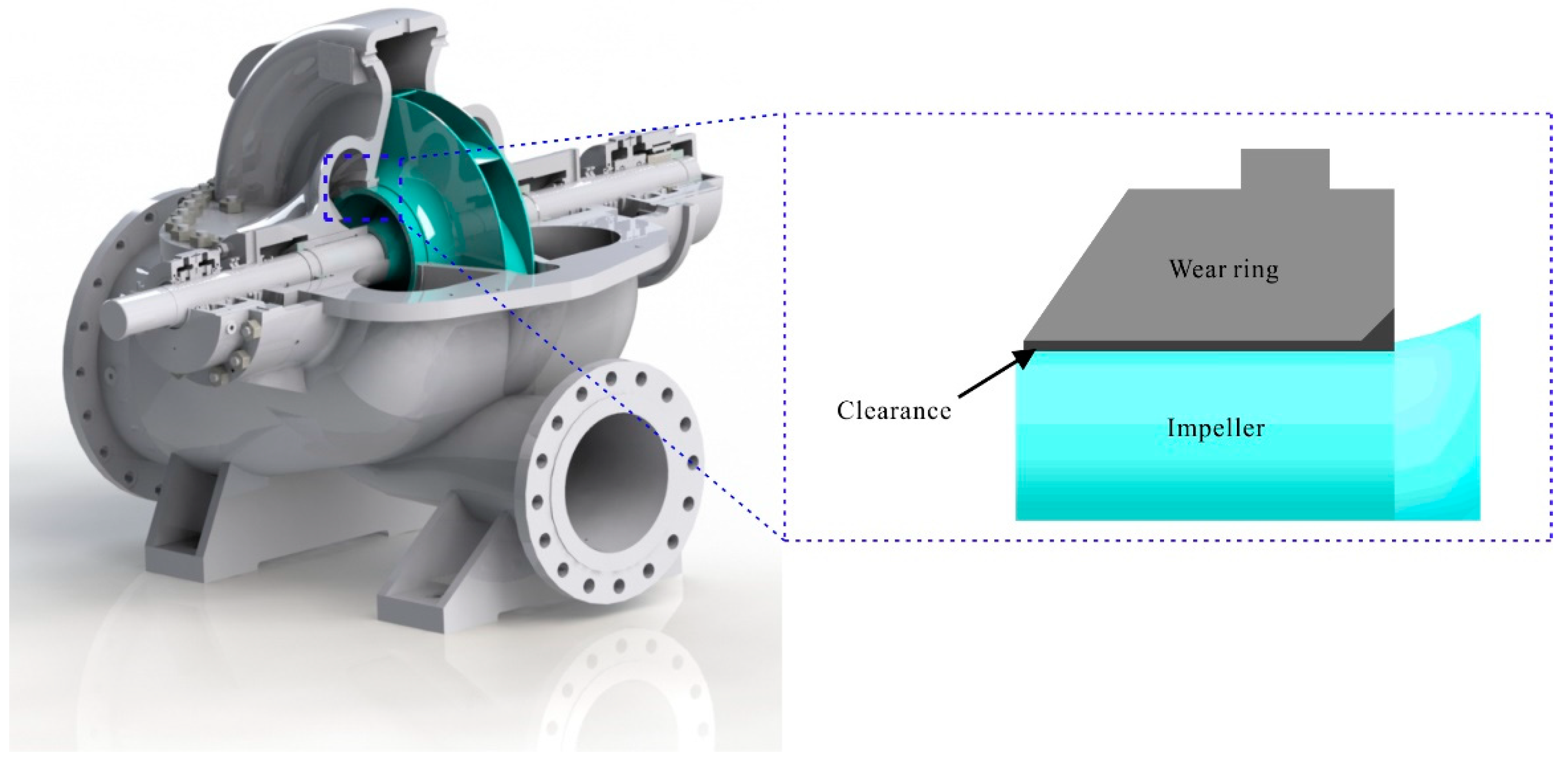
:1. Introduction
2. Material and Method
2.1. Material Preparation
2.2. Characterization of 1Cr13MoS
2.2.1. Hardness and Microstructure Analysis
2.2.2. Analysis of Self-Lubricating Phase and Impurity Phase
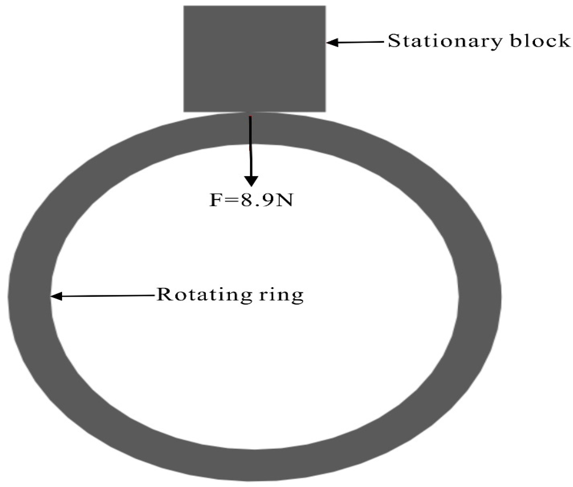
2.2.3. Friction and Wear Performance
3. Results and Discussion
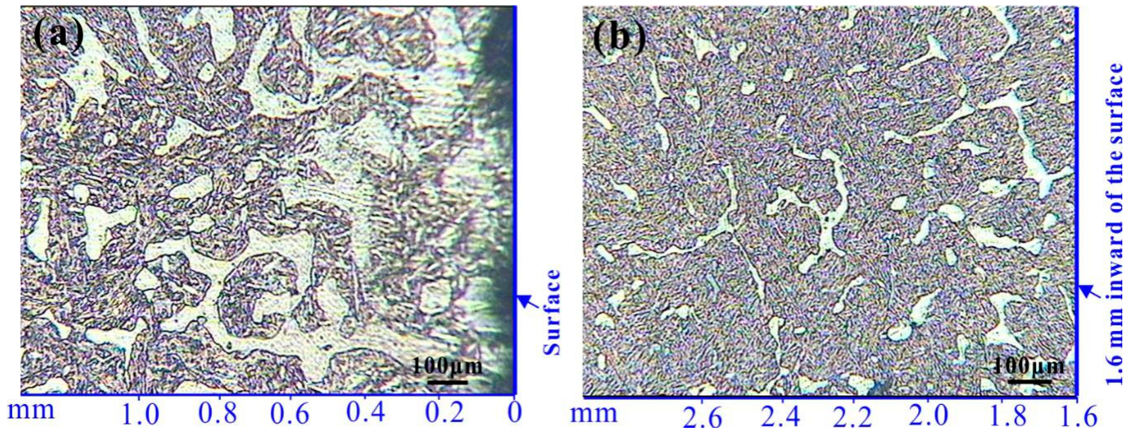
3.1. Hardness and Microstructure
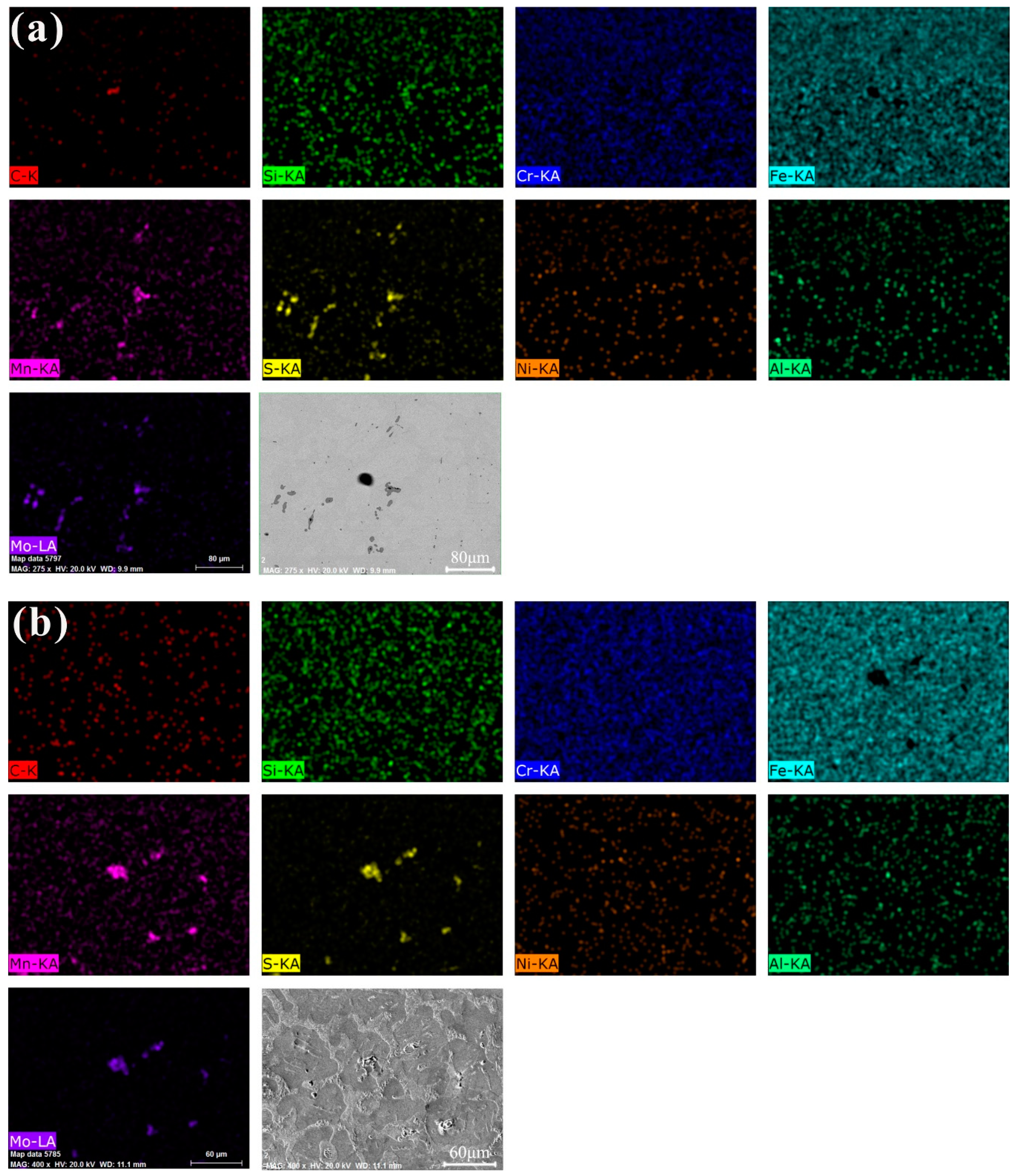
3.2. Analysis of Self-Lubricating Phase and Impurity Phase
3.2.1. Distribution of Self-Lubricating Phase
3.2.2. Morphology and Size of These Heterogeneous Phases
3.3. Friction and Wear Performance
4. Conclusions
Author Contributions
Funding
Conflicts of Interest
References
- Karassik, I.J.; Messina, J.P.; Cooper, P.; Heald, C.C. Pump Handbook; McGraw-Hill: New York, NY, USA, 2003. [Google Scholar]
- API 610, Centrifugal Pumps for Petroleum, Petrochemical and Natural Gas Industries; ANSI/API: Washington, WA, USA, 2010.
- Yin, Y.G.; Lin, F.D.; Yao, W.; Xie, T.; Yu, J.W. Tribological properties of the surface bonded self-lubricating coating. Adv. Mater. Res. 2010, 154, 583–587. [Google Scholar] [CrossRef]
- Yang, K.; Shi, X.; Huang, Y.; Wang, Z.; Wang, Y.; Zhang, A.; Zhang, Q. The research on the sliding friction and wear behaviors of TiAl-10wt% Ag at elevated temperatures. Mater. Chem. Phys. 2017, 186, 317–326. [Google Scholar] [CrossRef]
- Miyoshi, K. Solid Lubrication Fundamentals and Applications; Marcel Dekker Inc: New York, NY, USA, 2001. [Google Scholar]
- Evans, D.C.; Senior, G.S. Self-lubricating materials for plain-bearings. Tribol. Int. 1982, 15, 243–248. [Google Scholar] [CrossRef]
- Kostornov, A.G.; Fushchich, O.I. Sintered antifriction materials. Powder. Metall. Met. Ceram. 2007, 46, 503–512. [Google Scholar] [CrossRef]
- Sustarsic, B.; Kosec, L.; Jenko, M.; Leskovsek, V. Vacuum sintering of water-atomised HSS powders with MoS2 additions. Vacuum 2001, 61, 471–477. [Google Scholar] [CrossRef]
- Slys’, I.G.; Perepelkin, A.V.; Fedorchenko, I.M. Structure and properties of sintered stainless steel containing molybdenum disulfide. Powder. Metall. Met. Ceram. 1973, 12, 710–714. [Google Scholar] [CrossRef]
- Davis, J.R. Asm Specialty Handbook: Copper and Copper Alloys; Asm International: Ohio, OH, USA, 2001. [Google Scholar]
- Lancaster, J.K. Transfer lubrication for high temperatures: A review. J. Tribol. 1985, 107, 437–443. [Google Scholar] [CrossRef]
- Tsuya, Y.; Umeda, K.; Kitamura, M. Optimum concentration of solid lubricant in compact. Lubr. Eng. 1976, 32, 402–407. [Google Scholar]
- EN 10088-3, Part 3. Technical Delivery Conditions for Semi-Finished Products, Bars, Rods and Sections for General Purposes; BSI Standards Publication: London, UK, 2014.
- Holappa, L.E.K.; Helle, A.S. Inclusion control in high-performance steels. J. Mater. Process. Technol. 1995, 53, 177–186. [Google Scholar] [CrossRef]
- Steninger, J.; Melander, A. The relation between bendability, tensile properties and particle structure of low carbon steel, Scand. J. Metall. 1982, 11, 55–71. [Google Scholar]
- Pickering, F.B. Physical Metallurgy and the Design of Steels; Applied Science Publishers Ltd.: London, UK, 1978. [Google Scholar]
- Zeng, Y.P.; Fan, H.M.; Xie, X.S. Effects of the shape and size of rectangular inclusions on the fatigue cracking behavior of ultra-high strength steels. Int. J. Miner. Metall. Mater. 2013, 20, 360–364. [Google Scholar] [CrossRef]
- Gladman, T. The Physical Metallurgy of Microalloyed Steels; Maney Publishing: Leeds, UK, 2002. [Google Scholar]
- Pelleg, J. Mechanical Properties of Materials; Springer Netherlands: Berlin, Germany, 2013. [Google Scholar]
- Johnson, K.L. Contact Mechanics; Cambridge University Press: Cambridge, UK, 1985. [Google Scholar]


| Element | C | Mn | Si | S | P | Cr | Ni | Mo | Fe |
|---|---|---|---|---|---|---|---|---|---|
| Control range | 0.12~0.15 | 0.2~0.6 | 0.3~0.8 | 0.25~0.32 | ≤0.025 | 12~14 | ≤0.35 | 0.3~0.6 | balance |
| Measured value | 0.149 | 0.414 | 0.68 | 0.32 | 0.02 | 13 | 0.16 | 0.37 | balance |
| Friction Pairs | Mass Loss (g) | Friction Coefficient | |
|---|---|---|---|
| Block | Ring | Block | |
| X20Cr13 | X12Cr13 | 0.2954 | 0.8401 |
| 1Cr13MoS | X12Cr13 | 0.1665 | 0.5246 |
© 2019 by the authors. Licensee MDPI, Basel, Switzerland. This article is an open access article distributed under the terms and conditions of the Creative Commons Attribution (CC BY) license (http://creativecommons.org/licenses/by/4.0/).
Share and Cite
Li, S.; Che, Y.; Song, J.; Li, C.; Shu, Y.; He, J.; Yang, B. Study on Hardness, Microstructure, Distribution of the Self-lubricating Phase, Friction and Wear Property of 1Cr13MoS after Heat Treatment. Materials 2019, 12, 3171. https://doi.org/10.3390/ma12193171
Li S, Che Y, Song J, Li C, Shu Y, He J, Yang B. Study on Hardness, Microstructure, Distribution of the Self-lubricating Phase, Friction and Wear Property of 1Cr13MoS after Heat Treatment. Materials. 2019; 12(19):3171. https://doi.org/10.3390/ma12193171
Chicago/Turabian StyleLi, Shaolong, Yusi Che, Jianxun Song, Chenyao Li, Yongchun Shu, Jilin He, and Bin Yang. 2019. "Study on Hardness, Microstructure, Distribution of the Self-lubricating Phase, Friction and Wear Property of 1Cr13MoS after Heat Treatment" Materials 12, no. 19: 3171. https://doi.org/10.3390/ma12193171
APA StyleLi, S., Che, Y., Song, J., Li, C., Shu, Y., He, J., & Yang, B. (2019). Study on Hardness, Microstructure, Distribution of the Self-lubricating Phase, Friction and Wear Property of 1Cr13MoS after Heat Treatment. Materials, 12(19), 3171. https://doi.org/10.3390/ma12193171