Article

A New Mechanism of Dynamic Phase Transformations in An Isothermal Forged Beta–Gamma Intermetallic Alloy

1
School of Materials Science and Engineering, Tongji University, Shanghai 201804, China
2
School of Materials Science and Engineering, Harbin Institute of Technology, Weihai 264209, China
3
College of Mechatronics and Control Engineering, Shenzhen University, Shenzhen 518060, China
4
Department of Mechanical and Industrial Engineering, Ryerson University, Toronto, ON M5B 2K3, Canada
*
Authors to whom correspondence should be addressed.
Materials 2019, 12(17), 2787; https://doi.org/10.3390/ma12172787
Submission received: 27 July 2019 / Revised: 22 August 2019 / Accepted: 27 August 2019 / Published: 30 August 2019
(This article belongs to the Section Advanced Materials Characterization)

Abstract

:
A new mechanism of dynamic phase transformations of α2 ↔ γ in an isothermally forged γ-TiAl-based alloy that occur simultaneously during a short-term exposure at 1000 °C is identified in this study. In the heating process, γ phase significantly decreases through a phase transformation of γ → α2, while new γ lamellae are precipitated in the interior of equiaxed grains of α2 phase through a phase transformation of α2 → γ. The reasons for the presence of these two inverse phase transformations α2 ↔ γ occurring simultaneously are discussed.

Graphical Abstract

1. Introduction

Intermetallic γ-TiAl-based lightweight alloys are well-suited for the aerospace applications since they combine a low density with high strength and superior oxidation resistance at elevated temperature [1,2,3]. β-solidifying TiAl-based alloys usually have a better superplastic ability than traditional two-phase (γ + α2) TiAl alloys, as the β/β0 phase (also called as B2 phase) can provide more slip systems at high temperature [4]. The temperature for the typical applications of TiAl-based alloys ranges from 600 °C to 900 °C [5], while the minimum temperature of phase transformation (labeled as Tmin) is ~1160 °C [6]. Huang et al. [7] reported that α2 lamellae in the as-HIP TiAl alloys decomposed through phase transformations of α2 → γ, α2 → B2 (or B2 + ω) and α2 + γ → B2 (or B2 + ω) when exposed at 700 °C for 10,000 h. Therefore, TiAl-based alloys without thermal deformation are metastable thermodynamically after annealing for a long time at a temperature below Tmin. In the process of forging or rolling at high temperature, stress-induced phase transformation [8], temperature-induced phase transformation, dynamic recovery and dynamic recrystallization occur simultaneously [9,10]. The fraction of γ, α2 and B2 phases varies with forging temperature and deformation amount of ingot [11]. To prevent grain growth, the wrought cakes are usually air-cooled to room temperature after forging, which do not have sufficient time to reach the phase equilibrium at low temperature. How the microstructure of these forgings changes during heating below Tmin needs to be understood. This study is aimed at understanding the phase transformation mechanisms of isothermally forged beta–gamma TiAl-based alloy heated to 1000 °C and attempting to infer the stress-induced phase transformations in the forging process.

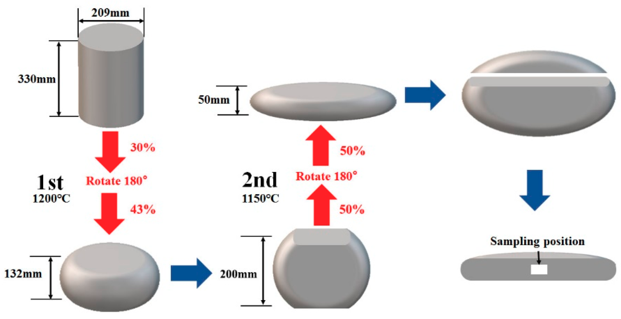
2. Materials and Methods

In the present study, the beta–gamma TiAl-based alloy with a nominal composition of Ti-44Al-4Nb-1.5Cr-0.1Mo-0.1B (at.%) was prepared by double vacuum consumable arc melting and then hot isostatically pressed (HIP) at 1300 °C under 180 MPa for 2 h followed by furnace cooling (FC). As shown in Figure 1, the cylindrical sample (Φ 209 mm × 330 mm) was preheated at 1200 °C for 6 h, and then immediately isothermal forged (ISF) at 1070 °C twice with a rotation of 180° before the second compression, with a total strain of 60% at a rate of 0.005 s−1, followed by air cooling (AC). Another 75% strain with the same process as the previous ISF was imposed on the forged cake after it was rotated 90° and preheated at 1150 °C for 6 h. Annealing was finally performed on the forged cake at 1000 °C for 2 h, followed by FC to 800 °C and AC to room temperature. Specimens of the isothermally forged plate from the white zone in Figure 1 were cut to a dimension of approximately 10 × 8 × 2 mm. The samples coated with high temperature paint (K-01 glass slurry) were heated at several selected temperature, followed by AC. Electro-polishing of specimens for light microscope (LM) and scanning electron microscope (SEM) observations was performed in a solution of 6% perchloric acid, 34% n-butyl alcohol, and 60% methanol electrolyte at 45 V and −30°C. The surface for LM observations was etched in a hydro-solution containing 3 vol.% HF and 5 vol.% HNO3. X-ray diffraction (XRD, Rigaku D/Max-2550) with Cu Kα radiation (λ = 1.5418 Å) was used to identify the phases at 50 kV and 200 mA with diffraction angles (2θ) from 10° to 100° with a step size of 0.02° and 1 s in each step. SEM (Nano SEM 450, FEI Company, Hillsboro, OR, USA), transmission electron microscopy (TEM; Tecnai G2 S-Twin F20, FEI Company, Hillsboro, OR, USA), high-resolution transmission electron microscopy (HRTEM), high-angle annular dark-field scanning transmission electron microscopy (HAADF-STEM; E.A. Fischione Instruments, Westmoreland, PA, USA) and energy-dispersive X-ray spectroscopy (EDS) were conducted on the samples to identify the mechanisms of phase transformation. Thin foils for TEM were prepared through mechanical polishing to a thickness of 100–120 μm and then twin-jet electro-polishing with a solution of 6% perchloric acid, 34% n-butyl alcohol, and 60% methanol electrolyte at 45 V and −30 °C. The hardness of samples was tested using a Vickers hardness tester (HVS-1000A; Huayin, Laizhou, Shandong, China) with a load of 4.9 N for 12 s.

3. Results and Discussion

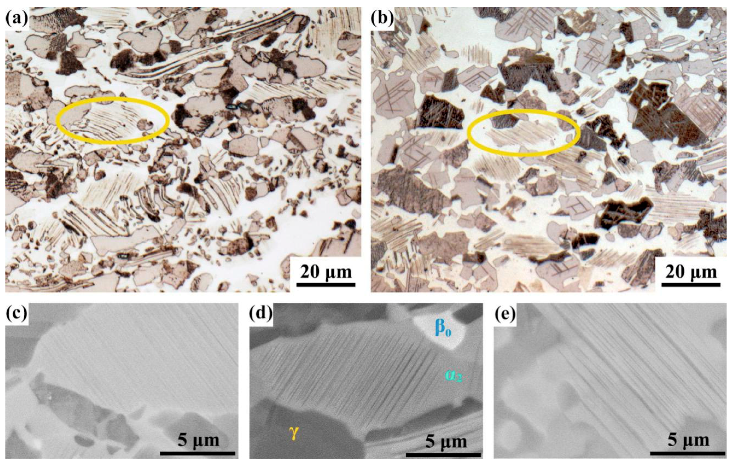
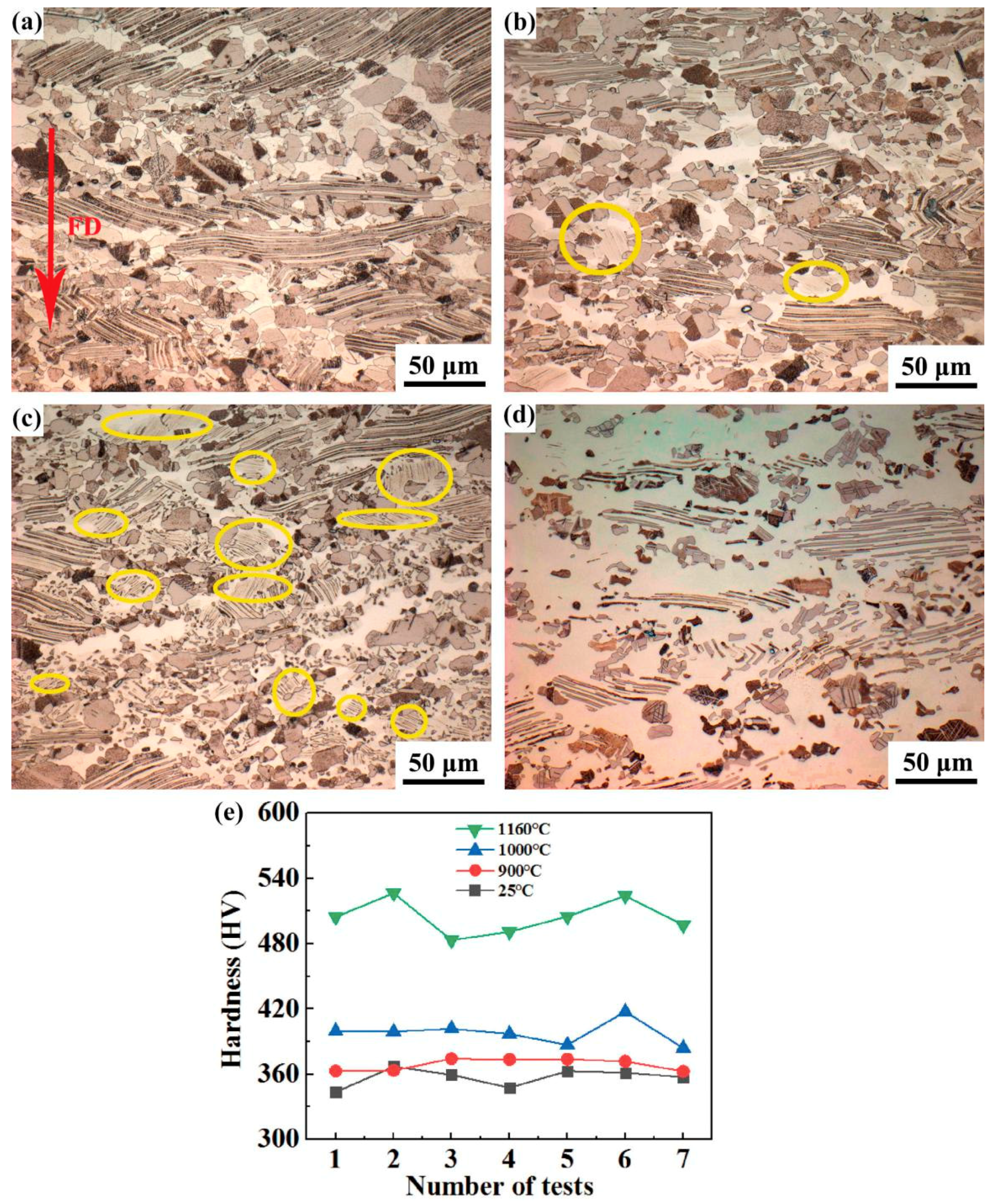
3.1. Microstructure Analysis of Forged Samples before and after Heat Treatment (HT)

As seen from Figure 2a, the microstructure of the isothermally forged alloy consists of fine grains and γ/α2 lamellar colonies. The γ/α2 lamellar colonies were twisted or broken due to isothermal forging, and the remaining broken lamellae seemed to extend perpendicular to the last-step forging direction. Similar results were reported in [11]. After heating at 900 °C for 6 h, it can be seen from Figure 2b that the microstructure of the forged alloy has hardly changed, suggesting good thermal stability. Moreover, a new kind of acicular lamellae, which were a little blurry, appeared in some grains circled in yellow. Figure 2c shows the microstructure of sample after heating at 1000 °C for 1 h, where two obvious changes occurred: (i) A lot of smaller grains with a diameter of <5 μm appeared in the areas of initial equiaxed grains, and (ii) More acicular lamellae, circled in Figure 2c, were extensively presented in the alloy. The newly-precipitated lamellae (NPL) were thinner than the initial lamellae and were not twisted. However, they were not observed in the sample after heating at 1160 °C for 1h (Figure 2d), where the structure has vanished obviously.
Figure 2e shows the hardness values of the four samples, each of which has been tested seven times. On the whole, the hardness of the forged sample tended to increase with increasing heating temperature. Specifically, the hardness of the sample heated at 900 °C for 6 h was very close to that of the sample without experiencing heating, which was consistent with the microstructural observation above. As the microstructure changed from 1000 to 1160 °C, the hardness increased more obviously. It has been reported that the relationship among the hardness values of the three phases in the alloy was βo > α2 > γ [12]. This suggests that the content of γ phase in the forged sample was more likely to be reduced if phase transformation occurred during the heat treatment and caused the hardness to increase.

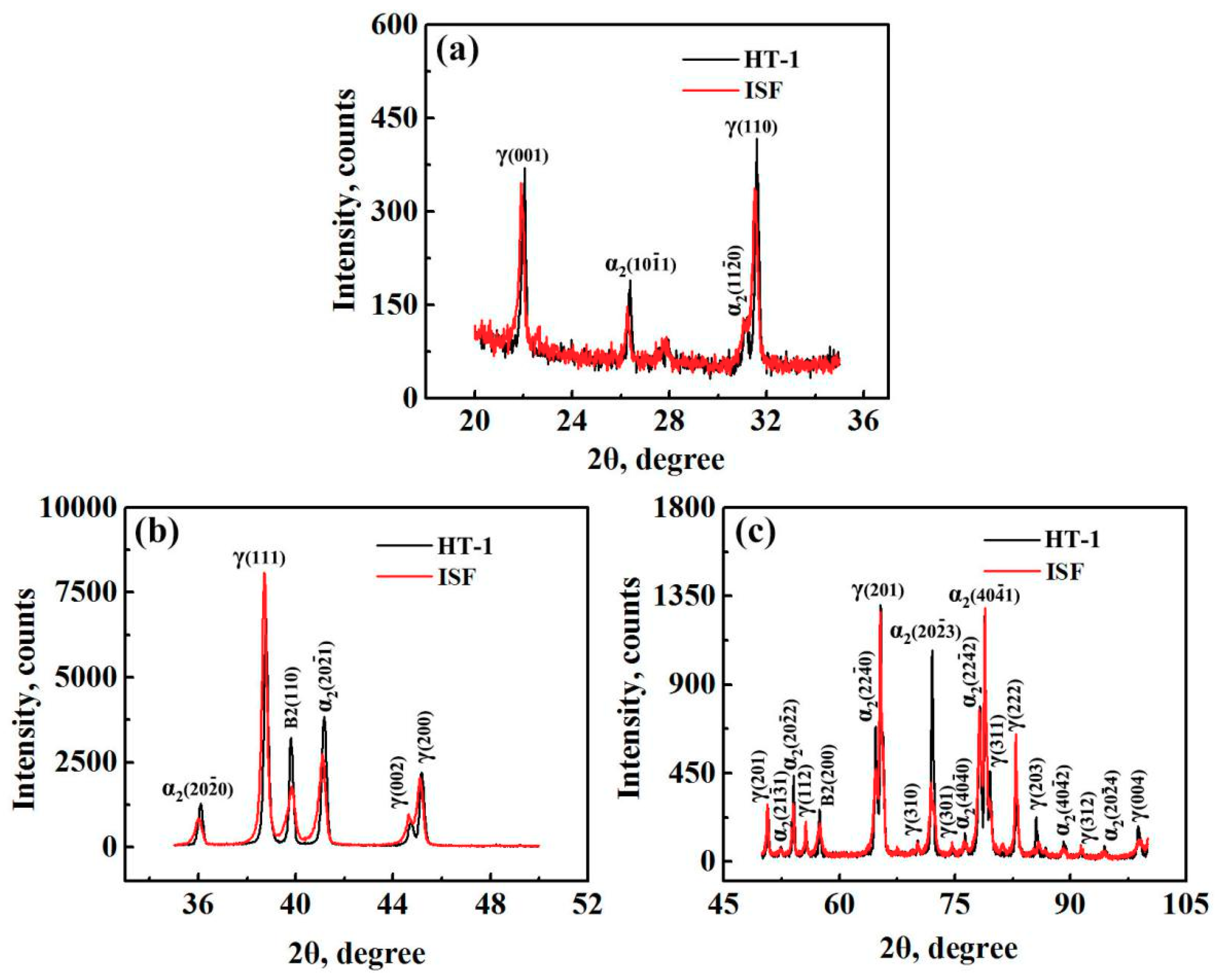
3.2. Phase Transformation Studied with XRD

Since obvious microstructural change occurred in the sample heated at 1000 °C, which was close to the upper limit of the service temperature of TiAl alloy, the forged sample heated at 1000 °C for 1 h (HT-1) was selected to compare with the initial forged sample. Significant changes are observed via XRD after HT-1. As shown in Figure 3, after heating the intensity increased for γ(001), γ(110), γ(203) and γ(004), while decreased for γ(111), γ(201), γ(112) and γ(222) and changed little for others. Almost all the intensities of α2 phase increased except for α2(11 2 ¯ 0), which was separated from γ(110) with almost no change. As for the intensity of B2 phases, both B2(110) and B2(200) peaks increased after HT-1. Generally, XRD diffraction intensity will increase as the phase content increases. Therefore, the content of α2 phase and B2 phase increased after HT-1. Since only three kinds of phases can be identified in the alloy, it can be inferred that the total amount of γ phase decreased even if the intensity of some peaks increased, which is consistent with the three highest peaks of α2, γ and B2 lying in-between 35–45°, suggesting that the refinement of grains in Figure 2c is actually a result of the dissolution of γ grains through γ → α2 + B2.
The rate of phase transformation will be very slow when the temperature is below Tmin [13]. Since the forged cake was heated at 1150 °C for 6 h before the final-step forging (which lasted almost 160 s), and then was directly air-cooled after forging at 1070 °C, there was no sufficient time for the atomic diffusion to reach equilibrium considering its large size. In theory, only if the effect of temperature on the phase transition is considered, γ lamellae should have been precipitated from the α2 phase [14] and increased during heating at 1000 °C through α 2 s s → α2 + γ according to the phase diagram [4]. This was actually confirmed since it happened in the small pieces in the heating process in the later part of this study. Then, the occurrence of γ → α2 + B2 phase transition during heat treatment at 1000 °C is an abnormal phenomenon. During forging at high temperature, stress-induced phase transformation, mainly including γ → α2, α2 → γ and α2 → B2, will occur in the TiAl-based alloy [8,15,16]. In the (α + γ + β/B2) phase field, different strain amounts lead to different fractions of phases, and the fraction of γ phase increases with increasing strain at the same temperature [11,17]. In other words, the atomic diffusion caused by stress-induced phase transformation in a short time is faster than that caused by temperature, and α2 → γ transformation may be easier and faster than γ → α2. However, there is no direct evidence to prove this up to now.

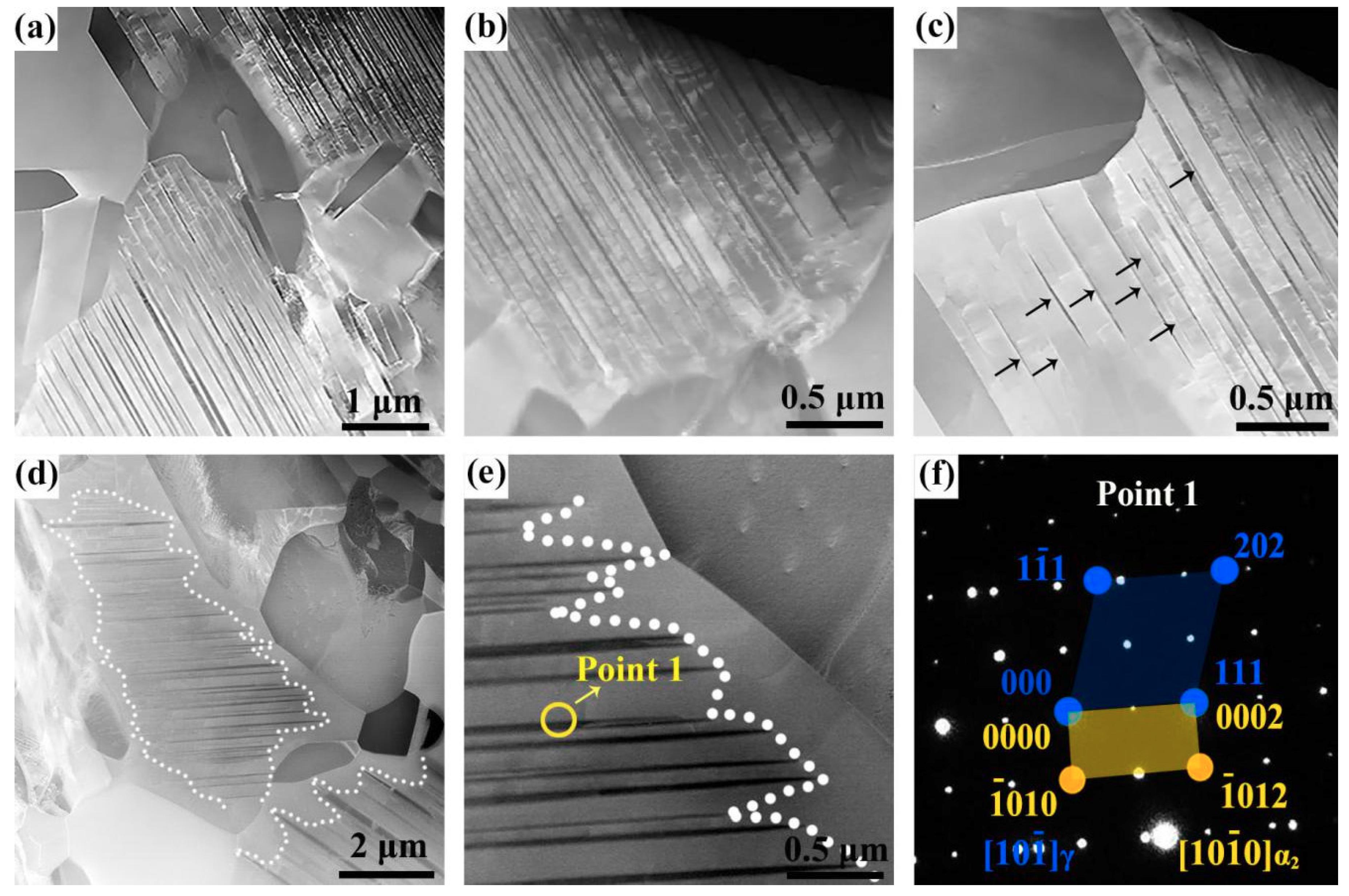
3.3. Analysis of Newly Precipitated γ Lamellae

To study the precipitation mechanism of lamellae at 1000 °C, a forged sample heated at 1000 °C for 24 h (HT-24) was used to compare with the sample HT-1. As circled in Figure 4a,b, the NPL became denser and clearer after heating at 1000 °C for 24 h. Figure 4c,d and e show the BSE (backscattered electron) images of α2 grains in the initial forged sample and the samples of HT-1 and HT-24, where the dark phase is γ phase, the gray one is α2 phase, and the white one is B2 phase. The NPL were not obvious in the initial forged TiAl (Figure 4c) and coarsened at heating process (Figure 4d,e). In a word, it is beneficial to keep the forged sample heated at 1000 °C for the precipitation of lamellae.
Figure 5a–c shows the high-angle annular dark-field (HAADF) image of NPL in α2 grains observed in the initial forged sample. The precipitated lamellae are parallel to each other and are less than 100 nm in thickness, which cannot be observed under LM. The nano-thickness NPL in α2 grains may be formed by the previous annealing after forging. Most of the NPL almost reach the grain boundary (Figure 5a), but it can be seen that the NPL near the grain boundary are finer and somewhat needle-like. Some NPL cannot reach the grain boundary of α2 grains, and the density in the interior of α2 grain is larger than that near the grain boundary (Figure 5b). The coarsest part of NPL is inside the grain and both ends of some NPL did not reach the grain boundary, as indicated by the arrows in Figure 5c. It follows that NPL first appeared inside the α2 grains rather than the grain boundary, which is different from the mechanism reported in [18]. After heating at 1000 °C for 1 h, the grains of α2 phase grew up by devouring the γ grains, resulting in both ends of NPL being farther away from the grain boundary, which can be seen in Figure 5d. Interestingly, the NPL inside the grain were not swallowed by the α2 phase but thicker than those before the heat treatment (Figure 5e). This means that NPL were continuously precipitated inside the α2 grains while α2 grains devoured γ grains, that is, α2 → γ and γ → α2 phase transformations occurred simultaneously or dynamically in the process of heat treatment. Figure 5f shows a selected area electron diffraction (SAED) pattern of position 1 in Figure 5e under TEM, revealing that the NPL and the parent phase maintain the Blackburn relationship: (111)γ// ( 0001 ) α 2 .

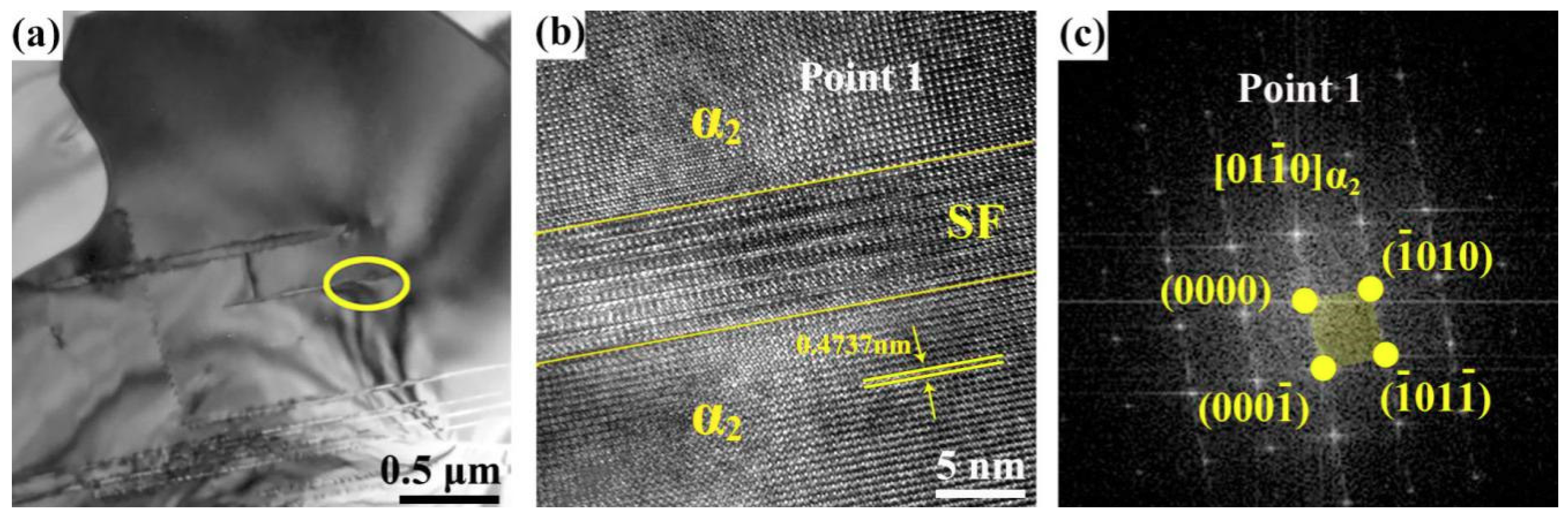
3.4. Atomic Diffusion in HT-1 Sample

EDX analysis under HADDF was performed in the samples before and after heat treatment, with at least three points in each phase determined. As seen from Table 1, after heat treatment the concentration of Al increased in α2 phase, and decreased in equiaxed γ phase. The concentration difference may provide a driving force for γ → α2 in the heating process at 1000 °C. However, the atomic percent of NPL inside α2 grains increased slightly, which is different from the equiaxed γ grains. This means that the NPL have nothing to do with the initial equiaxed γ grains and are not precipitated from grain boundaries. Thus, the increase of Al concentration in α2 phase should be the only reason to promote the precipitation and coarsening of γ lamellae (Figure 5e), except that the stacking fault itself can easily cause the segregation of solute elements. The higher Al concentration in the equiaxed γ grains of the initial forged sample may be attributed to a stress-induced phase transition, which needs further study.

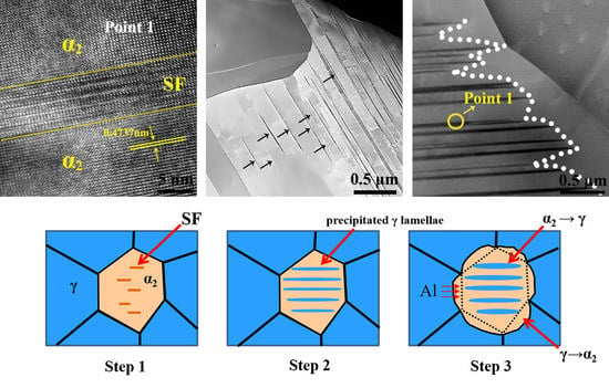
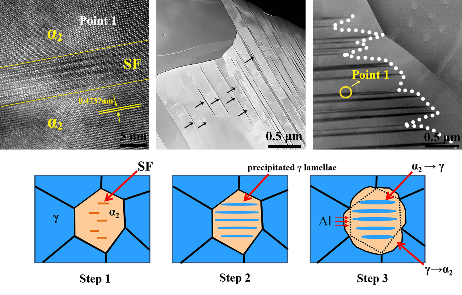
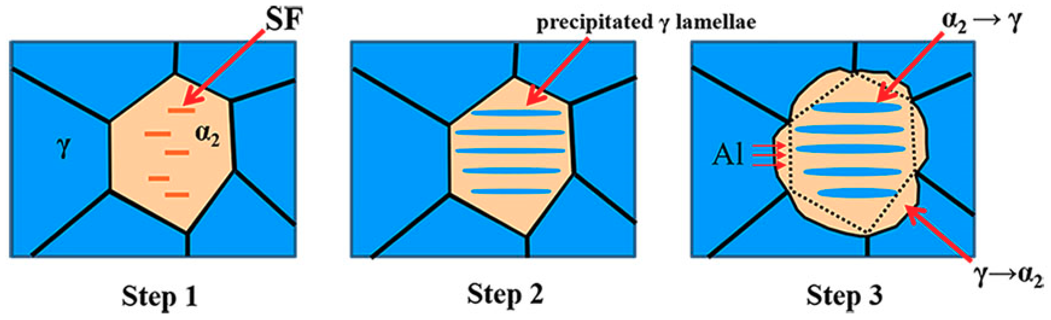
3.5. Mechanisms of Dynamic Phase Transformation

Figure 6a shows the TEM image of NPL in the sample after heat treatment. To figure out the precipitation mechanism of γ lamellae, the portion of a relatively thin and short precipitated lamella circled in Figure 6a was observed via HRTEM. As shown in Figure 6b, this lamella is not γ phase but a stacking fault of α2 phase. Figure 6c shows the Fast Fourier Transformation (FFT) image of α2 phase (point 1 in Figure 6b). It has been reported that the nucleation of γ-lamellae proceeds from grain boundaries or stacking faults on the (0001)α2 basal plane [14]. There are lots of different points of view on the formation mechanism of stacking faults in α2 phase [19,20,21,22], where the main view is that stacking faults originate from grain boundaries or are caused by the cross-slip of Shockley dislocations from grain boundaries to basal planes [23]. Due to the order-disorder phase transition of α2 → α, the c/a ratio of α2-phase decreases when the temperature approaches or exceeds Tmin (being 1160 °C) [24], which may be another reason for the formation of stacking faults in α2 phase. Once the internal stacking faults of α2 phase are formed, the element segregation would occur near them at a high temperature. This is also the reason why lamellae can be precipitated when the concentration of Al in α2 phase is low (Table 1). The newly grown areas of α2 grains in the heating process at 1000 °C (Figure 5d,e) do not experience the process of forging or order-disorder phase transition, thus there are no conditions for stacking faults to form in these freshly grown areas. Besides, the newly formed α2 phase is close to the equilibrium state at 1000 °C, so the element supersaturation is absent there. It follows that NPL do not continue to extend after heat treatment, but only coarsen after reaching the original grain boundary, as shown by the dotted curves in Figure 5d,e.
Figure 7 shows the whole process of phase transformations of α2 ↔ γ observed in this study. First, a large number of stacking faults occur inside α2 grains in the process of forging or order-disorder phase transition of α → α2. Second, Al atoms in the α2 grains are preferred to migrate into the stacking faults, forming the nano-thickness lamellae under the action of temperature after forging. Third, when heated to 1000 °C, Al atoms in γ grains migrate into α2 grains, causing γ grains to be dissolved and gradually transformed into α2 phase, and the Al atoms entering the α2 phase will further gather at the stacking faults of α2 phase and newly formed γ lamellae, which promotes the precipitation and coarsening of the γ lamellae in the α2 grains.

4. Conclusions

The microstructure of the forged beta–gamma intermetallic alloy changed obviously because of phase transformation when heating in the range of 1000–1160 °C, leading to the increase in the hardness with increasing heating temperature. The stress-induced phase transformation in the forging process decreased the concentration of Al in α2 grains and increased the volume fraction of γ phase in a short time, providing a driving force for the dissolution of γ-phase in the forged TiAl-based alloy through γ → α2 + B2 phase transformation when heated at 1000 °C, which was a result of decomposition of Al in γ grains. The precipitation of γ lamellae in the α2 grains through α2 → γ was due to the preferential enrichment of Al at stacking faults. In a word, the dynamic phase transformations of α2 → γ and γ → α2 occur simultaneously.

Author Contributions

S.Q., A.F, and J.S. designed and supervised the project, and produced the samples; Z.Z. conducted the experiments under the guidance of S.Q., A.F., J.S, and D.C.; All the authors analyzed the data and discussed the results; Z.Z. wrote the initial manuscript; S.Q., A.F., G.C., and D.C. revised and edited the article.

Funding

This research was funded by the National Natural Science Foundation of China (NSFC), Grant Number: 51871168, and the Natural Sciences and Engineering Research Council of Canada (NSERC) in the form of international research collaboration.

Conflicts of Interest

The authors declare no conflict of interest.

References

  1. Appel, F.; Paul, J.; Oehring, M. Gamma Titanium Aluminides: Science and Technology; Wiley-VCH Verla GmbH &Co. KGaA: Weinheim, Germany, 2011; pp. 1–30. [Google Scholar]
  2. Wu, G.D.; Cui, G.R.; Qu, S.J.; Feng, A.H.; Cao, G.J.; Ge, B.H.; Xiang, H.P.; Shen, J.; Chen, D.L. High-temperature oxidation mechanisms of nano-/submicro-scale lamellar structures in an intermetallic alloy. Scripta Mater. 2019, 171, 102–107. [Google Scholar] [CrossRef]
  3. Qu, S.J.; Tang, S.Q.; Feng, A.H.; Feng, C.; Shen, J.; Chen, D.L. Microstructural evolution and high-temperature oxidation mechanisms of a titanium aluminide based alloy. Acta Mater. 2018, 148, 300–310. [Google Scholar] [CrossRef]
  4. Qiu, C.; Liu, Y.; Zhang, W.; Liu, B.; Liang, X. Development of a Nb-free TiAl-based intermetallics with a low-temperature superplasticity. Intermetallics 2012, 27, 46–51. [Google Scholar] [CrossRef]
  5. Huang, Z.W. Thermal stability of Ti-44Al-4Nb-4Hf-0.2Si-1B alloy. Intermetallics 2013, 37, 11–21. [Google Scholar] [CrossRef]
  6. Schwaighofer, E.; Clemens, H.; Mayer, S.; Lindemann, J.; Klose, J.; Smarsly, W.; Güther, V. Microstructural design and mechanical properties of a cast and heattreated intermetallic multi-phase γ-TiAl-based alloy. Intermetallics 2014, 44, 128–140. [Google Scholar] [CrossRef]
  7. Huang, Z.W.; Lin, J.P.; Sun, H.L. Microstructural changes and mechanical behaviour of a near lamellar γ-TiAl alloy during long-term exposure at 700 °C. Intermetallics 2017, 85, 59–68. [Google Scholar] [CrossRef]
  8. Derder, C.; Bonnet, R.; Pe´nisson, J.M.; Frommeyer, G. Evidence of stress-induced α2 → γ transformation in a Ti-30 at.%Al alloy. Scripta Mater. 1997, 38, 757–762. [Google Scholar] [CrossRef]
  9. Zhang, W.J.; Lorenz, U.; Appel, F. Recovery, recrystallization and phase transformations during thermomechanical processing and treatment of TiAl-based alloys. Acta Mater. 2000, 48, 2803–2813. [Google Scholar] [CrossRef]
  10. Zhu, K.; Qu, S.J.; Feng, A.H.; Sun, J.L.; Shen, J. Microstructural evolution and refinement mechanism of a beta–gamma TiAl-based alloy during multidirectional isothermal forging. Materials 2019, 12, 2496. [Google Scholar] [CrossRef]
  11. Zhu, K.; Qu, S.J.; Feng, A.H.; Sun, J.L.; Shen, J. Evolution of the microstructure and lamellar orientation of a β-Solidifying γ-TiAl-based alloy during hot compression. Metals 2018, 8, 445. [Google Scholar] [CrossRef]
  12. Schloffer, M.; Iqbal, F.; Gabrisch, H.; Schwaighofer, E.; Schimansky, F.P.; Mayer, S.; Stark, A.; Lippmann, T.; Göken, M.; Pyczak, F.; et al. Microstructure development and hardness of a powder metallurgical multi phase γ-TiAl-based alloy. Intermetallics 2012, 22, 231–240. [Google Scholar] [CrossRef]
  13. Erdely, P.; Werner, R.; Schwaighofer, E.; Clemens, H.; Mayer, S. In-situ study of the time-temperature-transformation behaviour of a multi-phase intermetallic β-stabilised TiAl alloy. Intermetallics 2015, 57, 17–24. [Google Scholar] [CrossRef]
  14. Wei, D.X.; Koizumi, Y.; Nagasako, M.; Chiba, A. Refinement of lamellar structures in Ti-Al alloy. Acta Mater. 2017, 125, 81–97. [Google Scholar] [CrossRef]
  15. Du, X.W.; Zhu, J.; Zhang, X.; Cheng, Z.Y.; Kim, Y.W. Creep induced α2 → B2 phase transformation in a fully-lamellar TiAl alloy. Scripta Mater. 2000, 43, 597–602. [Google Scholar] [CrossRef]
  16. Wang, J.G.; Chen, G.L.; Zhang, L.C.; Ye, H.Q. Study on the stress-induced γ + α2 transformation in a hot-deformed Ti-45Al-10Nb alloy by high-resolution transmission electron microscopy. Mater. Lett. 1997, 31, 179–183. [Google Scholar] [CrossRef]
  17. Liu, S.Q.; Shen, J. Microstructural evolution and high-temperature oxidation mechanisms of a titanium aluminide based alloy. Mater. Res. Express 2018, 5, 096516. [Google Scholar] [CrossRef]
  18. Qin, G.W.; Hao, S.; Sun, X.D. Ledge mechanism of primary α2/γ lamellae growing in the supersaturated α2 matrix for γ-TiAl-based (γ +α2) alloy. Scripta Mater. 1998, 39, 289–293. [Google Scholar] [CrossRef]
  19. Zghal, S.; Thomas, M.; Naka, S.; Finel, A.; Couret, A. Phase transformations in TiAl-based alloys. Acta Mater. 2005, 53, 2653–2664. [Google Scholar] [CrossRef]
  20. Denquin, A.; Naka, S. Phase transformation mechanisms involved in two-phase TiAl-based alloys-Ⅱ. discontinuous coarsening and massive-type transformation. Acta Mater. 1996, 44, 353–365. [Google Scholar] [CrossRef]
  21. Denquin, A.; Naka, S. Phase transformation mechanisms involved in two-phase TiAl-based alloys-Ⅰ, lamellar structure formation. Acta Mater. 1996, 44, 343–352. [Google Scholar] [CrossRef]
  22. Karadge, M.; Gouma, P.; Philos, I. A structural aspect of α(α2) → lamellar α2 + γ transformation in γ-TiAl. Mag. Lett. 2006, 84, 451–459. [Google Scholar]
  23. Koizumi, Y.; Fujita, T.; Minamino, Y.; Hata, S. Effects of plastic deformation on lamellar structure formation in Ti-39 at.% Al single crystals. Acta Mater. 2010, 58, 1104–1115. [Google Scholar] [CrossRef]
  24. Yeoh, L.A.; Liss, K.D.; Bartels, A.; Chladil, H.; Avdeev, M.; Clemens, H.; Gerling, R.; Buslaps, T. In situ high-energy X-ray diffraction study and quantitative phase analysis in the α + γ phase field of titanium aluminides. Scripta Mater. 2007, 57, 1145–1148. [Google Scholar] [CrossRef]
Figure 1. Schematic diagram of the two-step multi-directional isothermal forging and sampling position in the forged plate.
Materials 12 02787 g001
Figure 2. Microstructure of isothermally forged TiAl samples in different states: (a) forged sample; (b) heating at 900 °C for 6 h; (c) heating at 1000 °C for 1 h; (d) heating at 1160 °C for 1 h. The last-step isothermal forging direction (FD) is marked (a); (e) the hardness of the forged samples in various conditions corresponding to samples (ad).
Materials 12 02787 g002
Figure 3. Comparison of X-ray diffraction (XRD) patterns between the samples in the states of isothermal forging (ISF) and isothermal forging + 1000 °C/1 h/AC (HT-1) (a) 20° < 2θ < 35°; (b) 35° < 2θ < 50°; (c) 50° < 2θ < 100°.
Materials 12 02787 g003
Figure 4. Light microscope (LM) images (a,b) and BSE images (ce) of newly precipitated lamellae in the forged samples of HT-1 (a,d), HT-24 (b,e) and sample with no heating process (c).
Materials 12 02787 g004
Figure 5. The high-angle annular dark-field (HAADF) images of initial isothermally forged TiAl (ac) and HT-1 (d,e), where (f) is the selected area diffraction pattern from location 1 in (e).
Materials 12 02787 g005
Figure 6. (a) Transmission electron microscopy (TEM) image of precipitated lamellae in the interior of α2 grain, (b) high-resolution transmission electron microscopy (HRTEM) image of stacking faults, (c) Fast Fourier Transformation (FFT) pattern of point 1 in (b).
Materials 12 02787 g006
Figure 7. Schematic illustration of phase transitions α2 ↔ γ proposed in this study.
Materials 12 02787 g007
Table 1. Atomic percent (at.%) of Ti and Al elements in α2 phase and γ phase in the isothermally forged TiAl alloy and the isothermally forged sample after heat treatment at 1000 °C for 1 h.
Stateα2 Phaseγ Phase
Equiaxed GrainsPrecipitated Lamellae
TiAlTiAlTiAl
ISF64.335.747.752.349.150.9
ISF + 1000 °C/1 h/AC60.239.848.951.148.251.8

