Application of Small Specimen Test Technique to Evaluate Creep Behavior of Austenitic Stainless Steel

 ,
,
Abstract
:
1. Introduction
2. Experimental Details
3. Results and Discussion
4. Conclusions
Author Contributions
Funding
Conflicts of Interest
References
- Konings, R. Comprehensive Nuclear Materials; Elsevier: Amsterdam, The Netherlands, 2011. [Google Scholar]
- Lucas, G.E.; Odette, G.R.; Matsui, H.; Möslang, A.; Spätig, P.; Rensman, J.; Yamamoto, T. The role of small specimen test technology in fusion materials development. J. Nucl. Mater. 2007, 367–370, 1549–1556. [Google Scholar] [CrossRef]
- Han, W.; Yabuuchi, K.; Kasada, R.; Kimura, A.; Wakai, E.; Tanigawa, H.; Liu, P.; Yi, X.; Wan, F. Application of small specimen test technique to evaluate fracture toughness of reduced activation ferritic/martensitic steel. Fusion Eng. Des. 2017, 125, 326–329. [Google Scholar] [CrossRef]
- Lucas, G.E.; Odette, G.R.; Sokolov, M.; Spätig, P.; Yamamoto, T.; Jung, P. Recent progress in small specimen test technology. J. Nucl. Mater. 2002, 307–311, 1600–1608. [Google Scholar] [CrossRef]
- Wakai, E.; Nogami, S.; Kasada, R.; Kimura, A.; Kurishita, H.; Saito, M.; Ito, Y.; Takada, F.; Nakamura, K.; Molla, J.; et al. Small specimen test technology and methodology of IFMIF/EVEDA and the further subjects. J. Nucl. Mater. 2011, 417, 1325–1330. [Google Scholar] [CrossRef]
- Hyde, T.H.; Sun, W.; Hyde, C.J. An Overview of Small Specimen Creep Testing, Advanced Materials Modelling for Structures; Springer: Berlin/Heidelberg, Germany, 2013; pp. 201–216. [Google Scholar]
- Hyde, T.H.; Sun, W.; Williams, J.A. Requirements for and use of miniature test specimens to provide mechanical and creep properties of materials: A review. Int. Mater. Rev. 2007, 52, 213–255. [Google Scholar] [CrossRef]
- Dyson, C.C.; Sun, W.; Hyde, C.J.; Brett, S.J.; Hyde, T.H. Use of small specimen creep data in component life management: A review. Mater. Sci. Technol. 2016, 32, 1567–1581. [Google Scholar] [CrossRef]
- Jianu, A.; Müller, G.; Weisenburger, A.; Heinzel, A.; Fazio, C.; Markov, V.G.; Kashtanov, A.D. Creep-to-rupture tests of T91 steel in flowing Pb-Bi eutectic melt at 550 °C. J. Nucl. Mater. 2009, 394, 102–108. [Google Scholar] [CrossRef]
- Yurechko, M.; Schroer, C.; Wedemeyer, O.; Skrypnik, A.; Konys, J. Creep-rupture tests on chromium-containing conventional and ODS steels in oxygen-controlled Pb and air at 650 C. Nucl. Eng. Des. 2014, 280, 686–696. [Google Scholar] [CrossRef]
- Segle, P.; Tu, S.T.; Storesund, J.; Samuelson, L.Å. Some issues in life assessment of longitudinal seam welds based on creep tests with cross-weld specimens. Int. J. Press. Vessel. Pip. 1996, 66, 199–222. [Google Scholar] [CrossRef]
- Krompholz, K.; Kalkhof, D. Size effect studies of the creep behaviour of a pressure vessel steel at temperatures from 700 to 900 °C. J. Nucl. Mater. 2002, 305, 112–123. [Google Scholar] [CrossRef]
- Das, A.; Tarafder, S. Geometry of dimples and its correlation with mechanical properties in austenitic stainless steel. Scr. Mater. 2008, 59, 1014–1017. [Google Scholar] [CrossRef]
- Srivastava, A.; Gopagoni, S.; Needleman, A.; Seetharaman, V.; Staroselsky, A.; Banerjee, R. Effect of specimen thickness on the creep response of a Ni-based single-crystal superalloy. Acta Mater. 2012, 60, 5697–5711. [Google Scholar] [CrossRef]
- Gussev, M.; Busby, J.; Field, K.; Sokolov, M.A.; Gray, S.E. Role of Scale Factor During Tensile Testing of Small Specimens. In Small Specimen Test Techniques: 6th Volume; Sokolov, M., Lucon, E., Eds.; ASTM International: West Conshohocken, PA, USA, 2015; pp. 31–49. [Google Scholar]
- Dai, Y.; Egeland, G.W.; Long, B. Tensile properties of EC316LN irradiated in SINQ to 20 dpa. J. Nucl. Mater. 2008, 377, 109–114. [Google Scholar] [CrossRef]
- Dai, Y.; Jia, X.; Thermer, R.; Hamaguchi, D.; Geissmann, K.; Lehmann, E.; Linder, H.P.; James, M.; Gröschel, F.; Wagner, W.; et al. The second SINQ target irradiation program, STIP-II. J. Nucl. Mater. 2005, 343, 33–44. [Google Scholar] [CrossRef]
- ISO 204. Metallic Materials—Uniaxial Creep Testing in Tension—Method of Test; ISO: Geneva, Switzerland, 2009. [Google Scholar]
- Kassner, M.E. Fundamentals of Creep in Metals and Alloys; Butterworth-Heinemann: Amsterdam, The Netherlands, 2015. [Google Scholar]
- Leinster, M.G. A method of creep rupture data extrapolation based on physical processes. Int. J. Press. Vessel. Pip. 2008, 85, 701–710. [Google Scholar] [CrossRef]
- Monkman, F.C.; Grant, F.J. An empirical relationship between rupture life and minimum creep rate in creep-rupture tests. Proc. ASTM 1956, 56, 593–620. [Google Scholar]
- Povolo, F. Comments on the Monkman-Grant and the modified Monkman-Grant relationships. J. Mater. Sci. 1985, 20, 2005–2010. [Google Scholar] [CrossRef]
- Latha, S.; Mathew, M.D.; Parameswaran, P.; Rao, K.B.S.; Mannan, S.L. Creep behaviour of 14Cr-15Ni-Ti stainless steel at 923K. Mater. Sci. Eng. A 2010, 527, 5167–5174. [Google Scholar] [CrossRef]
- Larson, F.R.; Miller, J. A time-temperature relationship for rupture and creep stresses. Trans. ASME 1952, 74, 765–775. [Google Scholar]
- Strafella, A.; Coglitore, A.; Fabbri, P.; Salernitano, E. 15-15Ti(Si) austenitic steel: Creep behaviour in hostile environment. Frat. Integr. Strutt. 2017, 11, 352–365. [Google Scholar] [CrossRef]
- Radzikowska, J.M. Metallography and Microstructures of Cast Iron. In Metallography and Microstructures; Volume 9, ASM Handbook; ASM: Russell Town, Geauga County, OH, USA, 2004; pp. 565–587. [Google Scholar]
- Miura, N.; Harada, N.; Kondo, Y.; Okabe, M.; Matsuo, T. Stress Exponent of Minimum Creep Rate and Activation Energy of Creep for Oxide Dispersion-strengthened Nickel-based Superalloy MA754. ISIJ Int. 2012, 52, 140–146. [Google Scholar] [CrossRef] [Green Version]
- Zakine, C.; Prioul, C.; François, D. Creep behaviour of ODS steels. Mater. Sci. Eng. A 1996, 219, 102–108. [Google Scholar] [CrossRef]
- Frost, H.J.; Ashby, M.F. Deformation Mechanism Maps: The Plasticity and Creep of Metals and Ceramics; Pergamon Press: Oxford, UK, 1982. [Google Scholar]
- Park, J.G.; Lee, D.Y. Creep behavior of AISI 316 stainless steel above 0.5 TM. Scr. Metall. Mater. 1993, 29, 595–598. [Google Scholar] [CrossRef]
- Pilloni, G.; Quadrini, E.; Spigarelli, S. Interpretation of the role of forest dislocations and precipitates in high-temperature creep in a Nb-stabilised austenitic stainless steel. Mater. Sci. Eng. A Struct. Mater. Prop. Microstruct. Process. 2000, 279, 52–60. [Google Scholar] [CrossRef]
- Han, W.; Zhan, Q.; Yi, X.; Ohnuki, S.; Liu, Y.; Liu, P.; Wan, F.; Morrall, D. Deformation behavior of austenitic stainless steel at deep cryogenic temperatures. J. Nucl. Mater. 2018, 504, 29–32. [Google Scholar] [CrossRef]


| Element | Ni | Cr | Ti | Mo | Mn | Si | C | N | P | S | V | Cu | Al | Fe |
|---|---|---|---|---|---|---|---|---|---|---|---|---|---|---|
| Concentration | 15.37 | 16.65 | 0.46 | 2.15 | 1.92 | 0.43 | 0.07 | 0.013 | 0.006 | 0.004 | 0.18 | 0.02 | 0.02 | Balance |
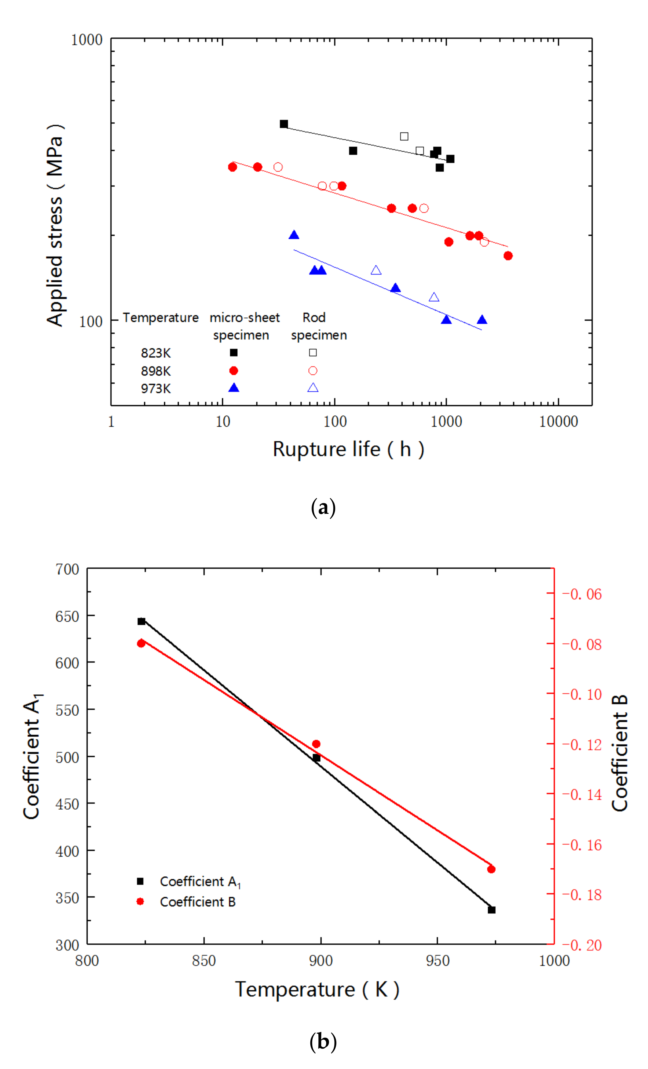
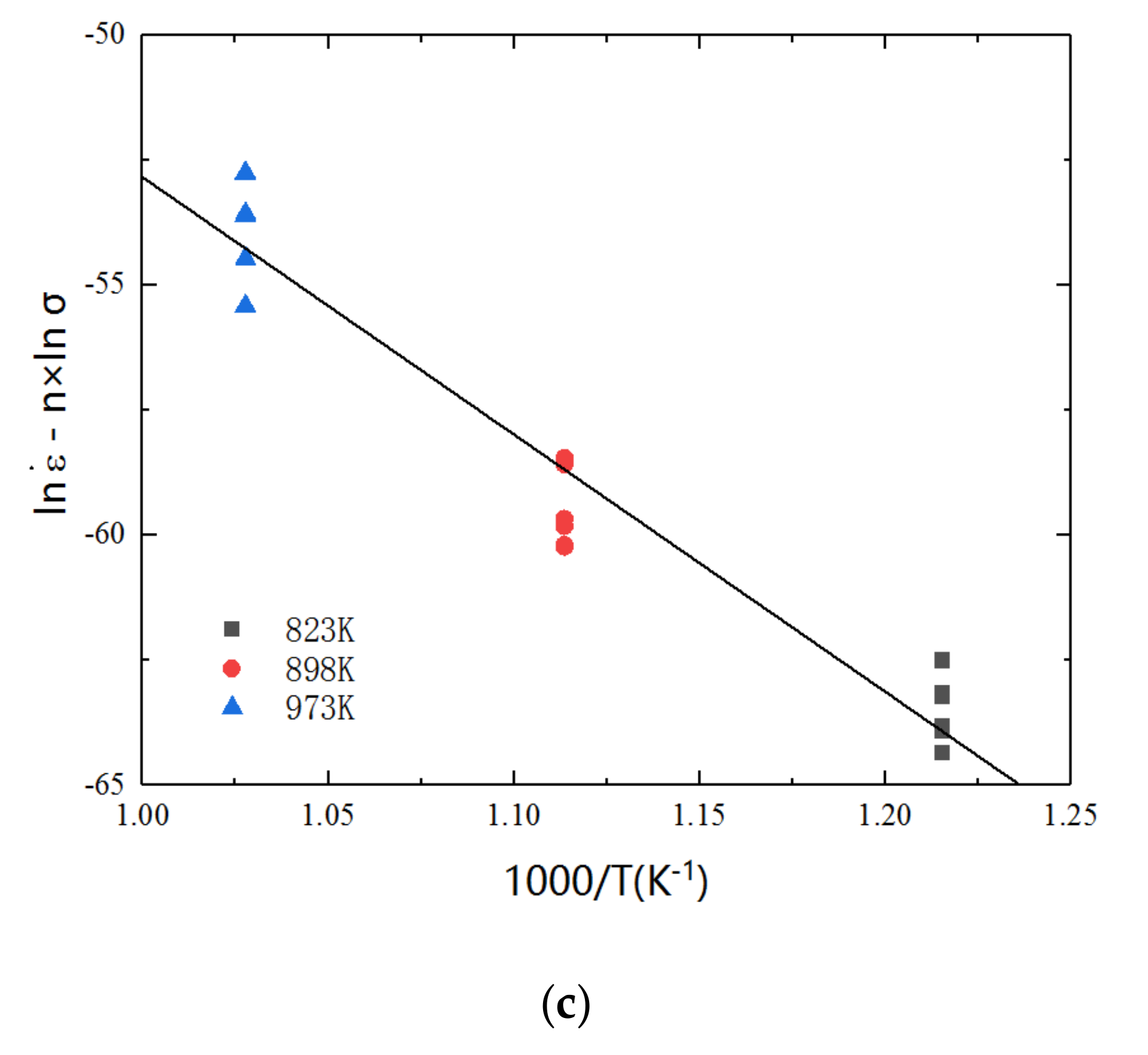
| Temperature | A1 | B |
|---|---|---|
| 823 K | 644 | −0.08 |
| 898 K | 499 | −0.12 |
| 973 K | 337 | −0.17 |
© 2019 by the authors. Licensee MDPI, Basel, Switzerland. This article is an open access article distributed under the terms and conditions of the Creative Commons Attribution (CC BY) license (http://creativecommons.org/licenses/by/4.0/).
Share and Cite
Yu, B.; Han, W.; Tong, Z.; Geng, D.; Wang, C.; Zhao, Y.; Yang, W. Application of Small Specimen Test Technique to Evaluate Creep Behavior of Austenitic Stainless Steel. Materials 2019, 12, 2541. https://doi.org/10.3390/ma12162541
Yu B, Han W, Tong Z, Geng D, Wang C, Zhao Y, Yang W. Application of Small Specimen Test Technique to Evaluate Creep Behavior of Austenitic Stainless Steel. Materials. 2019; 12(16):2541. https://doi.org/10.3390/ma12162541
Chicago/Turabian StyleYu, Bintao, Wentuo Han, Zhenfeng Tong, Diancheng Geng, Chenlong Wang, Yingchao Zhao, and Wen Yang. 2019. "Application of Small Specimen Test Technique to Evaluate Creep Behavior of Austenitic Stainless Steel" Materials 12, no. 16: 2541. https://doi.org/10.3390/ma12162541
APA StyleYu, B., Han, W., Tong, Z., Geng, D., Wang, C., Zhao, Y., & Yang, W. (2019). Application of Small Specimen Test Technique to Evaluate Creep Behavior of Austenitic Stainless Steel. Materials, 12(16), 2541. https://doi.org/10.3390/ma12162541