Article

A Random Angular Bend Algorithm for Two- Dimensional Discrete Modeling of Granular Materials

1
School of Civil Engineering, Chongqing University, Chongqing 400045, China
2
Key Laboratory of New Technology for Construction of Cities in Mountain Area, Chongqing University, Chongqing 400045, China
3
National Joint Engineering Research Center of Geohazards Prevention in the Reservoir Areas, Chongqing University, Chongqing 400045, China
*
Author to whom correspondence should be addressed.
Materials 2019, 12(13), 2169; https://doi.org/10.3390/ma12132169
Submission received: 28 May 2019 / Revised: 26 June 2019 / Accepted: 3 July 2019 / Published: 5 July 2019

Abstract

:
Generation of particles with irregular shape and the overlap detection are crucial for numerical simulation of granular materials. This paper presents a systematic approach to develop a two-dimensional random particle model for numerical simulation of granular materials. Firstly, a random angular bend (RAB) algorithm is proposed and coded in Python to simulate the geometric model of individual particle with irregular shape. Three representative parameters are used to quantitatively control the shape feature of generated polygons in terms of three major aspects, respectively. Then, the generated geometrical models are implemented into particle flow code PFC2D to construct the clump library. The clumps are created via the mid-surface method. Besides, an overlap detection algorithm is developed to address the difficulties associated with spatial allocation of irregularly shaped particles. Finally, two application examples are adopted to validate the feasibility of the proposed algorithm in the numerical modeling of realistic granular materials. The study provides a solid foundation for the generation and simulation of the granular materials based on angular bend theory.

1. Introduction

Granular materials are conglomerations of discrete solids [1], which are widely used in various engineering fields, such as geotechnical engineering, mining engineering, and food and pharmaceutical industries. Due to the discontinuous nature and irregularity of particle shape, the study of properties of granular materials remains an open issue. In the study of granular material behavior, some experimental tests were conducted to analyze the effect of particle shape and size on the mechanical and physical properties of granular materials [2,3]. However, it is difficult to precisely control particle shape and size in these tests. Besides, conventional experimental tests cannot provide sufficient microscale information of samples, such as interparticle forces, particle velocities, etc.
Overcoming the disadvantage of model test in these respects, the numerical analysis method is commonly accepted by many researchers in the last decade. The discrete element method (DEM), originally developed by Cundall in 1971 [4,5], provides a convenient way to obtain particle information on multiple scales, and gradually becomes an effective tool to study the mechanical behaviors of granular materials [6,7,8,9]. To investigate the effect of particle shape, various shapes have been created to approximate the realistic shape of particles (such as circles and spheres [10,11,12,13], ellipses and ellipsoids [14,15], cylinders [16], polygons, and polyhedrons [17,18,19]). However, a considerable number of them are idealized geometric shape, which is unable to capture the behavior of actual or natural granular materials better.
To precisely generate arbitrary-shaped particle in two-dimensional simulation, many methods have been proposed in the literature. Typical approaches include R(θ) method [20], Voronoi grain-based method [21,22], digital image-based method [23], image-based clump library method [24,25], Fourier-based method [26,27,28], etc. However, the R(θ) method is only applicable for star-like particles [29,30]. The Voronoi grain-based method has limited capability in precisely controlling generated particle shape and size. During the modeling of granular materials based on digital image technology, it is difficult to obtain digital images of the whole research area or obtain the digital images of idealized section for specified research purpose. Image-based clump library method overcomes the disadvantage of above method and provides a new method to create virtual specimens possessing various shapes and particle gradations. However, tremendous efforts are required to develop the clump library (a clump is a rigid collection of n rigid spherical pebbles, which are unit-thickness disks in PFC2D). Among various Fourier-based approaches, the shape function R(θ) based method is widely used in shape analysis and generation. However, this method is only applicable for star-like particles. For nonstar-like particles, the radial line may have multiple intersections with the boundary of particle contour [30]. Compared with the methods above, the shape function φ(l) (Z-R shape function) based method which is developed by Zahn and Roskies (1972) has distinct advantages in precisely representing the realistic particles [31]. However, there is limited research on the random generation of irregular particles based on this theory.
Inspired by the theory of Z-R shape function, this paper presents a novel method to generate two-dimensional random particle model for the numerical simulation of granular materials. The flowchart of this paper is shown in Figure 1. Firstly, a random angular bend (RAB) algorithm is proposed and coded in Python [32] to simulate the geometric model of individual particle with irregular shape. Three representative parameters are used to quantitatively control the shape feature of generated polygons in term of three major aspects, namely, the form, roundness, and surface textures, respectively. The geometric models are imported into PFC2D [33] to generate realistic granular media. Clumps consisting of pebbles are created based on the mid-surface method [34] and used to construct clump library. An overlap detection algorithm is developed to address difficulties associated with spatial allocation of irregularly shaped particles. Finally, two application examples are further employed to show the feasibility of proposed algorithm for the numerical modeling of realistic granular materials.

2. Particle Generation

2.1. Z-R Shape Function

Shape function φ(l) was introduced by Zahn and Roskies (1972) to represent the shape of closed polygonal curve in term of arc length l and cumulative angular bends φ. To describe the shape of a polygon, which is made up of n vertices P0, P1,…, Pn with angular bends Δφ0, Δφ1,…, Δφn and edge lengths Δl0, Δl1, …, Δln (as shown in Figure 2), the first thing that need to be done is to trace clockwise around the outline of the polygon from some initial starting point to collect Cartesian (x, y) coordinates [35]. Once the coordinates of all the vertices are determined, they can be used to calculate edge lengths Δli and angular bend Δφi. The clockwise arc lengths l along the curve from starting point P0 up to the ith vertex Pi is given as Equation (1)
l = k = 1 i Δ l k
Next step is to determine the angle bend Δφi between adjacent polygon segments. Taking the adjacent polygon segments as a vector, the magnitude and orientation of the angle can be determined based on vector operation. For three adjacent point, Pi-1(xi-1,yi-1), Pi (xi, yi) and Pi+1(xi+1,yi+1), the magnitude of Δφi can be calculated using the dot products of vector P i 1 P i and P i P i + 1 .
| Δ φ i | = arccos ( P i 1 P i P i P i + 1 | P i 1 P i | | P i P i + 1 | )
where | Δ φ i | is the absolute value of Δφi. The polarity of Δφi depends upon the sign of the cross products of the two vectors, which is given as the determinant of a matrix Si [36].
S i = | x i 1 y i 1 1 x i y i 1 x i + 1 y i + 1 1 |
If Si > 0, then P i P i + 1 is clockwise with respect to P i 1 P i , if Si < 0, it is counterclockwise. Once the sign of this cross product is determined, the value of Δφi can be obtained by applying the following rules.
if   S i 0 , Δ φ i = | Δ φ i | × S i | S i |
if   S i = 0 , Δ φ i = 0
where | S i | is the absolute value of Si. It should be noted that a cross product of 0 means that vector P i 1 P i and P i P i + 1 . are collinear.
The cumulative angular function φ(l), also known as Z-R shape function, is the summation of all the angular bends from vertex P0 up to the vertex Pi (corresponding to arc length l). This function is given by φ(l) = k = 1 i Δ φ k . If the outline is traced clockwise and is not spiral, the value of φ(Lall) equal to -2π, where Lall is the total length of the polygon. Throughout the above procedures described in Equations (1)–(5), the coordinates of points on the polygon are converted from their Cartesian (x,y) form to the φ(l) form of Z-R shape function [37]. Shape analysis can be conducted based on the result of Z-R shape function [31] (Figure 2).

2.2. Generation of Irregularly Shaped Polygon

Inspired by the theory of Z-R shape function, the RAB algorithm is proposed in this section and coded in Python. This method is the inverse operation and modification of the theory of Z-R shape function. As shown in Figure 3, the algorithm can be described as follows.
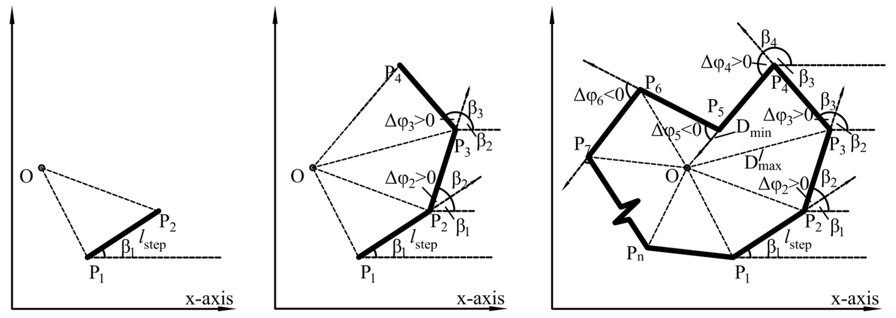
  • Define a random point O as the center and a point P1 (x1, y1) as initial starting point of the polygon to be generated.
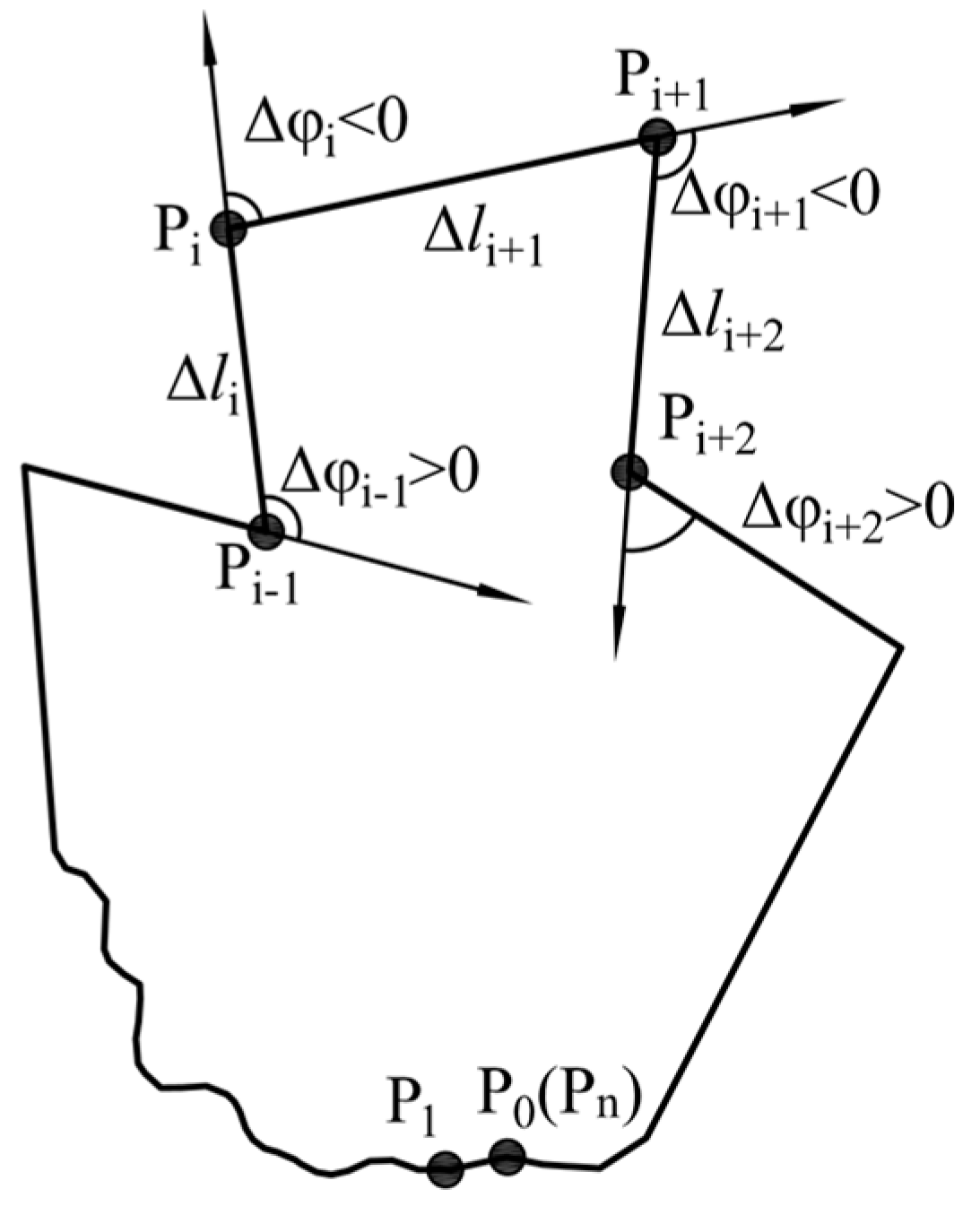
  • Determine the position of the sequential points to be generated. To determine the position of sequential points, a series of angular turns need to be conducted. The common approach to solve this problem is to treat the polygon segments as vectors. The counterclockwise angle that vector P i P i + 1 makes with the positive x-axis is βi. For i=1, βi is a random number varying uniformly between 0 and 2π. For i >1, the value of this angel can be calculated by Equation (6)
    βi = βi−1 + Δφi (i >1)
    where Δφi is the angle bend at point Pi, which is treated as a uniformly distributed random variable. In the procedures of generating randomly shaped polygon, the orientation of the angle should be taken into account and are randomly assigned. For i >1, the coordinates of Pi in a Cartesian coordinate system can be represented by Equation (7)
    { x i = x i 1 + l step × cos ( β i ) y i = y i 1 + l step × sin ( β i ) ( i > 1 )
    where lstep is constant step length.
  • To ensure the points on the polygon are generated counterclockwise, the point Pi should be at the left side of line OPi-1 or on the line (for example, point P5 in Figure 3). This can be validated using the cross product of vector OP i and OP i 1 . The calculation of the cross product is conducted through Equation (3). If this condition is satisfied, proceed with step 4; otherwise, repeat from step 2.
  • Calculate DOPi —the distance between O and the generated point Pi(xi, yi). There are two parameters required to be inputted in advance in this part. They are the minimum distance Dmin and the maximum distance Dmax between the center O and the generated points. If the distance is within the specified range (Dmin ≤ DOPi ≤ Dmax) then the point is stored as a new vertex. Otherwise repeat from step 2.
  • If a point cannot be generated within specified times of trials, then remove the vertex stored in the previous step and repeat from step 2.
  • The summation of all the angular bends from the initial starting point and the point generated in the previous step is φ (φ=∑Δφi). In case of the generation of spiral polygon (a spiral polygon is a simple polygon whose boundary chain contains exactly one concave subchain [38]), φ should equal to 2π [39]. Consequently, repeat steps 2, 3, and 4 until the value of φ is larger than or equal to 2π.
If the value of φ satisfies the convergence criteria in step 6, then delete the last point and connect the stored vertexes counterclockwise. Thus, individual polygon with irregular shape is successfully generated. If necessary, the above steps are repeated until the specified amount of polygon are obtained. It should be noted that the distance between point Pn and P1 may not equal to lstep. However, this situation does not have a significant influence on the polygon contour.

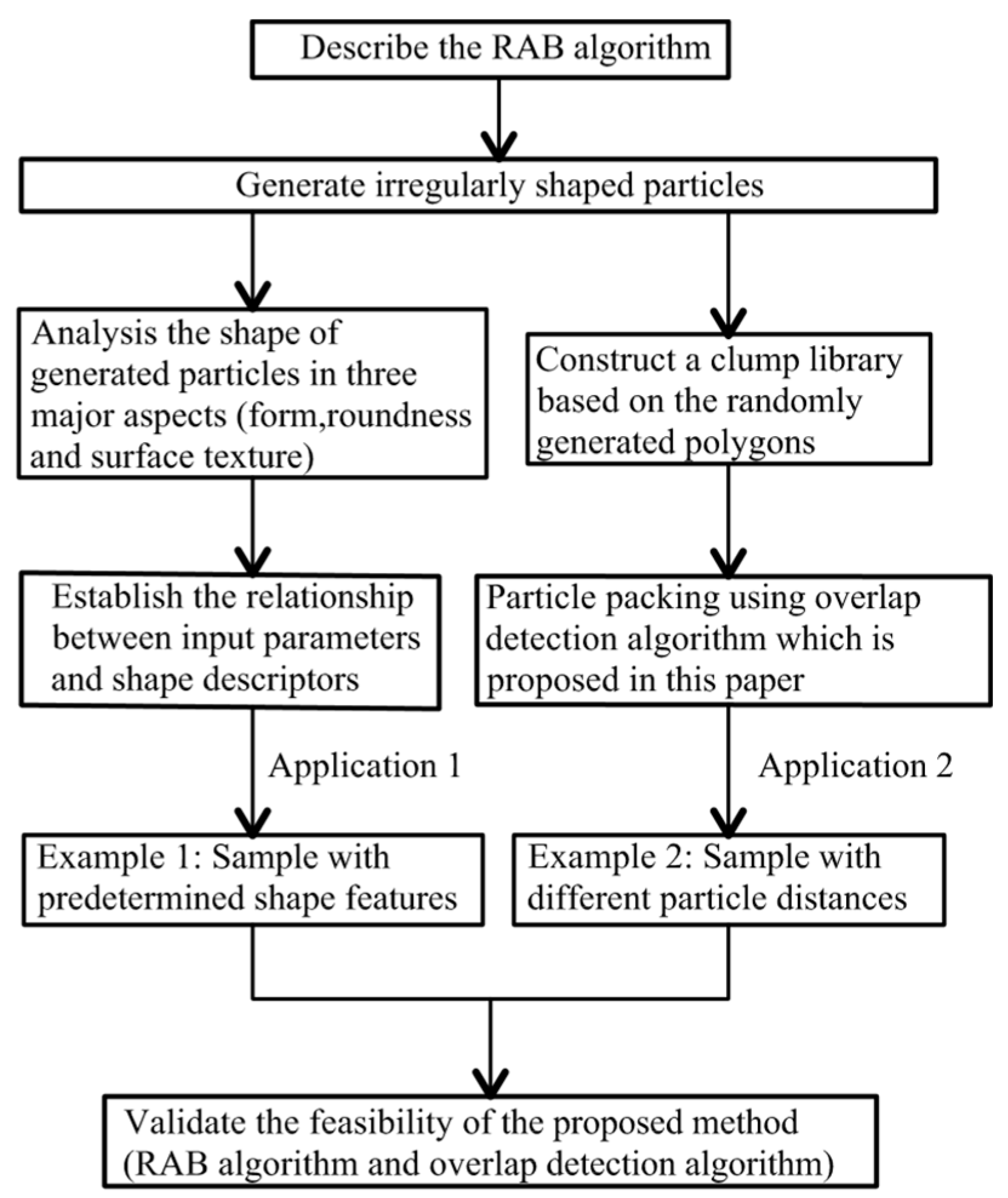
3. Analysis of the Generated Particle Shape

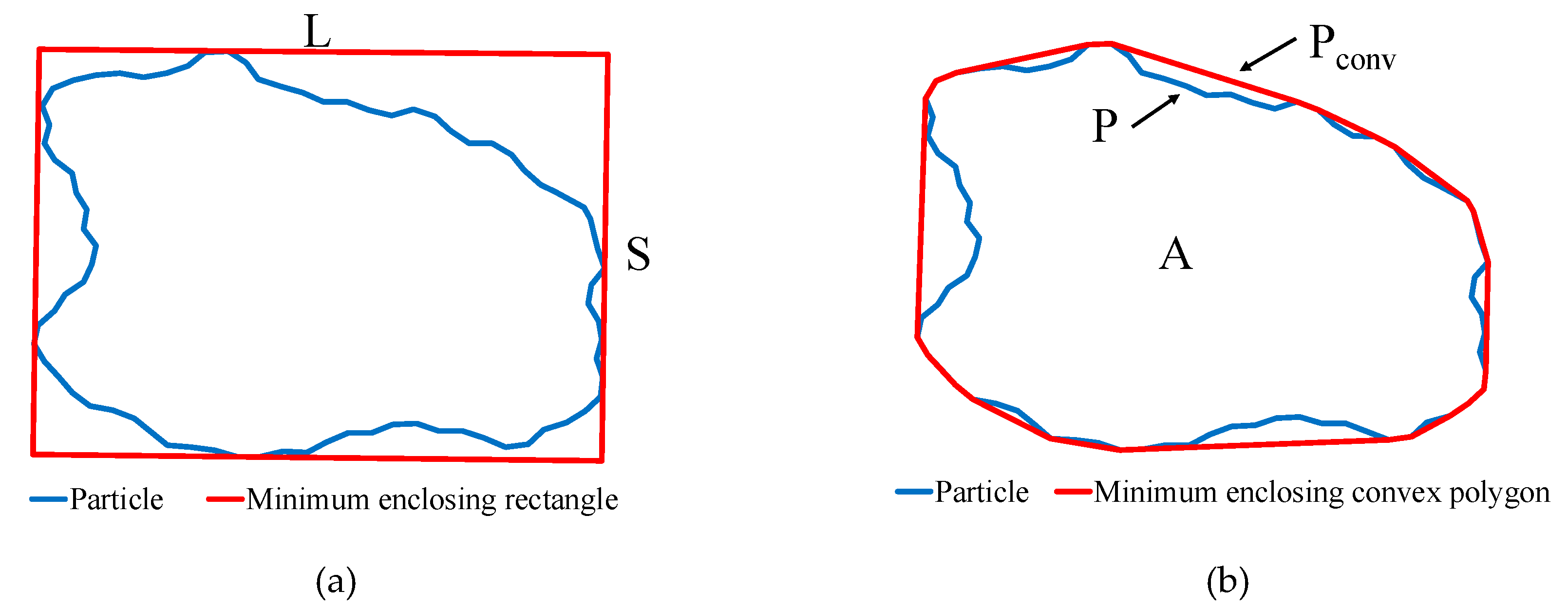
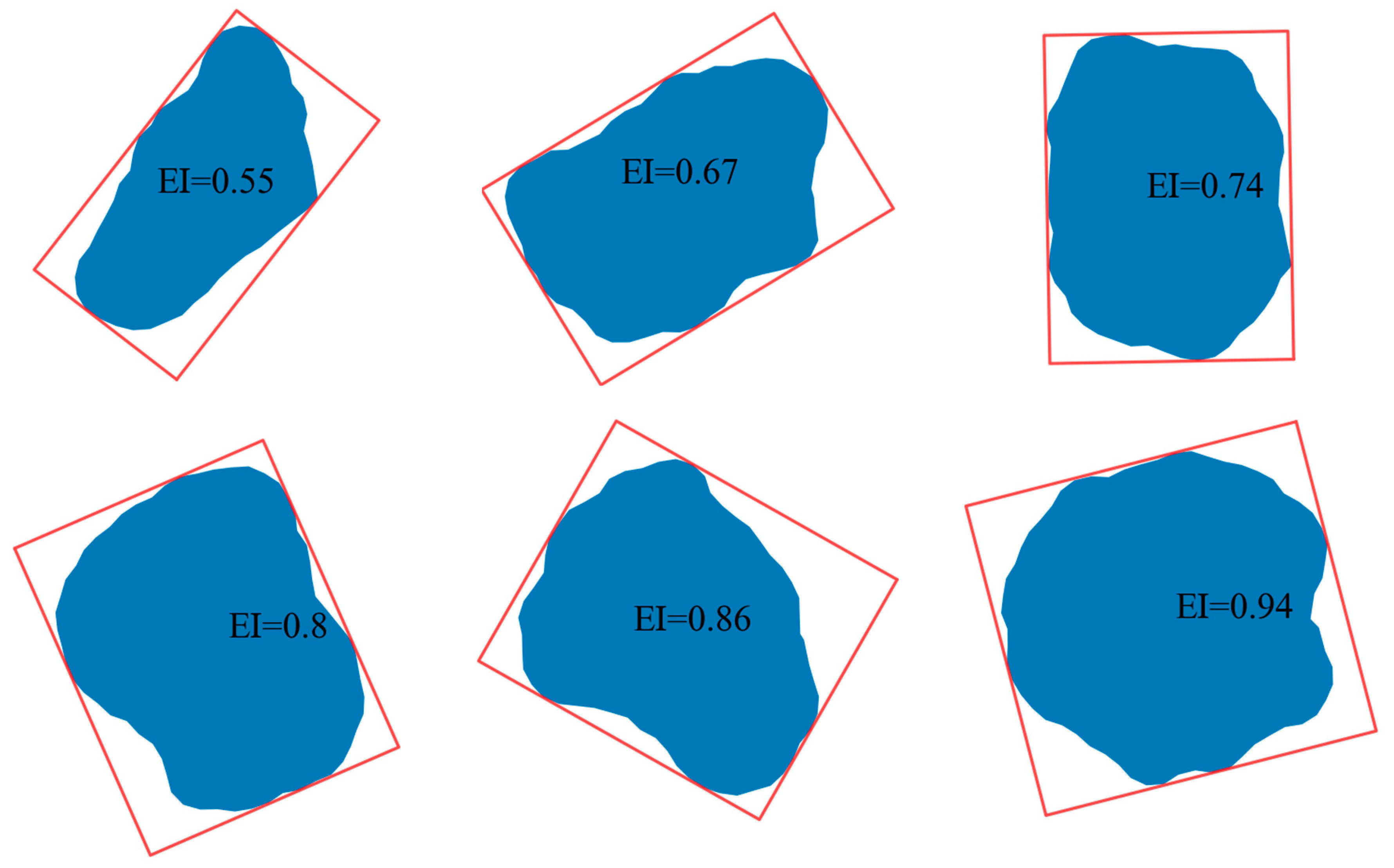
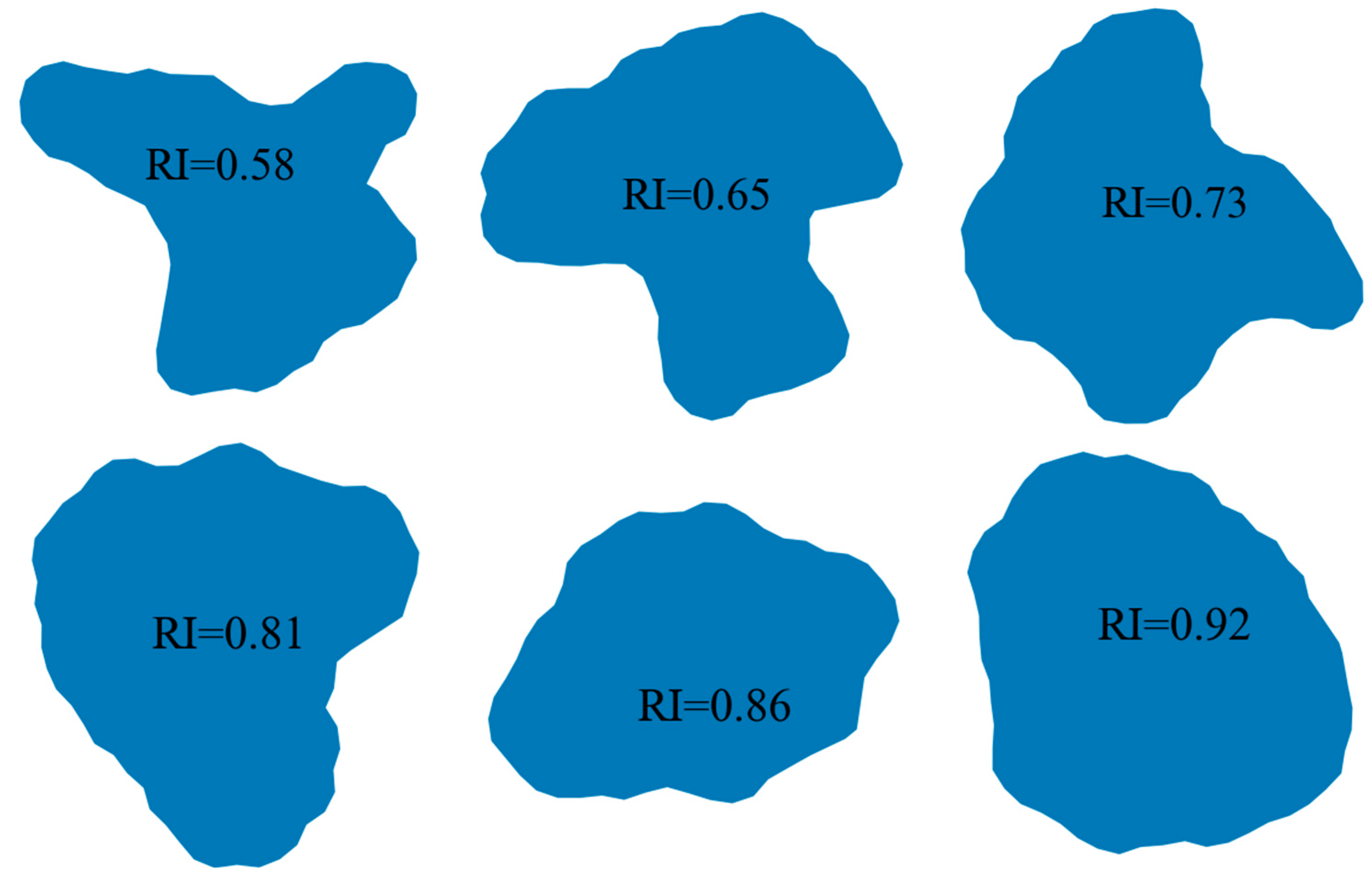
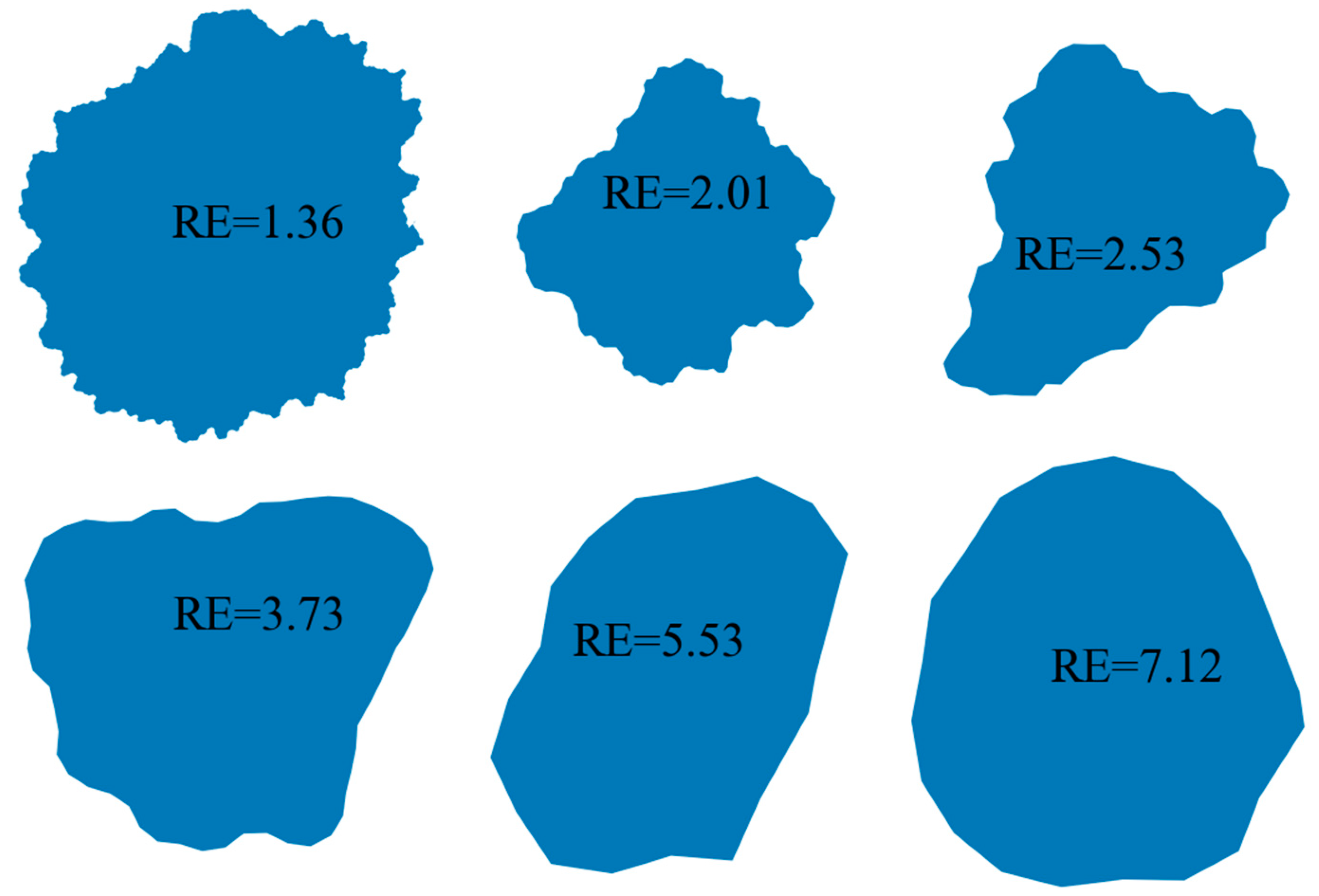
3.1. Shape Descriptors

Many attempts have been made to quantitatively analyze the geometrical characteristics of particles in the literature. Based on the dimensional scales, the morphological characteristics of these particles are expressed in terms of three major aspects: form (overall shape), roundness (angularity), and surface texture (roughness) [26,40,41].
Form, the property of the first level, represents spatial irregularities of particle shape in the large dimension. The common shape include circle, ellipse, rectangle, etc. Shape descriptors, such as elongation index (EI), aspect ratio (AR), and flatness index (FI) are used to quantify the basic shape characteristic of particle. The EI can be determined as follows Equation (8) [22]
EI = S / L
where S and L equal to the width and length of the smallest rectangular box containing the particle, respectively (Figure 4a). The elongation index varies from 0 to 1, where the higher value of EI indicates a lower degree of elongation. For a circle, the EI equals to 1. Particles with different elongation index are shown in Figure 5.
Roundness—the property of the second level—describes the variations of particle shape in the medium dimension, which reflects the average sharpness at corners. It is independent of the overall shape. Available shape descriptors including angularity index, roundness index (RI) and others are of this expression. The degree of roundness is defined and calculated via the following Equation (9) [42].
RI = 4 π A P 2
where A is the projected area and P is the perimeter of the particle contour (see Figure 4b). Figure 6 displays six particles generated using the proposed algorithm. It is obvious that as RI increase from 0.58 to 0.92, high rounded particles can be obtained (Figure 6).
Surface texture, the property of the third level, refers to the surface features which are small-scale relative to the size of the object [41]. Roughness index and regularity index are generally used to describe the surface texture features. The regularity index (RE) is defined as Equation (10) [22]
RE = log ( P P P conv )
where P is the perimeter and Pconv is the convex perimeter of the particle (see Figure 4b). The value of regularity greater than 3 or 4 indicated the particle surface is very smooth. The example particles shown in Figure 7 illustrate this point.
From Figure 5, Figure 6 and Figure 7, it is obvious that three shape descriptors mentioned above—elongation index, roundness index and regularity index—have a good performance in obtaining the multiaspect characteristics of particle shape (form, roundness, and surface texture of a particle outline). So these three shape descriptors are chosen for the quantitative shape analysis in the following section.

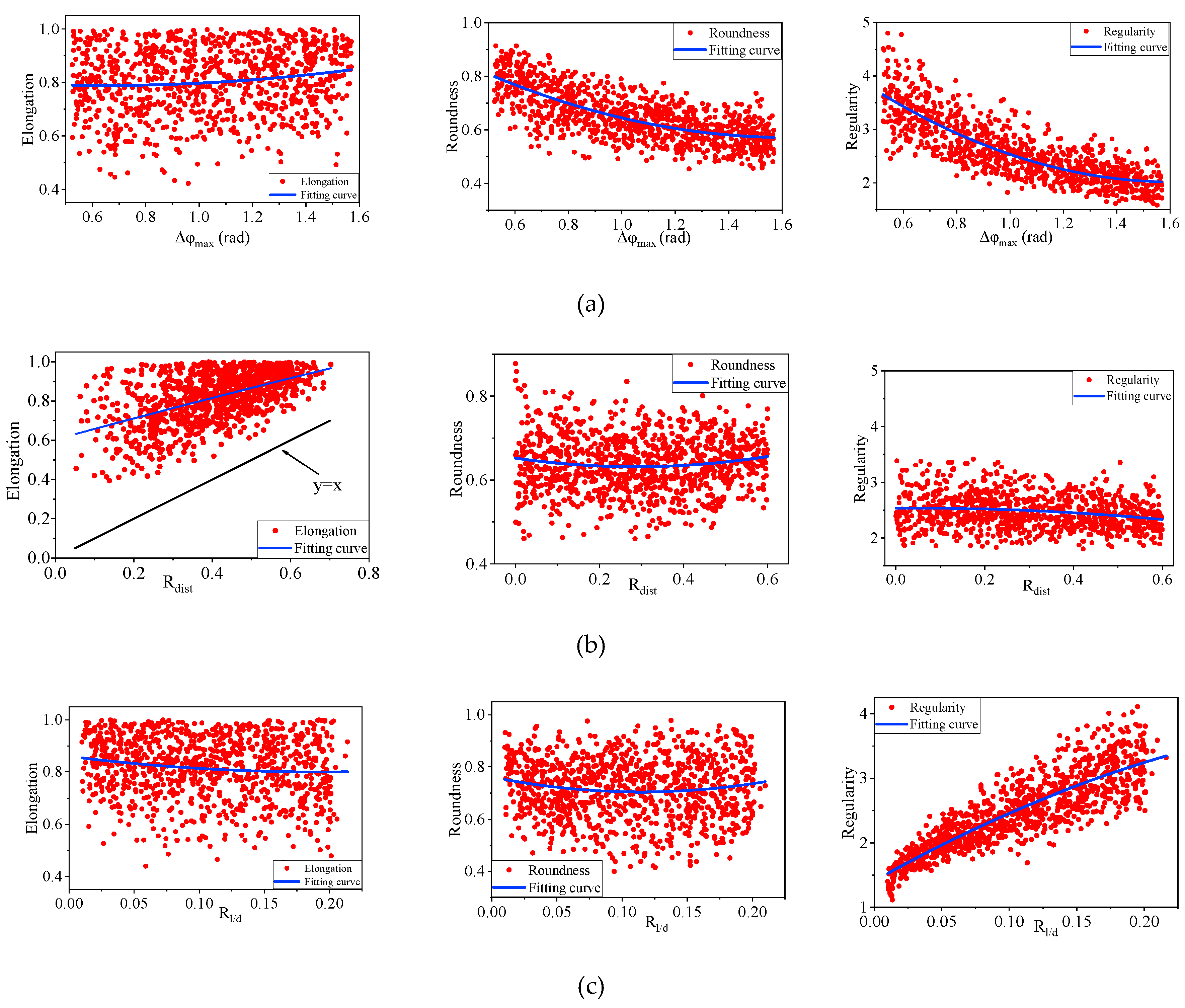
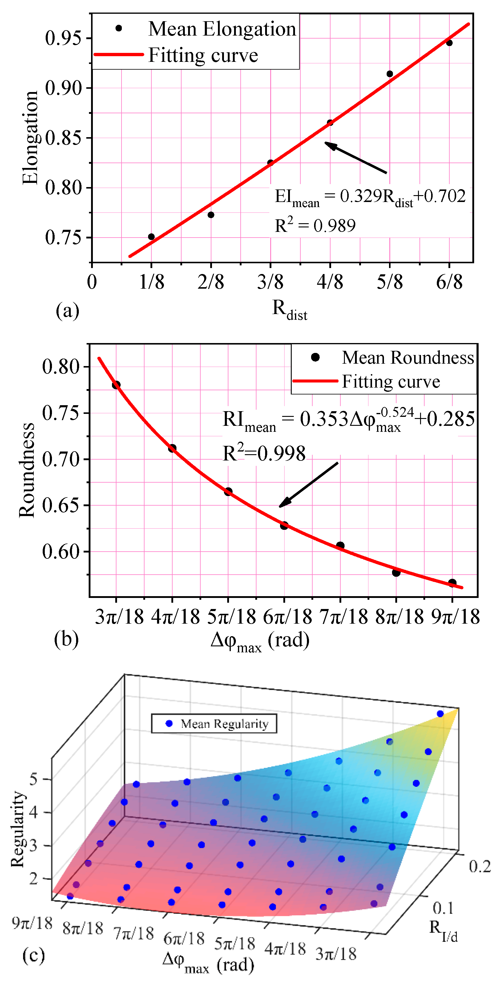
3.2. Relationship between Input Parameters and Shape Descriptors

There are several parameters required to be inputted manually in RAB algorithm. They are the minimum distance Dmin and the maximum distance Dmax between the center O and the generated points, the range of angle bend Δφi and the step length lstep (see Figure 3). In this paper, the minimum value of Δφi is set to 0 and the step length is treated as a constant. To better control the shape of generated particle, based on the geometric relationship between these parameters, these parameters are summarized and classed into three representative parameters, which are Rdist—the ratio between Dmin and Dmax, Rl/d—the ratio between lstep and Dmax and the maximum value of angle bend Δφmax (see Equations (11)–(13)).
Rdist = Dmin / Dmax
Rl/d = lstep / Dmax
Δ φ max Max ( | Δ φ 1 | ,   | Δ φ 2 | , ,   | Δ φ n | )
To explore the influence of these three parameters on shape descriptors (EI, RI and RE), each of them is considered as a random variable, within a specified range. Based on the range of Rdist, Rl/d, Δφmax, which are provided in Table 1, 1000 irregularly shaped polygons are generated for each group. The values of shape descriptors are obtained using Equations (8)–(10), respectively. Figure 8 presents the effect of the three representative parameters on particle shape. The influence can be determined through the dispersion degree of the data points, which is obtained by range analysis. The greater dispersion degree indicates the input parameter has marginal control effect on corresponding shape descriptors. By comparison of the graphs in the same column, combined with the dispersion degree of data point, the effect of three representative parameters on shape descriptors are investigated through qualitative analysis. Besides, some fitting curves are almost horizontal in Figure 8, indicating that the control effect of corresponding parameters on a certain shape descriptors is rather limited or can be neglected.
Figure 8a illustrates the influence of parameters Δφmax on the generated particle shapes. It is obvious that Δφmax is well correlated with the particle roundness and regularity. Nevertheless, an increase of Δφmax has limited effect on the particle elongation. However, with the increase of Rdist, the variation of shape descriptors is different with the above situation (see Figure 8b). Based on the results of shape analysis, the EI of generated shape is almost always greater than that of corresponding Rdist. Thus, in the process of generating random particles, Rdist can be used to control the minimum value of elongation, while Rdist has limited influence on RI and RE. Finally, the discrete degree of the data points shown in Figure 8c reflects the influence of Rl/d. It can be observed that this parameter have negligible influences on elongation and roundness. Nevertheless, increase of Rl/d leads to a significant increase of particle regularity.
Based on the analysis above, the three shape descriptors are controlled by single or multiple input parameters with an obvious effect. The relationship between input parameter and shape descriptor is obtained by using the curve fitting method (Figure 9). The correlation coefficient R2 is adapted to evaluate fitting precision [43,44]. Among these shape descriptors, the minimum and mean value of elongation (EImin and EImean ) are determined by Rdist (Figure 9a), which can be expressed as
EImin ≧ Rdist
EImean = 0.329Rdist + 0.702
Besides, as shown in Figure 9b, the Δφmax has a statistically significant relationship with the mean value of roundness (RImean). The value is calculated based on the following fitting formula.
RImean = 0.353Δφmax−0.524 + 0.285
Different from EI and RI, the mean value of regularity (REmean) is controlled by both Δφmax and Rl/d (Figure 9c). The predictive formula could be obtained by the curve fitting method with R2 =0.989 and expressed as follows
REmean = 3.43 + 23.99Rl/d − 3.578Δφmax − 6.985 R2l/d − 11.57 Rl/d · Δφmax + 1.504Δφ2max
Thus, in the procedure of generating random particles, the shape of particles can be quantitatively controlled based on Equations (14)–(17).

4. Overlap Detection Algorithm

After a series of arbitrarily shaped polygons are introduced, the generated geometric models are import into the Particle Flow Code PFC2D (Version 5.0., Itasca Consulting Group Inc.: Minneapolis, MN, USA) [33] to construct clump library. PFC2D is a two-dimensional DEM software. The particles are treated as disks or clumps, and can both translate and rotate. The movement of particle obeys Newton’s laws of motion. Based on the mid-surface method, the clumps are created to represent realistic particle shapes [34] and appropriately packed in the model domain. To facilitate random and quick allocation of irregularly shaped clumps, an overlap detection algorithm is proposed in this section. This algorithm can be summarized as follows.
  • Construct a clump library based on the randomly generated polygons.
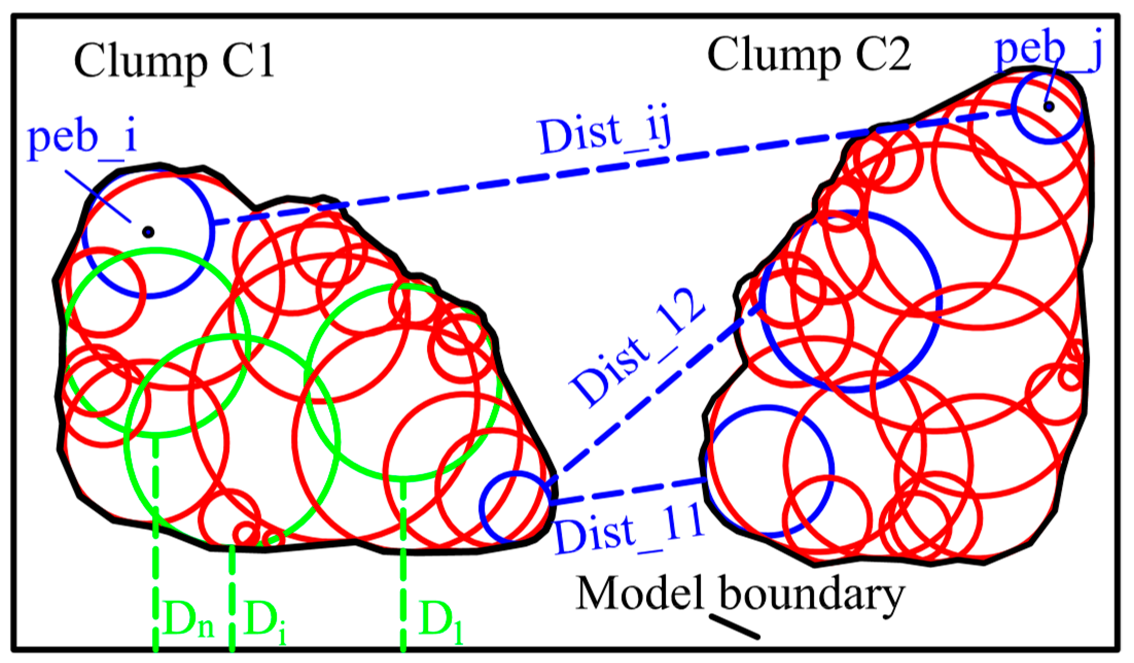
  • Select a clump from the library and specify the position randomly in the model domain. It is obvious that the shape of a clump is determined by the position and radii of the comprising pebbles. Based on the pebble information, the minimum distance between the clump and the boundary of model can be determined by calculating the distance (Di) between each pebble and the model boundary (see Figure 10).
  • Detect overlap between the clump and model boundary. If the minimum distance between them is greater than or equal to zero, it suggest that the clump does not intersect with the boundaries of model. If this condition is satisfied, store the clump information; otherwise, repeat from step 2.
  • Put next clump in the model domain and calculate the minimum distance between this clump and the packed clumps (or the model boundary) based on the position and radii of all the pebbles. If this clump do not overlap with the packed clumps or exceed the model boundary, store the clump and pebble information; otherwise, repeat this step.
  • Repeat step 4 until a given condition is satisfied (e.g., the number of all the clumps, the area of all the clumps).
The most important part of the algorithm is the calculation of the minimum distance between clumps or the distance between clump and the model boundary. This is an iterative procedure in which the minimum distance is determined by calculating the distance between pebbles in new selected clump and pebbles in the packed clumps (and the distance between pebbles in new selected clump and model boundary). As shown in Figure 10, the distance between clumps C1 and C2 is defined by Equation (18):
Dist(C1,C2) = Minimum(Dist_11, Dist_12, Dist_13…, Dist_ij)
where Dist_ij is the distance between pebble peb_i in clump C1 and pebble peb_j in C2. In a similar way, the distance between clump and model boundary can be calculated. Thus, in the procedures of clump packing, the distance between each clumps in the model domain can be precisely controlled.

5. Application of Proposed Algorithm

To validate the feasibility of the proposed RAB and overlap detection algorithms in modeling of granular materials, two group of granular mixture samples for application examples are generated in the following sections.

5.1. Modeling of Granular Mixture Materials

Granular mixtures are inhomogeneous multiphase materials, which are consisted of coarse particles and fine particles [45]. In this numerical model, the coarse particles are simulated using clumps of overlap pebbles and fine particles by single disk. The procedures of modeling granular mixture are as follows (Figure 11).
  • Code the RAB algorithm in Python and input parameters Rdist, Rl/d, and Δφmax to simulate the geometric model of individual coarse particle with irregular shape.
  • Import the generated geometric model into PFC2D to construct clump library. The clumps are created based on mid-surface method. These clumps are used to represent realistic coarse particle.
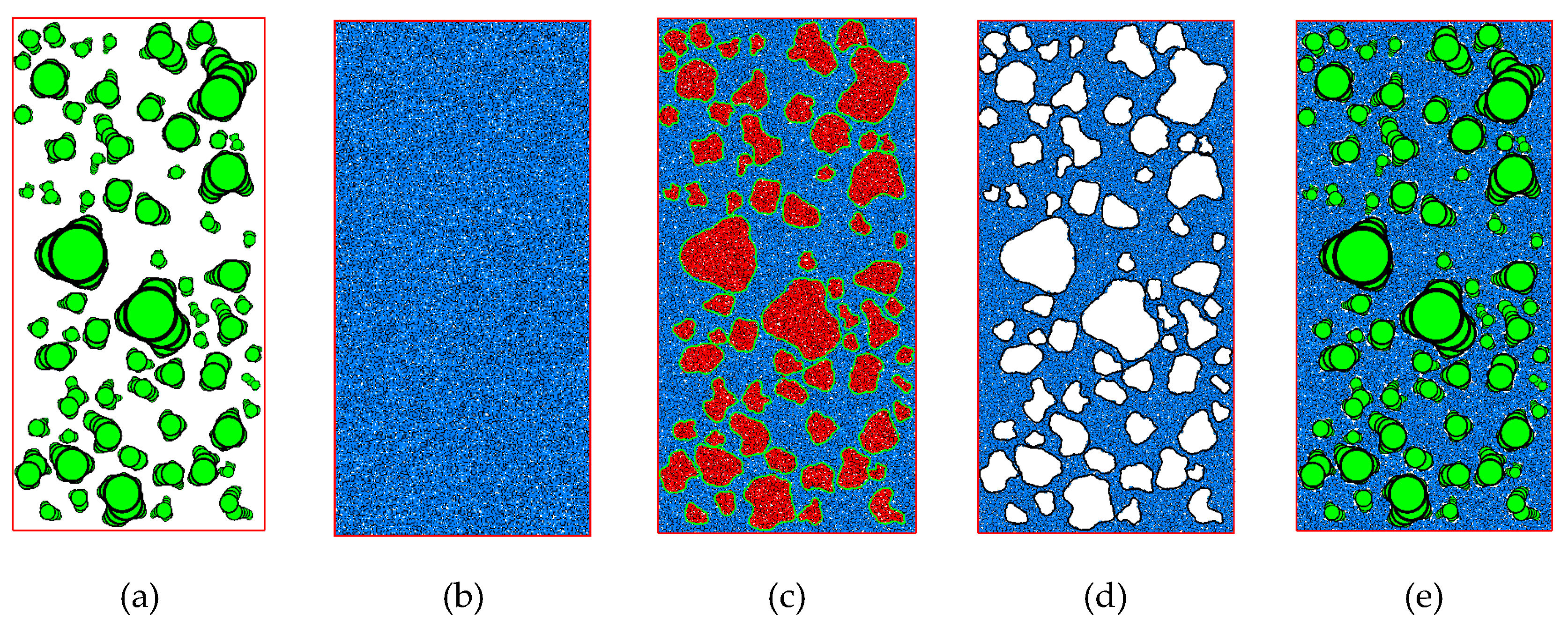
  • Put coarse particles into the model domain based on the overlap detection algorithm which is proposed above (Figure 11a).
  • Generate sample that is composed of single disk to simulate fine particles in the same model domain (Figure 11b). The size of particle and the porosity of fine particles specimen should be in a given range.
  • Remove fine particles that overlap with coarse particles (Figure 11c,d). The generated granular mixture sample is shown in Figure 11e.

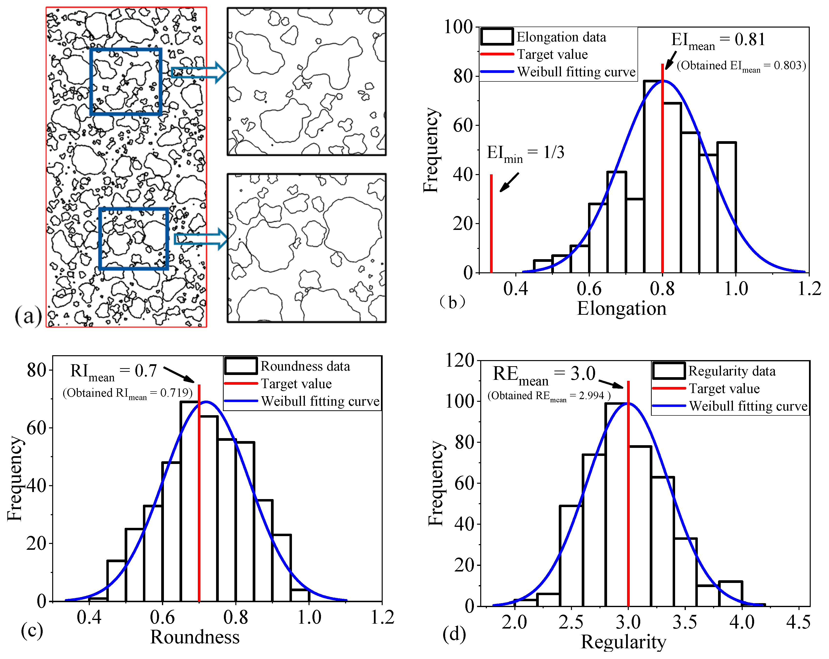
5.2. Granular Mixture with Predetermined Coarse Particle Shape Features

The relationship between input parameters (Rdist, Rl/d, and Δφmax) and shape descriptors are discussed in Section 3.2, as well as the input parameters used to control particle shape features (such as the mean value of some shape descriptors). This section illustrates the capabilities of the proposed method in generating sample with predetermined shape feature. In this example, the mean and minimum elongation are equal to 0.81 and 1/3, respectively. The value of mean roundness (RImean) and mean regularity (REmean) are set to 0.7 and 3.0, respectively. Based on Equations (14)–(17), the three representative parameters (Rdist, Rl/d, and Δφmax) are back-calculated. The values are 1/3, 0.094, and 0.735, respectively. Besides, the equivalent diameters of the coarse particles varied uniformly from 0.01 to 1.0 cm and the coarse particles content is specified as 40%. It should be noted that because the clumps are used to represent realistic coarse particles shapes. Therefore, the area of all the coarse particles is obtained by calculating the area of clumps not that of randomly generated polygons. A granular mixture sample with predetermined shape feature and the derived distributions of the three shape descriptors (elongation, roundness, and regularity) are shown in Figure 12. It can be observed that the shape descriptors have a good match with the target value, which validates the feasibility of the RAB algorithm and three representative parameters in precisely controlling the generation of granular materials.

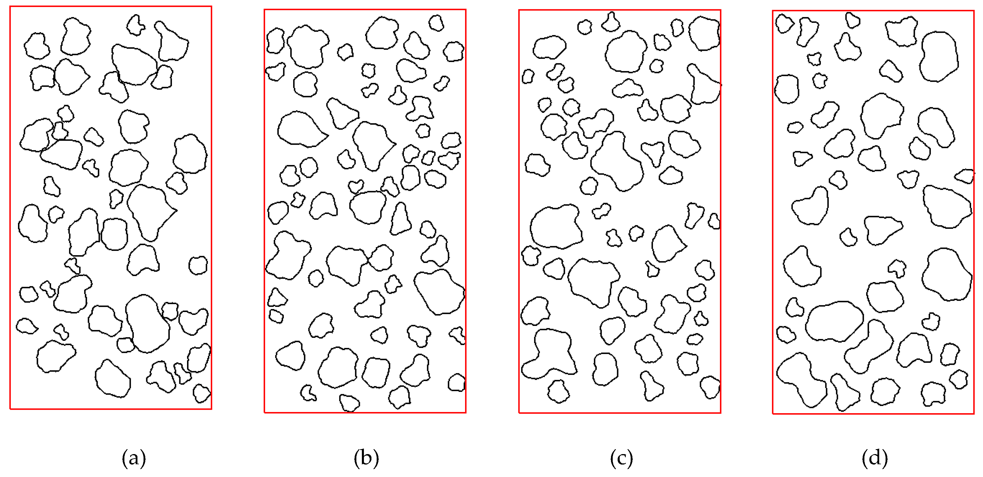
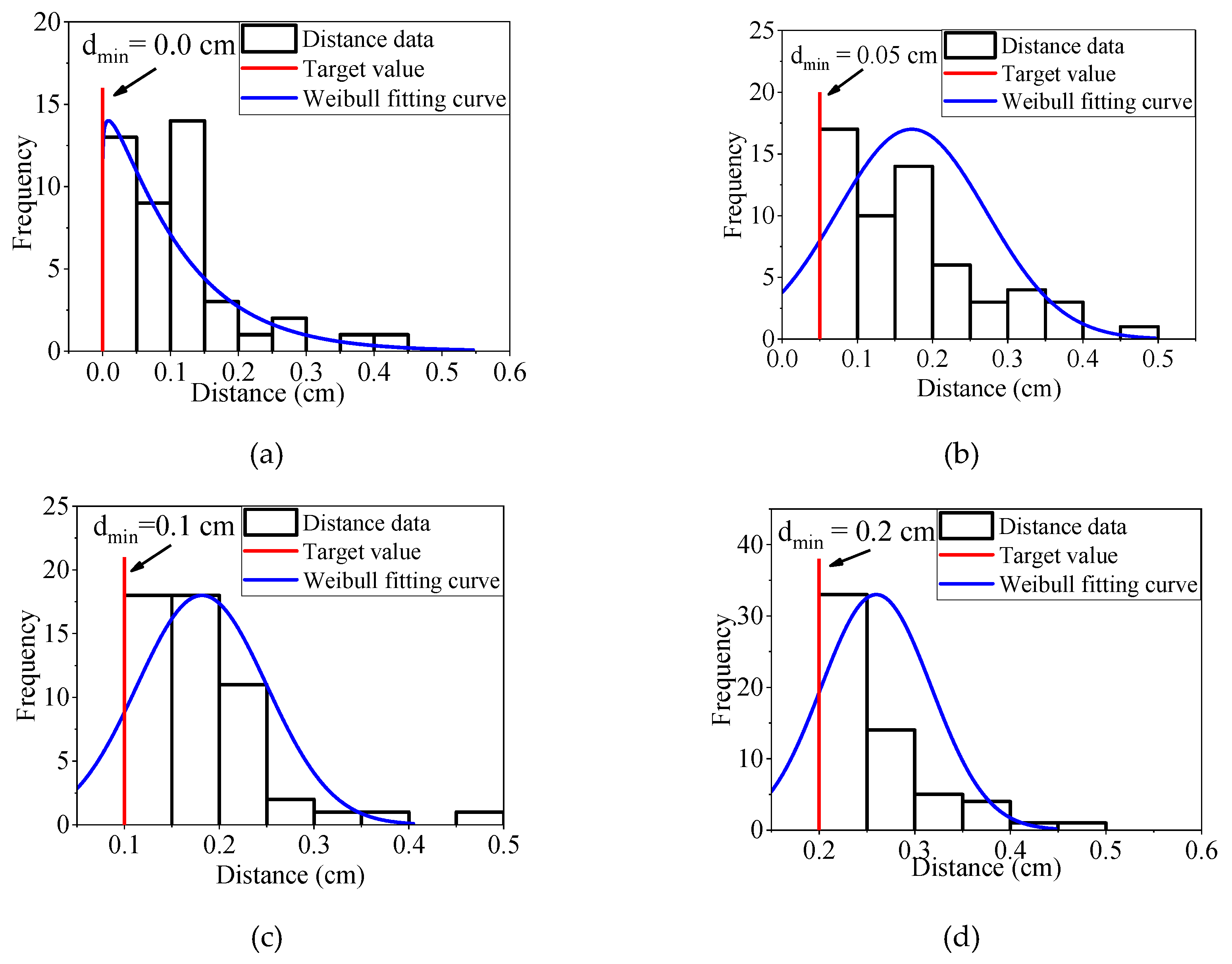
5.3. Granular Mixture with Different Coarse Particle Distances

The proposed overlap detection algorithm has an advantage in calculation of the minimum distance between coarse particles or the distance between coarse particle and the model boundary. To illustrate the capability of this algorithm, four granular mixture samples with different minimum coarse particle distances are generated (Figure 13). For these four samples, the minimum distance (dmin) between coarse particles are 0, 0.05, 0.10, and 0.20 cm, respectively. The values of Δφmax, Rdist, and Rl/d are set to π/4, 1/3, and 0.1, respectively. The value range of equivalent diameters are 0.3 to 1.5 cm. The content of the coarse particles is equal to 30%. The distributions of minimum distance between clumps are shown in Figure 14. All these results show that distance meet the requirements of the target value.

6. Conclusions

This paper presents a systematic method to generate arbitrary two-dimensional particle for the numerical simulation of granular materials. A random angular bend (RAB) algorithm is proposed and coded in Python to simulate the geometric model of individual particle with irregular shape. Three representative parameters (Rdist, Rl/d, and Δφmax) are used to quantitatively control the shape feature of generated polygons in terms of three major aspects (form, roundness, and surface texture). Besides, a novel overlap detection algorithm is developed to address difficulties associated with spatial allocation of irregularly shaped particles. Finally, two examples are further employed to validate the feasibility of the proposed algorithm for the numerical modeling of realistic granular materials. The main conclusions are summarized as follows.
  • The proposed RAB algorithm shows a good performance in the generation of randomly shaped polygons (especially for nonstar-like particle reconstruction based on image information).
  • Three representative parameters (Rdist, Rl/d, and Δφmax) in RAB algorithm could quantitatively control the shape feature of generated polygons by control three shape descriptors (elongation index, roundness index, and regularity). Besides, these three parameters have definitude physical meaning, which makes the RAB algorithm easier to understand.
  • The proposed overlap detection algorithm is able to allocate particle to the model domain easily by calculating the minimum distance between coarse particles or the distance between coarse particle and the model boundary.
It should be noted that the RAB algorithm is only suitable for the generation of two-dimensional particle. For real 3D particle modeling, this algorithm needs to be extended to a general 3D case in future works. The study provide a foundation for the construction of granular materials based on angular bend theory.

Author Contributions

Conceptualization, Z.W.; Data curation, W.Z.; Funding acquisition, W.Z.; Writing—original draft, Z.W.; Writing—review & editing, W.Z. and L.W.

Funding

This research was funded by Natural Science Foundation of Chongqing, China (cstc2018jcyjAX0632), and the Chongqing Engineering Research Center of Disaster Prevention & Control for Banks and Structures in the Three Gorges Reservoir Area (Nos. SXAPGC18ZD01).

Conflicts of Interest

The authors declare no conflicts of interest.

List of symbols

lArc length from point P0 up to the vertex Pi
φCumulative angular bends
PiThe ith vertex on the polygon
ΔliEdge length
ΔφiAngular bend at vertex Pi
LallThe total length of the polygon.
βiThe counterclockwise angle that vector P i P i + 1 makes with the positive x-axis
lstepConstant step length
EIElongation index
SThe width of the smallest rectangular box containing the particle
LThe length of the smallest rectangular box containing the particle
RIRoundness index
AThe projected area of the particle
PThe perimeter of the particle
RERegularity index
PconvThe convex perimeter of the particle
DOPiThe distance between O and the generated point Pi
DminThe minimum distance between the center O and the generated points
DmaxThe maximum distance between the center O and the generated points
RdistThe ratio between Dmin and Dmax
Rl/dThe ratio between lsteplength and Dmax
ΔφmaxThe maximum value of angle bend
EIminThe minimum value of elongation
EImeanThe mean value of elongation
RImeanThe mean value of roundness
REmeanThe mean value of regularity
DiThe distance between pebble and the model boundary
Dist_ijThe distance between pebble peb_i in clump C1 and pebble peb_j in C2
dminThe minimum distance between coarse particles

References

  1. Weinhart, T.; Thornton, A.R.; Einav, I. Editorial: Modelling and computational challenges in granular materials. Comput. Part. Mech. 2016, 3, 291–292. [Google Scholar] [CrossRef]
  2. Sinnott, M.D.; Cleary, P.W. The effect of particle shape on mixing in a high shear mixer. Comput. Part. Mech. 2016, 3, 477–504. [Google Scholar] [CrossRef]
  3. Bayesteh, H.; Ghasempour, T. Role of the location and size of soluble particles in the mechanical behavior of collapsible granular soil: A DEM simulation. Comput. Part. Mech. 2018. [Google Scholar] [CrossRef]
  4. Cundall, P.A. A computer model for simulating progressive, large-scale movement in blocky rock system. In Proceedings of the International Symposium on Rock Mechanics, Nancy, France, 4–6 october 1971. [Google Scholar]
  5. Cundall, P.A.; Strack, O.D. A discrete numerical model for granular assemblies. Geotechnique 1979, 29, 47–65. [Google Scholar] [CrossRef]
  6. Kun, F.; Herrmann, H.J. A study of fragmentation processes using a discrete element method. Comput. Method. Appl. Mech. Eng. 1996, 138, 3–18. [Google Scholar] [CrossRef] [Green Version]
  7. Cho, N.; Martin, C.D.; Sego, D.C. A clumped particle model for rock. Int. J. Rock Mech. Min. Sci. 2007, 44, 997–1010. [Google Scholar] [CrossRef]
  8. Suchorzewski, J.; Tejchman, J.; Nitka, M. Discrete element method simulations of fracture in concrete under uniaxial compression based on its real internal structure. Int. J. Damage Mech. 2018, 27, 578–607. [Google Scholar] [CrossRef]
  9. Bandeira, A.A.; Zohdi, T.I. 3D numerical simulations of granular materials using DEM models considering rolling phenomena. Comput. Part. Mech. 2019, 6, 97–131. [Google Scholar] [CrossRef]
  10. Rong, G.; Liu, G.; Hou, D.; Zhou, C.b. Effect of particle shape on mechanical behaviors of rocks: A numerical study using clumped particle model. Sci. World J. 2013, 2013. [Google Scholar] [CrossRef]
  11. Santamarina, J.; Cho, G.C. Soil behaviour: The role of particle shape. In Proceedings of the Advances in Geotechnical Engineering: The Skempton Conference, London, UK, 29–31 March 2004; pp. 604–617. [Google Scholar]
  12. Guan, Y.; Liu, X.; Wang, E.; Wang, S. The Stability Analysis Method of the Cohesive Granular Slope on the Basis of Graph Theory. Materials 2017, 10, 240. [Google Scholar] [CrossRef]
  13. Miao, Y.H.; Yu, W.X.; Hou, Y.; Guo, L.Y.; Wang, L.B. Investigating the Functions of Particles in Packed Aggregate Blend using a Discrete Element Method. Materials 2019, 12, 556. [Google Scholar] [CrossRef] [PubMed]
  14. Ting, J.M.; Meachum, L.; Rowell, J.D. Effect Of Particle-Shape on the Strength And Deformation Mechanisms Of Ellipse-Shaped Granular Assemblages. Eng. Comput. 1995, 12, 99–108. [Google Scholar] [CrossRef]
  15. Ting, J.M.; Khwaja, M.; Meachum, L.R.; Rowell, J.D. An Ellipse-Based Discrete Element Model for Granular-Materials. Int. J. Numer. Anal. Method. Geomech. 1993, 17, 603–623. [Google Scholar] [CrossRef]
  16. Timofeeva, E.V.; Routbort, J.L.; Singh, D. Particle shape effects on thermophysical properties of alumina nanofluids. J. Appl. Phys. 2009, 106. [Google Scholar] [CrossRef]
  17. Chen, W.; Donohue, T.; Katterfeld, A.; Williams, K. Comparative discrete element modelling of a vibratory sieving process with spherical and rounded polyhedron particles. Granul. Matter 2017, 19, 81. [Google Scholar] [CrossRef]
  18. Wang, J.; Yu, H.S.; Langston, P.; Fraige, F. Particle shape effects in discrete element modelling of cohesive angular particles. Granul. Matter 2011, 13, 1–12. [Google Scholar] [CrossRef]
  19. Li, T.; Peng, Y.; Zhu, Z.; Zou, S.; Yin, Z. Discrete Element Method Simulations of the Inter-Particle Contact Parameters for the Mono-Sized Iron Ore Particles. Materials 2017, 10, 520. [Google Scholar] [CrossRef] [PubMed]
  20. Wang, Z.M.; Kwan, A.K.H.; Chan, H.C. Mesoscopic study of concrete I: Generation of random aggregate structure and finite element mesh. Comput. Struct. 1999, 70, 533–544. [Google Scholar] [CrossRef]
  21. Liu, Q.; Jiang, Y.; Wu, Z.; He, J. A Voronoi element based-numerical manifold method (VE-NMM) for investigating micro/macro-mechanical properties of intact rocks. Eng. Fract. Mech. 2018, 199, 71–85. [Google Scholar] [CrossRef]
  22. Mollon, G.; Zhao, J. Fourier–Voronoi-based generation of realistic samples for discrete modelling of granular materials. Granul. Matter 2012, 14, 621–638. [Google Scholar] [CrossRef]
  23. Shan, P.; Lai, X. Mesoscopic structure PFC∼ 2D model of soil rock mixture based on digital image. J. Vis. Commun. Image Represent. 2019, 58, 407–415. [Google Scholar] [CrossRef]
  24. Zheng, J.; Hryciw, R.D. An image based clump library for DEM simulations. Granul. Matter 2017, 19, 26. [Google Scholar] [CrossRef]
  25. Zheng, J.; Hryciw, R.D. A corner preserving algorithm for realistic DEM soil particle generation. Granul. Matter 2016, 18, 84. [Google Scholar] [CrossRef]
  26. Zhao, L.; Huang, D.; Dan, H.C.; Zhang, S.; Li, D. Reconstruction of granular railway ballast based on inverse discrete Fourier transform method. Granul. Matter 2017, 19, 74. [Google Scholar] [CrossRef]
  27. Wang, X.; Liang, Z.; Nie, Z.; Gong, J. Stochastic numerical model of stone-based materials with realistic stone-inclusion features. Constr. Build. Mater. 2018, 197, 830–848. [Google Scholar] [CrossRef]
  28. Nie, Z.; Zhu, Y.; Wang, X.; Gong, J. Investigating the effects of Fourier-based particle shape on the shear behaviors of rockfill material via DEM. Granul. Matter 2019, 21, 22. [Google Scholar] [CrossRef]
  29. Bowman, E.T.; Soga, K.; Drummond, W. Particle shape characterisation using Fourier descriptor analysis. Géotechnique 2001, 51, 545–554. [Google Scholar] [CrossRef]
  30. Su, D.; Yan, W.M. Quantification of angularity of general-shape particles by using Fourier series and a gradient-based approach. Constr. Build. Mater. 2018, 161, 547–554. [Google Scholar] [CrossRef]
  31. Zahn, C.T.; Roskies, R.Z. Fourier descriptors for plane closed curves. IEEE Trans. Comput. 1972, 100, 269–281. [Google Scholar] [CrossRef]
  32. Python. Python Programming Language. 2018. Available online: https://www.python.org/ (accessed on 10 May 2018).
  33. Itasca, PFC Documentation, Release 5.0; Itasca Consulting Group Inc.: Minneapolis, MN, USA, 2014.
  34. Taghavi, R. Automatic clump generation based on mid-surface. In Proceedings of the 2nd International FLAC/DEM Symposium, Melbourne, Australia, 14–16 February 2011; pp. 791–797. [Google Scholar]
  35. Hundal, H.S.; Rohani, S.; Wood, H.C.; Pons, M.N. Particle shape characterization using image analysis and neural networks. Powder Technol. 1996, 91, 217–227. [Google Scholar] [CrossRef]
  36. Cormen, T.H.; Leiserson, C.E.; Rivest, R.L.; Stein, C. Introduction to Algorithms; MIT press: Cambridge, MA, USA, 2009. [Google Scholar]
  37. MacLeod, N. Generalizing and extending the eigenshape method of shape space visualization and analysis. Paleobiology 1999, 25, 107–138. [Google Scholar]
  38. Everett, H.; Corneil, D.G. Recognizing Visibility Graphs of Spiral Polygons. J. Algorithm. 1990, 11, 1–26. [Google Scholar] [CrossRef]
  39. Bernard-Michel, B.; Rohani, S.; Pons, M.N.; Vivier, H.; Hundal, H.S. Classification of crystal shape using Fourier descriptors and mathematical morphology. Part. Part. Syst. Charact. 1997, 14, 193–200. [Google Scholar] [CrossRef]
  40. Wang, L.; Wang, X.; Mohammad, L.; Abadie, C. Unified method to quantify aggregate shape angularity and texture using Fourier analysis. J. Mater. Civi. Eng. 2005, 17, 498–504. [Google Scholar] [CrossRef]
  41. Blott, S.J.; Pye, K. Particle shape: A review and new methods of characterization and classification. Sedimentology 2008, 55, 31–63. [Google Scholar] [CrossRef]
  42. Janoo, V. Quantification of Shape, Angularity, and Surface Texture of Base Course Materials; Cold Regions Research and Engineering Lab: Hanover, NH, USA, 1998. [Google Scholar]
  43. Zhang, W.G.; Goh, A.T.C. Multivariate adaptive regression splines for analysis of geotechnical engineering systems. Comput. Geotech. 2013, 48, 82–95. [Google Scholar] [CrossRef]
  44. Zhang, W.; Goh, A.T.C. Multivariate adaptive regression splines and neural network models for prediction of pile drivability. Geosci. Front. 2016, 7, 45–52. [Google Scholar] [CrossRef] [Green Version]
  45. Zhou, W.; Wu, W.; Ma, G.; Ng, T.T.; Chang, X.L. Undrained behavior of binary granular mixtures with different fines contents. Powder Technol. 2018, 340, 139–153. [Google Scholar] [CrossRef]
Figure 1. Flowchart of this paper.
Materials 12 02169 g001
Figure 2. Description of Particle shape using the result of the Z-R shape function.
Materials 12 02169 g002
Figure 3. Procedures of generating randomly shaped polygon.
Materials 12 02169 g003
Figure 4. Schematic diagram of shape descriptors: EI, RI, and RE: (a) Diagram of the EI; (b) Diagram of the RI and RE.
Materials 12 02169 g004
Figure 5. Particles with different elongation index.
Materials 12 02169 g005
Figure 6. Particles with different roundness.
Materials 12 02169 g006
Figure 7. Particles with different regularity.
Materials 12 02169 g007
Figure 8. Influence of input parameters on shape descriptor: (a) Influence of Δφmax on particle shape; (b) Influence of Rdist on particle shape; (c) Influence of Rl/d on particle shape.
Materials 12 02169 g008
Figure 9. Relationship between input parameters and shape descriptor: (a) Relationship between input parameters and EImean, (b) relationship between input parameters and RImean, and (c) relationship between input parameters and REmean.
Materials 12 02169 g009
Figure 10. Schematic diagram of distance calculation method.
Materials 12 02169 g010
Figure 11. Procedures of generating granular mixtures: (a) Put coarse particles into the model domain, (b) generate fine particles, (c) overlap detection (the red regions), (d) delete fine particles in the red regions, and (e) generate granular mixtures.
Materials 12 02169 g011
Figure 12. Granular mixture with predetermined coarse particle shape features: (a) Sample of generated granular mixture, (b) elongation distributions of coarse particles, (c) roundness distributions of coarse particles, and (d) regularity distributions of coarse particles.
Materials 12 02169 g012
Figure 13. Granular mixture samples with different minimum coarse particle distances (cm): (a) dmin = 0.0 cm; (b) dmin = 0.05 cm; (c) dmin = 0.10 cm; (d) dmin = 0.20 cm.
Materials 12 02169 g013
Figure 14. Frequency histograms of minimum distance between coarse particles: (a) dmin = 0.0 cm; (b) dmin = 0.05 cm; (c) dmin = 0.10 cm; (d) dmin = 0.20 cm.
Materials 12 02169 g014
Table 1. Ranges of input parameters.
GroupNumber of ParticlesΔφmax (rad)RdistRl/d
Group 11000[π/6, π/2]1/31/10
Group 21000π/3[0,3/5]1/10
Group 31000π/31/3[0.01, 0.2]

