Evaluation of Calcium Carbonate Inhibitors Using Sintered Metal Filter in a Pressurized Dynamic System


Abstract
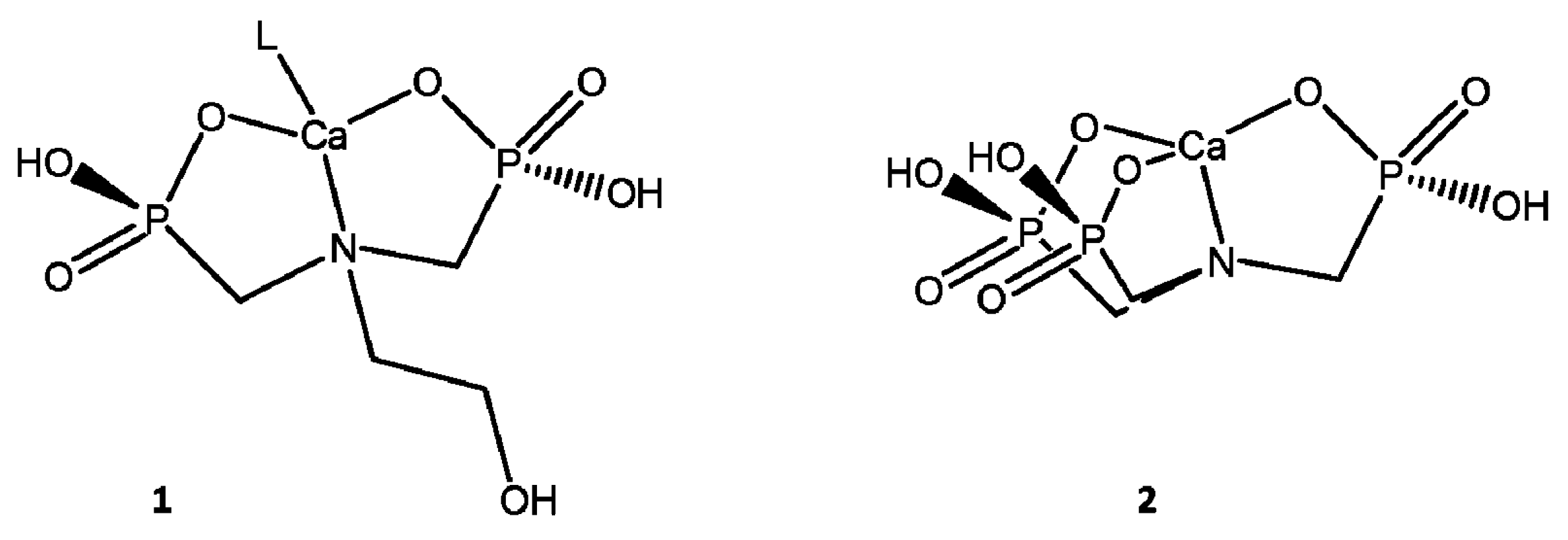
1. Introduction
2. Materials and Methods
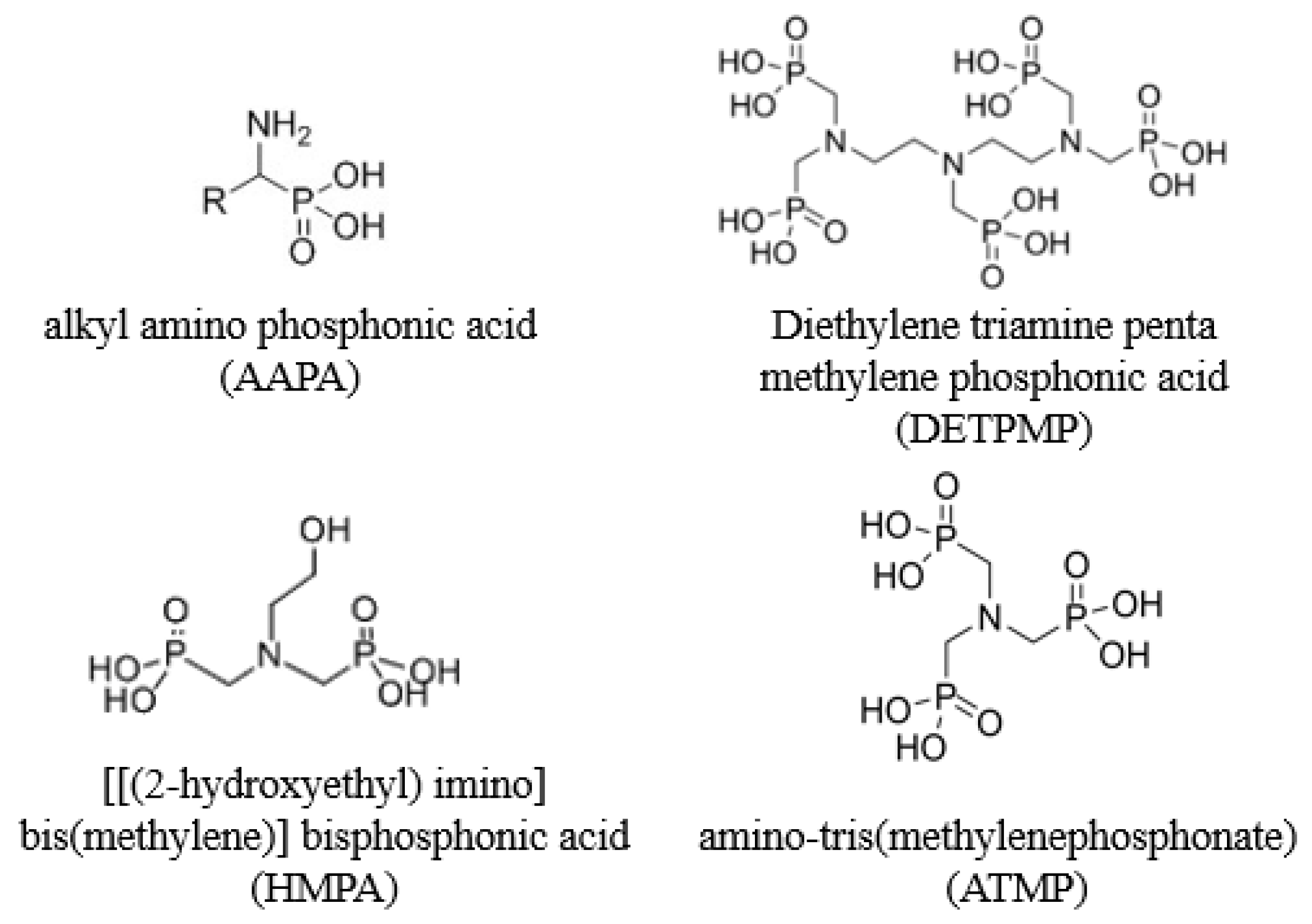
2.1. Materials
2.2. Synthetic Water Preparation
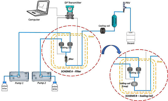
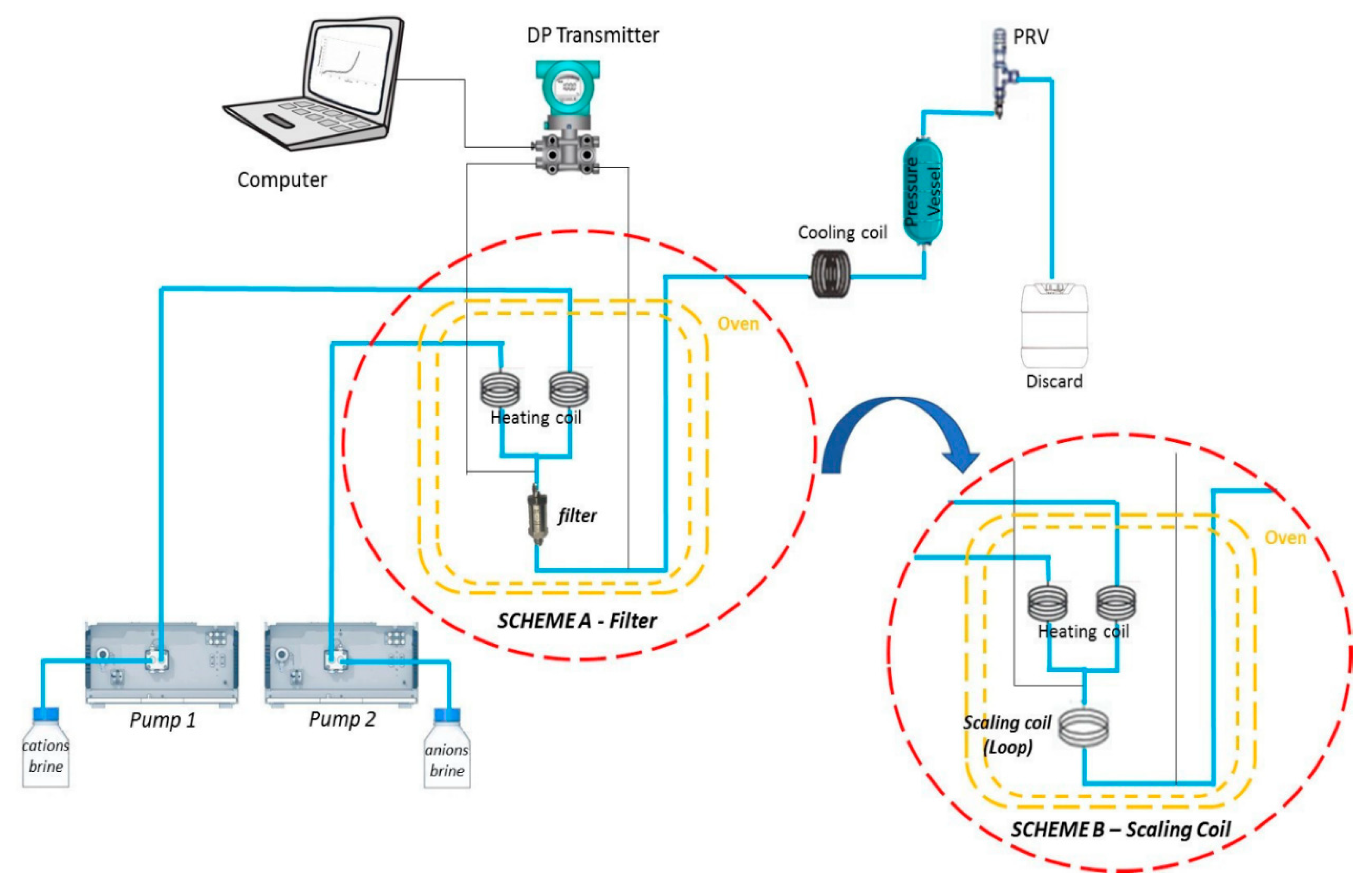
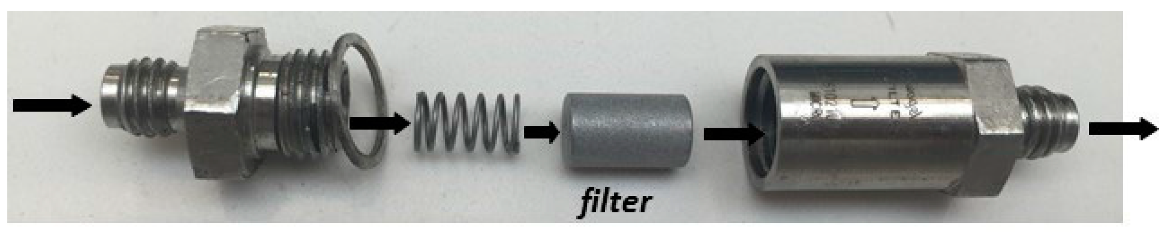
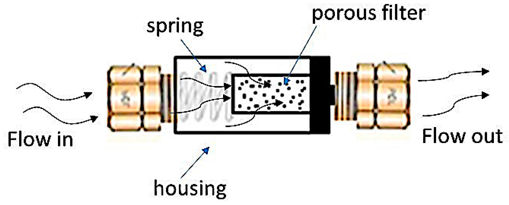
2.3. Determination of Scale Inhibitor MIC for Calcium Carbonate by Dynamic System in Filter or Scaling Coil
2.4. Deposition of Calcium Naphthenate by Dynamic Filter System
3. Results
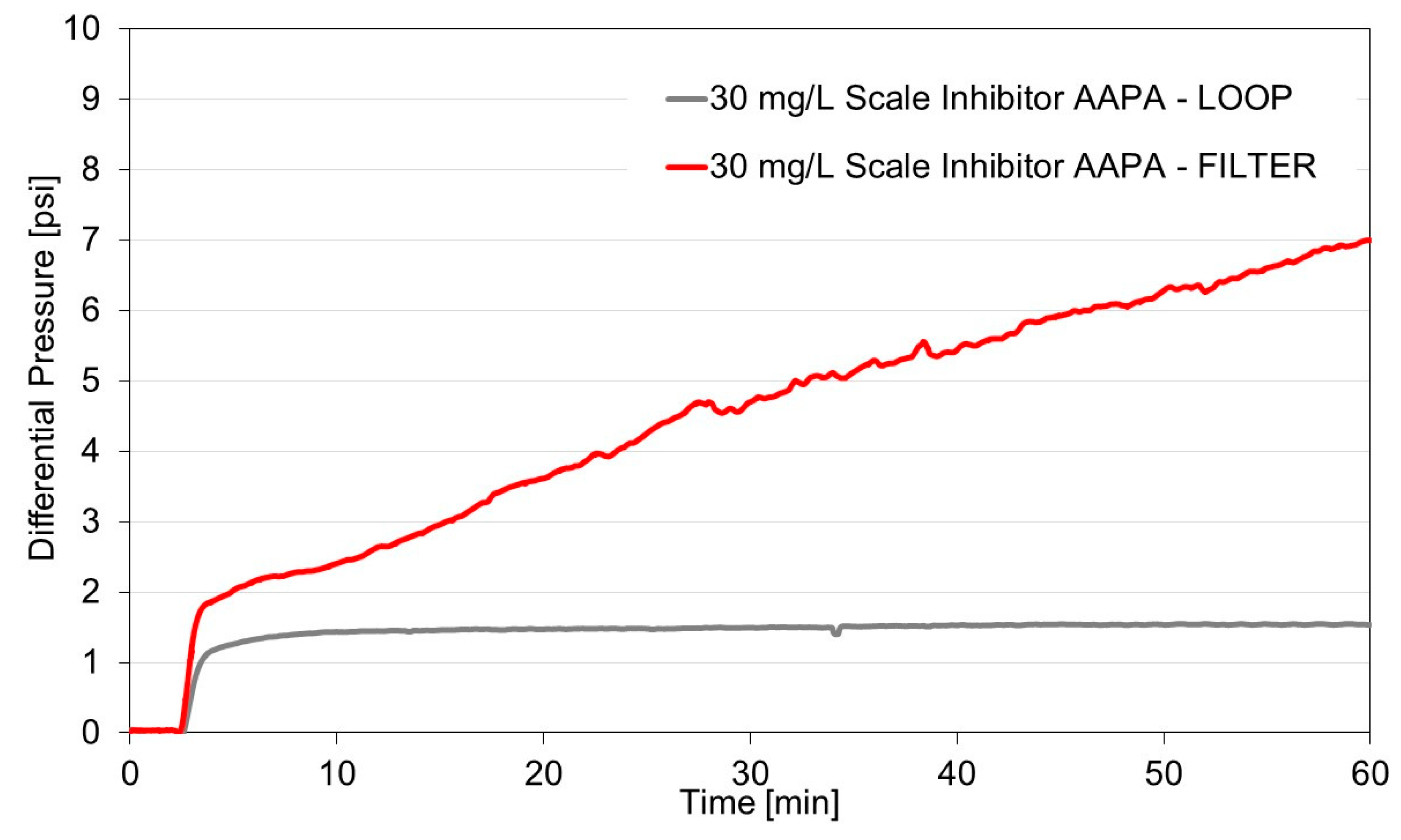
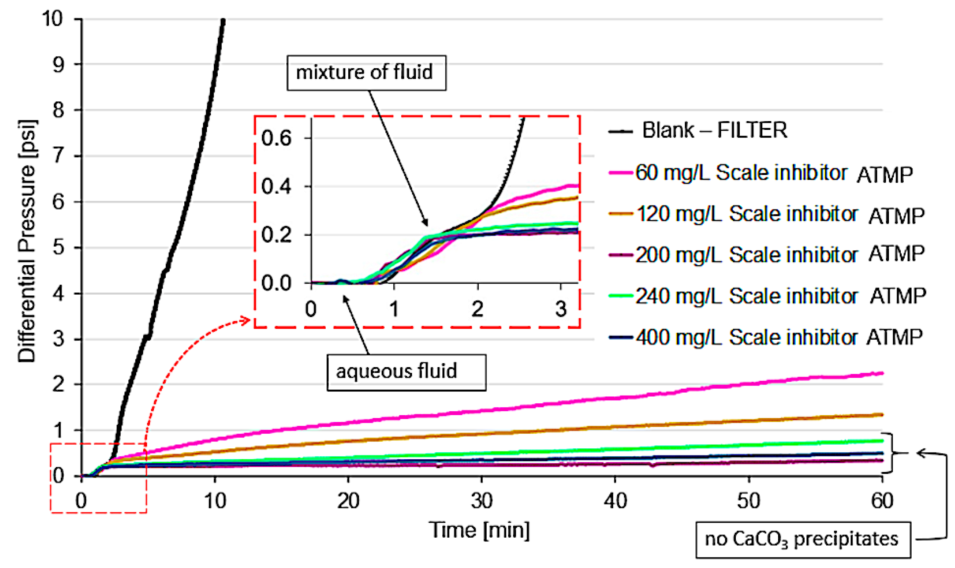
3.1. Dynamic Tests
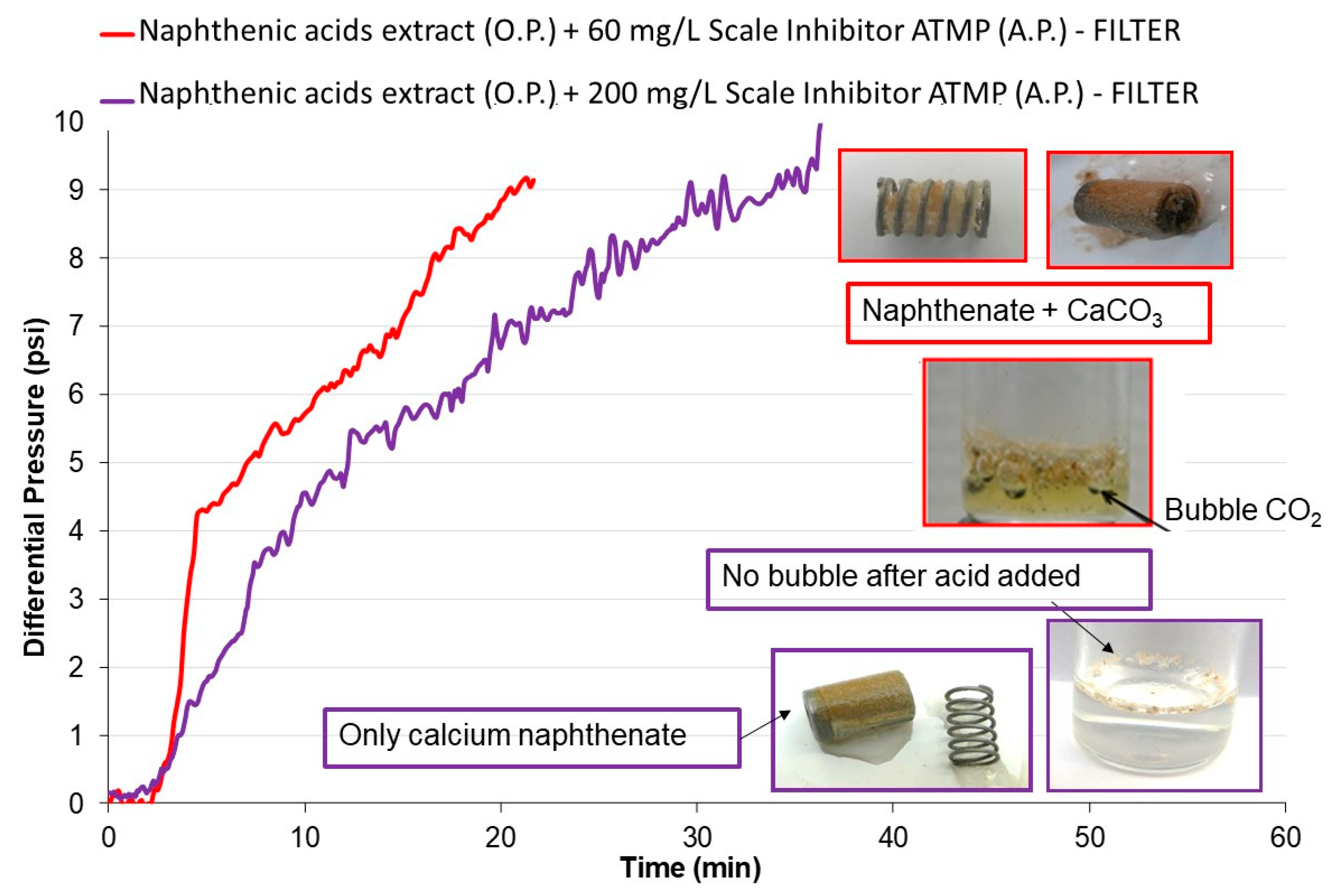
3.2. Case Study
4. Discussion
4.1. Dynamic Tests
4.2. Case Study
5. Conclusions
Supplementary Materials
Author Contributions
Funding
Acknowledgments
Conflicts of Interest
References
- Dyer, S.J.; Williams, H.L.; Graham, G.M.; Cummine, C.; Melvin, K.B.; Haider, F.; Gabb, A.E. Simulating calcium naphthenate formation and mitigation under laboratory conditions. Paper 100632-MS. In Proceedings of the International Oilfield Scale Symposium, Aberdeen, UK, 31 May–1 June 2006. [Google Scholar] [CrossRef]
- Frenier, W.; Ziauddin, M.; Venkatesan, R. Organic Deposits in Oil and Gas Production, 3rd ed.; Society of Petroleum Engineers: Richardson, TX, USA, 2010. [Google Scholar]
- Kumar, S.; Naiya, T.K.; Kumar, T. Developments in oilfield scale handling towards green technology-A review. J. Petrol. Sci. Eng. 2018, 169, 428–444. [Google Scholar] [CrossRef]
- Østvold, T.; Randhol, P. Kinetics of CaCO3 scale formation. The influence of temperature, supersaturation and ionic composition. Paper SPE 68302. In Proceedings of the International Symposium on Oilfield Scale, Aberdeen, UK, 30–31 January 2001. [Google Scholar] [CrossRef]
- Goodwin, N.; May, M.; Nichols, D.; Graham, G. Scale deposition and hydrodynamics—Benchtop to pilot rig. Paper SPE 190756-MS. In Proceedings of the International Oilfield Scale Conference and Exhibition, Aberdeen, UK, 20–21 June 2018. [Google Scholar] [CrossRef]
- Venâncio, F.; Rosário, F.F.; Cajaiba, J. Use of a dynamic system and reflectance measurements to assess the impact of monoethylene glycol on calcium carbonate scale. J. Petrol. Sci. Eng. 2018, 165, 581–585. [Google Scholar] [CrossRef]
- Graham, G.M.; Boak, L.S.; Hobden, C.M. Examination of the effect of generically different scale inhibitor species (PPCA and DETPMP) on the adherence and growth of barium sulphate scale on metal surfaces. Paper SPE 68298. In Proceedings of the International Symposium on Oilfield Scale, Aberdeen, UK, 30–31 January 2001. [Google Scholar] [CrossRef]
- Jordan, M.M.; Hiscox, I.; Dalton, J.F.; Mackie, J.; Kemp, S. The design and deployment of enhanced scale dissolver/squeeze treatment in subsea horizontal production wells, North Sea Basin. Paper SPE 73717-MS. In Proceedings of the International Symposium on Oilfield Chemistry, Lafayette, LA, USA, 20–21 February 2002. [Google Scholar] [CrossRef]
- Graham, G.M.; Collins, I.R.; Stalker, R.; Littlehales, I.J. The importance of appropriate laboratory procedures for the determination of scale inhibitor performance. Paper SPE 74679-MS. In Proceedings of the International Symposium on Oilfield Scale, Aberdeen, UK, 30–31 January 2002. [Google Scholar] [CrossRef]
- NACE. NACE 31105-Dynamic Scale Inhibitor Evaluation Apparatus and Procedures in Oil and Gas Production; NACE Int.: Houston, TX, USA, 2005. [Google Scholar]
- NACE. NACE 0374-Laboratory Screening Tests to Determine the Ability of Scale Inhibitors to Prevent the Precipitation of Calcium Sulfate and Calcium Carbonate from Solution (for Oil and Gas Production Systems); NACE Int.: Houston, TX, USA, 2016. [Google Scholar]
- Penna, M.O.; Alvim, F.B.; Nunes, G.G.; Gonçalves, A.C.H. Comparação entre os métodos de microbalança de cristal de quartzo e eficiência estática e dinâmica para a avaliação de inibidores de incrustação (CaCO3 e BaSO4). ABRACO 2014. In Proceedings of the INTERCORR, Fortaleza, Brazil, 19–23 May 2014. [Google Scholar]
- Graham, A.L.; Williams, H.L.; Tau, L.A.; Wennberg, K.E. Design and application of a novel HT/HP “stirred reactor” test rig to study scale formation and control. Paper SPE 93425. In Proceedings of the International Symposium on Oilfield Chemistry, Houston, TX, USA, 2–4 February 2005. [Google Scholar] [CrossRef]
- Chibowski, E.; Hołysz, L.; Terpiłowski, K. Effect of magnetic field on deposition and adhesion of calcium carbonate particles on different substrates. J. Adhes. Sci. Technol. 2003, 17, 2005–2021. [Google Scholar] [CrossRef]
- Khormali, A.; Petrakov, D.G.; Moein, M.J.A. Experimental analysis of calcium carbonate scale formation and inhibition in waterflooding of carbonate reservoirs. J. Petrol. Sci. Eng. 2016, 147, 843–850. [Google Scholar] [CrossRef]
- Moghadasi, J.; Jamialahmadi, M.; Müller-Steinhagen, H.; Sharif, A.; Ghalambor, A.; Izadpanah, M.R.; Motaie, E. Scale formation in Iranian oil reservoir and production equipment during water injection. Paper SPE 80406-MS. In Proceedings of the International Symposium on Oilfield Scale, Aberdeen, UK, 29–30 January 2003. [Google Scholar] [CrossRef]
- Baugh, T.D.; Lee, J.; Winters, K.; Waters, J.; Wilcher, J. A fast and information-rich test method for scale inhibitor performance. In Proceedings of the Offshore Technology Conference, Houston, Texas, USA, 30 April–3 May 2012. [Google Scholar] [CrossRef]
- Graham, A.L.; Boak, L.S.; Neville, A.; Sorbie, K.S. How minimum inhibitor concentration (MIC) and sub-MIC concentrations affect bulk precipitation and surface scaling rates. Paper SPE 93311. In Proceedings of the International Symposium on Oilfield Chemistry, Houston, TX, USA, 2–4 February 2005. [Google Scholar] [CrossRef]
- Kelland, M.A. Effect of various cations on the formation of calcium carbonate and barium sulfate scale with and without scale inhibitors. Ind. Eng. Chem. Res. 2011, 50, 5852–5861. [Google Scholar] [CrossRef]
- Abdel-Aal, N.; Sawada, K. Inhibition of adhesion and precipitation of CaCO3 by aminopolyphosphonate. J. Cryst. Growth 2003, 256, 188–200. [Google Scholar] [CrossRef]
- Euvrard, M.; Membrey, F.; Filiatre, C.; Pignolet, C.; Foissy, A. Kinetic astudy of the electrocrystallization of calcium carbonate on metallic substrates. J. Cryst. Growth 2006, 291, 428–435. [Google Scholar] [CrossRef]
- Garcia, C.; Courbin, G.; Ropital, F.; Fiaud, C. Study of the scale inhibition by HEDP in a channel flow cell using a quartz Crystal microbalance. Electrochim. Acta 2001, 46, 973–985. [Google Scholar] [CrossRef]
- Morizot, A.P.; Neville, A.; Hodgkiess, T. Studies of the deposition of CaCO3 on a stainless steel surface by a novel electrochemical technique. J. Cryst. Growth 1999, 198–199, 738–743. [Google Scholar] [CrossRef]
- Vazirian, M.M.; Charpentier, T.V.J.; Penna, M.O.; Neville, A. Surface inorganic scale formation in oil and gas industry: As adhesion and deposition processes. J. Petrol. Sci. Eng. 2016, 137, 22–32. [Google Scholar] [CrossRef]
- Schalge, A.L.; Dormish, F.L. The evaluation of scale inhibitors for high BaSO4 scaling potential using a new tube/filter blocking apparatus. Paper SPE 18490. In Proceedings of the International Symposium on Oilfield Chemistry, Houston, TX, USA, 8–10 February 1989. [Google Scholar] [CrossRef]
- Nichols, D.A.; Rosário, F.F.; Bezerra, M.C.M.; Gorringe, S.E.; Williams, H.L.; Graham, G.M. Calcium naphthenate in complex production systems—Evaluation and chemical inhibition challenges. Paper SPE 169756-MS. In Proceedings of the International Oilfield Scale Conference and Exhibition, Aberdeen, UK, 14–15 May 2014. [Google Scholar] [CrossRef]
- Williams, H.L.; Dyer, S.J.; Graham, G.M. Understanding the factors influencing the formation and control of calcium naphthenate solids and stabilized emulsions using a novel laboratory flow rig. Paper SPE 106499. In Proceedings of the International Symposium on Oilfield Chemistry, Houston, TX, USA, 28 February–2 March 2007. [Google Scholar] [CrossRef]
- Bertelli, J.N.; Dip, R.M.M.; Pires, R.V.; Albuquerque, F.C.; Lucas, E.F. Shear rheology using De Noüy Ring to evaluate formation and inhibition of calcium naphthenate at the water/oil interface. Energy Fuels 2014, 28, 1726–1735. [Google Scholar] [CrossRef]
- Bazin, B.; Kohler, N.; Zaitoun, A. Some insights into the tube-blocking-test method to evaluate the efficiency of mineral scale inhibitors. Paper SPE 96560-MS. In Proceedings of the Annual Technical Conference and Exhibition, Dallas, TX, USA, 9–12 October 2005. [Google Scholar] [CrossRef]
- Kartnaller, V.; Venâncio, F.; Rosário, F.F.; Cajaiba, J. Application of multiple regression and design of experiments for modelling the effect of monoethylene glycol in the calcium carbonate scaling process. Molecules 2018, 23, 860. [Google Scholar] [CrossRef] [PubMed]
- Cao, M.; Ming, X.; He, K.; Li, L.; Shen, S. Effect of macro-, micro- and nano-calcium carbonate on properties of cementitious composites—A review. Materials 2019, 12, 781. [Google Scholar] [CrossRef] [PubMed]
- Swagelok. FW, F and TF Series Filters Electronic Catalog. 2017. Available online: https://www.swagelok.com/downloads/webcatalogs/en/MS-01-92.pdf (accessed on 28 May 2019).
- Shaw, S.S.; Welton, T.D.; Sorbie, K.S. The relation between barite inhibition by phosphonate scale inhibitors and the structures of phosphonate-metal complexes. Paper SPE 155114. In Proceedings of the International Conference and Exhibition on Oilfield Scale, Aberdeen, UK, 30–31 May 2012. [Google Scholar] [CrossRef]


| Ion | Concentration/(mg/L) |
|---|---|
| Sodium | 69,529 |
| Calcium | 18,000 |
| Barium | 300 |
| Strontium | 1700 |
| Chloride | 140,000 |
| Bicarbonate | 1000 |
| SCHEME A | SCHEME B | ||
|---|---|---|---|
| Sintered Metal Filter | Scaling Coil (Conventional Tube Blocking Test—TBT) | ||
| Flow | Turbulent | Flow | Laminar |
| Filter dimensions (diameter × height) | 7.67 mm × 12.65 mm | Scaling coil length | 1 m (1000 mm) |
| Filter nominal pore size Filter pore size range | 7 µm 5–10 µm | Scaling coil ID | 0.5 mm (500 µm) |
| Filter metallurgy | 316 stainless steel | Scaling coil metallurgy | 316 stainless steel |
| Combined flow rate | 10 mL/min | Combined flow rate | 10 mL/min |
| Run test duration | 1 h | Run test duration | 1 h |
| Failure criteria | Increase in ΔP ≥ 1 psi | Failure criteria | Increase in ΔP ≥ 1 psi |
| Temperature | 80 °C | Temperature | 80 °C |
| Pressure | 44 psi | Pressure | 44 psi |
| Inhibitor | N/P Ratio | MIC (mg/L) in TBT Dynamic System | MIC (mg/L) in Dynamic Filter System |
|---|---|---|---|
| AAPA | 1.0 | 30 | 90 |
| DETPMP | 0.60 | 60 | 100 |
| HMPA | 0.50 | 60 | 100 |
| ATMP | 0.33 | 60 | 200 |
© 2019 by the authors. Licensee MDPI, Basel, Switzerland. This article is an open access article distributed under the terms and conditions of the Creative Commons Attribution (CC BY) license (http://creativecommons.org/licenses/by/4.0/).
Share and Cite
Velloso Alves de Souza, A.; Rosário, F.; Cajaiba, J. Evaluation of Calcium Carbonate Inhibitors Using Sintered Metal Filter in a Pressurized Dynamic System. Materials 2019, 12, 1849. https://doi.org/10.3390/ma12111849
Velloso Alves de Souza A, Rosário F, Cajaiba J. Evaluation of Calcium Carbonate Inhibitors Using Sintered Metal Filter in a Pressurized Dynamic System. Materials. 2019; 12(11):1849. https://doi.org/10.3390/ma12111849
Chicago/Turabian StyleVelloso Alves de Souza, Adriana, Francisca Rosário, and João Cajaiba. 2019. "Evaluation of Calcium Carbonate Inhibitors Using Sintered Metal Filter in a Pressurized Dynamic System" Materials 12, no. 11: 1849. https://doi.org/10.3390/ma12111849
APA StyleVelloso Alves de Souza, A., Rosário, F., & Cajaiba, J. (2019). Evaluation of Calcium Carbonate Inhibitors Using Sintered Metal Filter in a Pressurized Dynamic System. Materials, 12(11), 1849. https://doi.org/10.3390/ma12111849