Impact of Strain and Morphology on Magnetic Properties of Fe3O4/NiO Bilayers Grown on Nb:SrTiO3(001) and MgO(001)

 , , ,
, , , 
Abstract
1. Introduction
2. Materials and Methods
3. Results
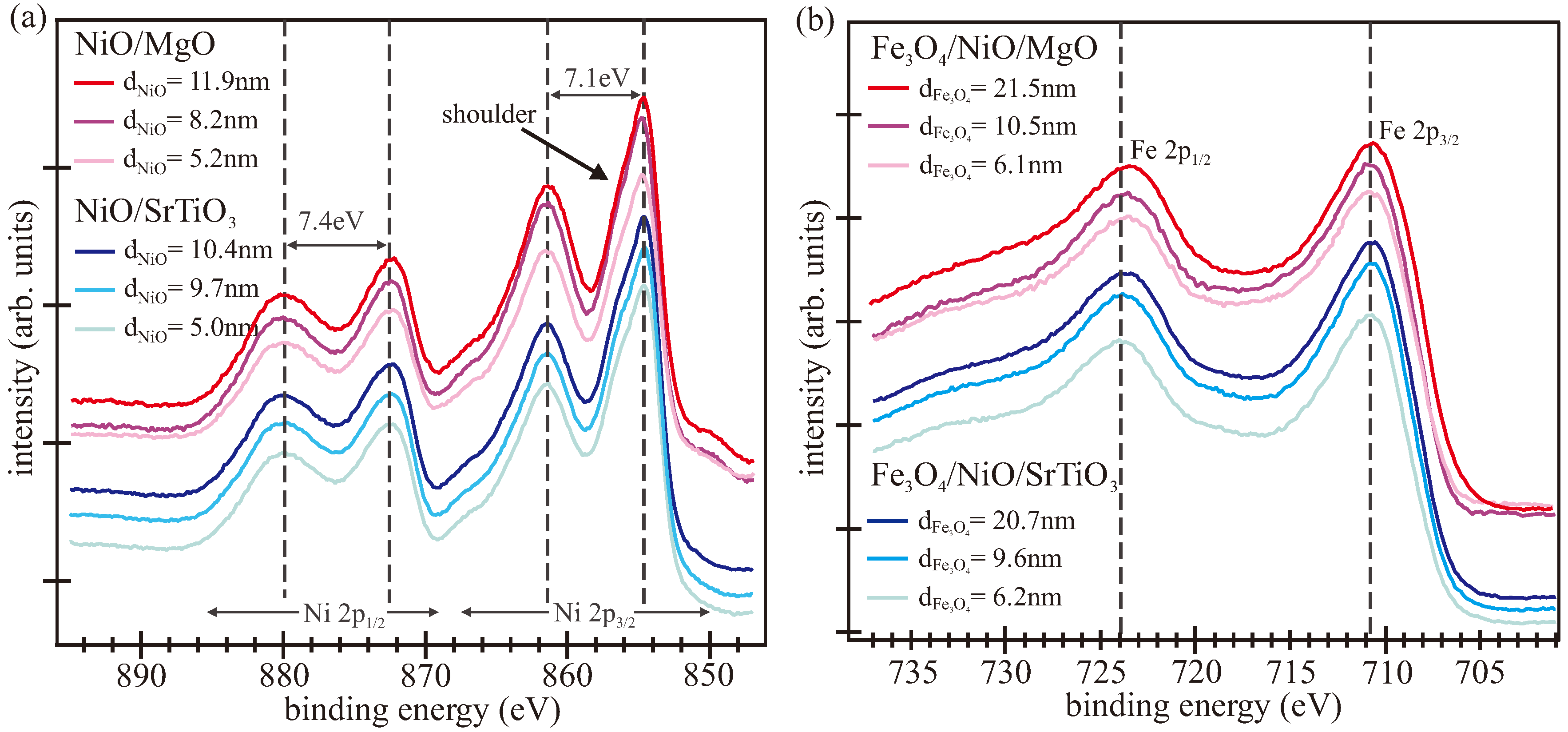
3.1. LEED/XPS
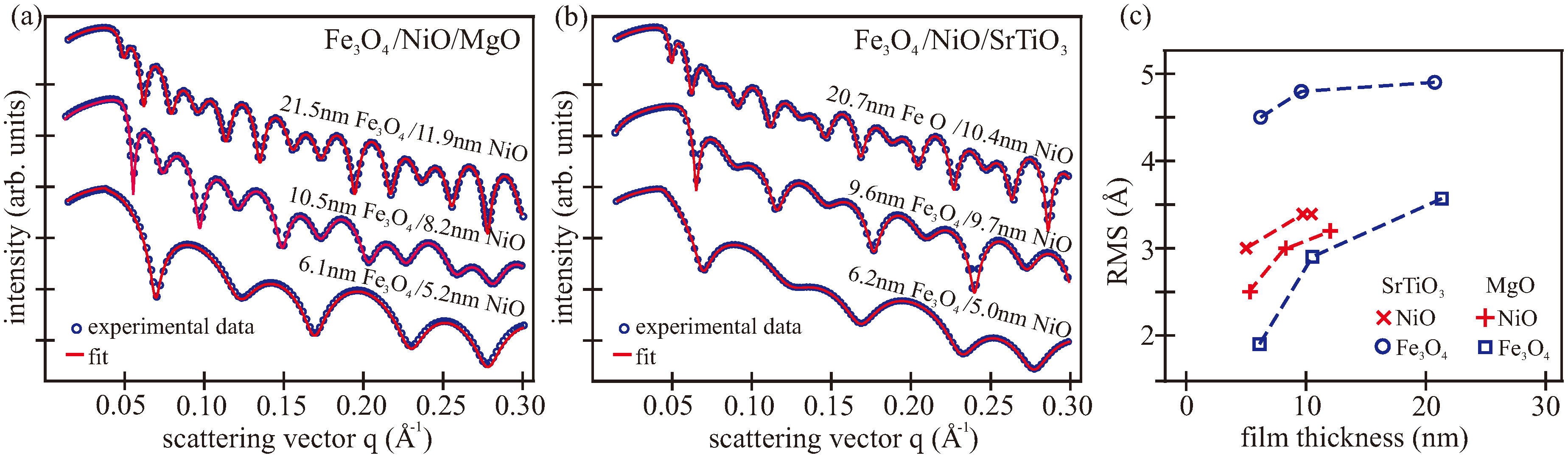
3.2. XRR/XRD
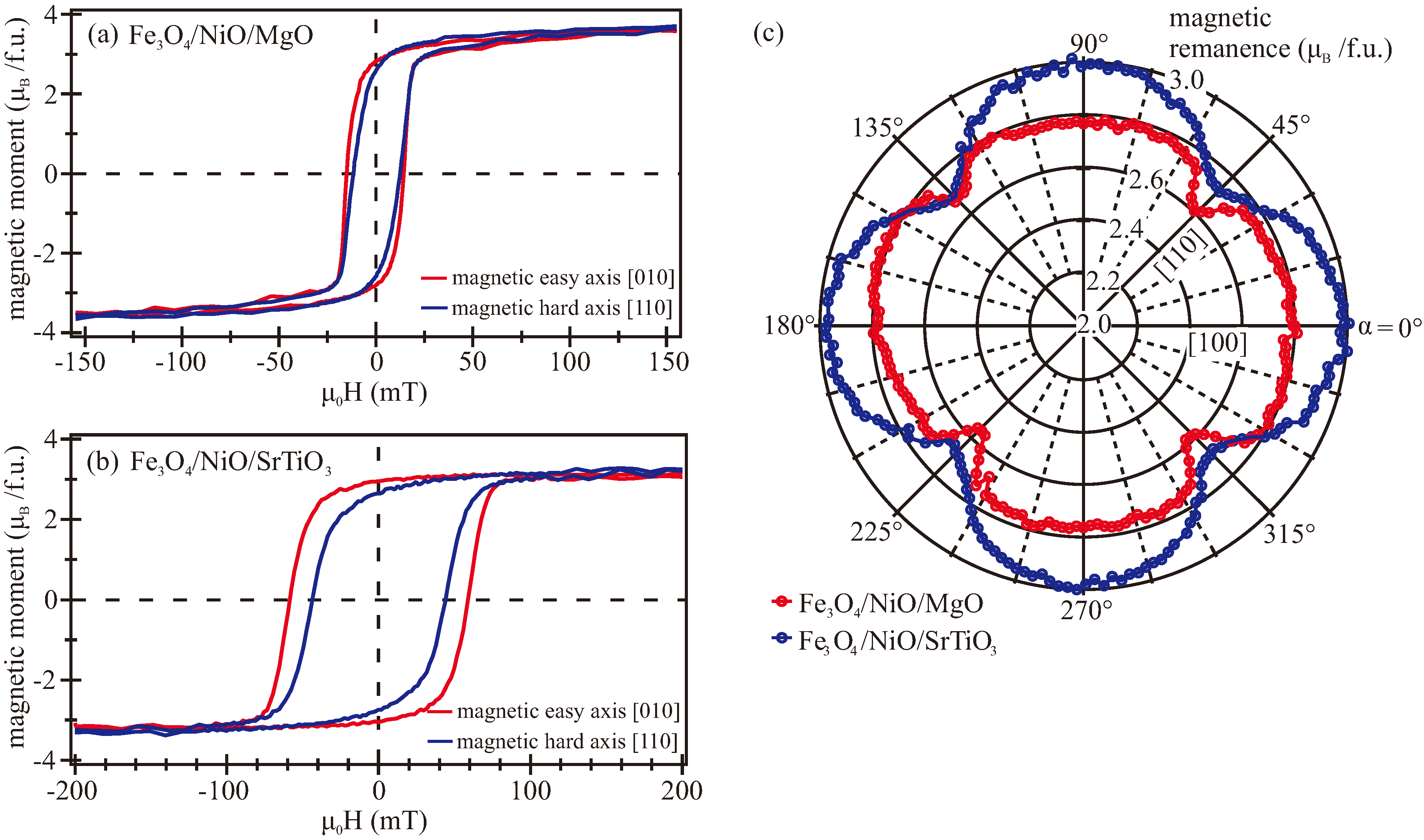
3.3. VSM
4. Discussion
5. Conclutions
Author Contributions
Funding
Acknowledgments
Conflicts of Interest
References
- Rao, C.N.R. Transition metal oxides. Annu. Rev. Phys. Chem. 1989, 40, 291–326. [Google Scholar] [CrossRef]
- Hoffmann, A.; Bader, S.D. Opportunities at the frontiers of spintronics. Phys. Rev. Appl. 2015, 4, 047001. [Google Scholar] [CrossRef]
- Bauer, G.E.W.; Saitoh, E.; van Wees, B.J. Spin caloritronics. Nat. Mater. 2012, 11, 391–399. [Google Scholar] [CrossRef] [PubMed]
- Moussy, J.B. From epitaxial growth of ferrite thin films to spin-polarized tunnelling. J. Phys. D Appl. Phys. 2013, 46, 143001. [Google Scholar] [CrossRef]
- Zhang, Z.; Satpathy, S. Electron states, magnetism, and the Verwey transition in magnetite. Phys. Rev. B 1991, 44, 13319–13331. [Google Scholar] [CrossRef]
- Cornell, R.; Schwertmann, U. The Iron Oxides: Structure, Properties, Reactions, Occurrences and Uses; Wiley-VCH GmbH & Co. KGaA: Weinheim, Germany, 2004. [Google Scholar]
- Seneor, P.; Fert, A.; Maurice, J.L.; Montaigne, F.; Petroff, F.; Vaurés, A. Large magnetoresistance in tunnel junctions with an iron oxide electrode. Appl. Phys. Lett. 1999, 74. [Google Scholar] [CrossRef]
- Kado, T. Large room-temperature inverse magnetoresistance in tunnel junctions with a Fe3O4 electrode. Appl. Phys. Lett. 2008, 92, 092502. [Google Scholar] [CrossRef]
- Marnitz, L.; Rott, K.; Niehörster, S.; Klewe, C.; Meier, D.; Fabretti, S.; Witziok, M.; Krampf, A.; Kuschel, O.; Schemme, T.; et al. Sign change in the tunnel magnetoresistance of Fe3O4/MgO/Co-Fe-B magnetic tunnel junctions depending on the annealing temperature and the interface treatment. AIP Adv. 2015, 5, 047103. [Google Scholar] [CrossRef]
- Wada, E.; Watanabe, K.; Shirahata, Y.; Itoh, M.; Yamaguchi, M.; Taniyama, T. Efficient spin injection into GaAs quantum well across Fe3O4 spin filter. Appl. Phys. Lett. 2010, 96, 102510. [Google Scholar] [CrossRef]
- Ramos, R.; Anadón, A.; Lucas, I.; Uchida, K.; Algarabel, P.A.; Morellón, L.; Aguirre, M.H.; Saitoh, E.; Ibarra, M.R. Thermoelectric performance of spin Seebeck effect in Fe3O4/Pt-based thin film heterostructures. APL Mater. 2016, 4, 104802. [Google Scholar] [CrossRef]
- Ramos, R.; Kikkawa, T.; Uchida, K.; Adachi, H.; Lucas, I.; Aguirre, M.H.; Algarabel, P.; Morellón, L.; Maekawa, S.; Saitoh, E.; et al. Observation of the spin Seebeck effect in epitaxial Fe3O4 thin films. Appl. Phys. Lett. 2013, 102, 072413. [Google Scholar] [CrossRef]
- Uchida, K.I.; Adachi, H.; Kikkawa, T.; Kirihara, A.; Ishida, M.; Yorozu, S.; Maekawa, S.; Saitoh, E. Thermoelectric generation based on spin Seebeck effects. Proc. IEEE 2016, 104, 1946–1973. [Google Scholar] [CrossRef]
- Verwey, E.J.W. Electronic conduction of magnetite (Fe3O4) and its transition point at low temperatures. Nature 1939, 144, 327–328. [Google Scholar] [CrossRef]
- Yoshida, J.; Iida, S. X-ray diffraction study on the low temperature phase of magnetite. J. Phys. Soc. Jpn. 1977, 42, 230–237. [Google Scholar] [CrossRef]
- Kato, K.; Iida, S. Observation of ferroelectric hysteresis loop of Fe3O4 at 4.2 K. J. Phys. Soc. Jpn. 1982, 51, 1335–1336. [Google Scholar] [CrossRef]
- Alexe, M.; Ziese, M.; Hesse, D.; Esquinazi, P.; Yamauchi, K.; Fukushima, T.; Picozzi, S.; Gösele, U. Ferroelectric switching in multiferroic magnetite (Fe3O4) thin films. Adv. Mater. 2009, 21, 4452. [Google Scholar] [CrossRef]
- Meiklejohn, W.H.; Bean, C.P. New Magnetic Anisotropy. Phys. Rev. 1956, 102, 1413–1414. [Google Scholar] [CrossRef]
- Srinivasan, G.; Seehra, M.S. Magnetic susceptibilities, their temperature variation, and exchange constants of NiO. Phys. Rev. B 1984, 29, 6295. [Google Scholar] [CrossRef]
- James, M.; Hibma, T. Thickness-dependent relaxation of NiO(001) overlayers on MgO(001) studied by X-ray diffraction. Surf. Sci. 1999, 433–435, 718–722. [Google Scholar] [CrossRef]
- Lin, W.; Chen, K.; Zhang, S.; Chien, C.L. Enhancement of thermally injected spin current through an antiferromagnetic insulator. Phys. Rev. Lett. 2016, 116, 186601. [Google Scholar] [CrossRef] [PubMed]
- Prakash, A.; Brangham, J.; Yang, F.; Heremans, J.P. Spin Seebeck effect through antiferromagnetic NiO. Phys. Rev. B 2016, 94, 014427. [Google Scholar] [CrossRef]
- Hashimoto, S.; Peng, J.L.; Gibson, W.; Schowalter, L.J.; Fathauer, R.W. Strain measurement of epitaxial CaF2 on SI (111) by MeV ion channeling. Appl. Phys. Lett. 1985, 47. [Google Scholar] [CrossRef]
- Holanda, J.; Maior, D.S.; Santos, O.A.; Vilela-Leão, L.H.; Mendes, J.B.S.; Azevedo, A.; Rodríguez-Suárez, R.L.; Rezende, S.M. Spin-current to charge-current conversion and magnetoresistance in a hybrid structure of graphene and yttrium iron garnet. Appl. Phys. Lett. 2017, 111, 172405. [Google Scholar] [CrossRef]
- Hoogeboom, G.R.; Aqeel, A.; Kuschel, T.; Palstra, T.T.M.; van Wees, B.J. Negative spin Hall magnetoresistance of Pt on the bulk easy-plane antiferromagnet NiO. Appl. Phys. Lett 2017, 111, 052409. [Google Scholar] [CrossRef]
- Hou, D.; Qui, Z.; Barker, J.; Sato, K.; Yamamoto, K.; Vélez, S.; Gomez-Perez, J.M.; Hueso, L.E.; Casanova, F.; Saitoh, E. Tunable sign change of spin Hall magnetoresistance in Pt=NiO=YIG structures. Phys. Rev. Lett. 2017, 118, 147202. [Google Scholar] [CrossRef] [PubMed]
- Bertram, F.; Deiter, C.; Schemme, T.; Jentsch, S.; Wollschläger, J. Reordering between tetrahedral and octahedral sites in ultrathin magnetite films grown on MgO(001). J. Appl. Phys. 2013, 113, 184103. [Google Scholar] [CrossRef]
- Arora, S.K.; Wu, H.C.; Choudhary, R.J.; Shvets, I.V.; Mryasov, O.N.; Yao, H.; Ching, W.Y. Giant magnetic moment in epitaxial Fe3O4 thin films on MgO(100). Phys. Rev. B 2008, 77, 134443. [Google Scholar] [CrossRef]
- Arora, S.K.; Sofin, R.G.S.; Shvets, I.V.; Luysberg, M. Anomalous strain relaxation behavior of Fe3O4/MgO(100) heteroepitaxial system grown using molecular beam epitaxy. J. Appl. Phys. 2006, 100, 073908. [Google Scholar] [CrossRef]
- Wu, H.C.; Ramos, R.; Sofin, R.G.S.; Liao, Z.M.; Abid, M.; Shvets, I.V. Transversal magneto-resistance in epitaxial Fe3O4 and Fe3O4/NiO exchange biased system. Appl. Phys. Lett. 2012, 101, 052402. [Google Scholar] [CrossRef]
- Gatel, C.; Snoeck, E.; Serin, V.; Fert, A.R. Epitaxial growth and magnetic exchange anisotropy in Fe3O4/NiO bilayers grown on MgO(001) and Al2O3(0001). Eur. J. Phys. B 2005, 45. [Google Scholar] [CrossRef]
- Wu, H.C.; Arora, S.K.; Mryasov, O.N.; Shvets, I.V. Antiferromagnetic interlayer exchange coupling between Fe3O4 layers across a nonmagnetic MgO dielectric layer. Appl. Phys. Lett. 2008, 92, 182502. [Google Scholar] [CrossRef]
- Schemme, T.; Kuschel, O.; Bertram, F.; Kuepper, K.; Wollschläger, J. Structure and morphology of epitaxially grown Fe3O4/NiO bilayers on MgO(001). Thin Solid Films 2015, 589, 526–533. [Google Scholar] [CrossRef]
- Chen, Y.Z.; Sun, J.R.; Han, Y.N.; Xie, X.Y.; Shen, J.; Rong, C.B.; He, S.L.; Shen, B.G. Microstructure and magnetic properties of strained Fe3O4 films. J. Appl. Phys. 2008, 103, 07D703. [Google Scholar] [CrossRef]
- Monti, M.; Sanz, M.; Oujja, M.; Rebollar, E.; Castillejo, M.; Pedrosa, F.J.; Bollero, A.; Camarero, J.; Cunado, J.L.F.; Nemes, N.M.; et al. Room temperature in-plane <100> magnetic easy axis for Fe3O4/SrTiO3(001):Nb grown by infrared pulsed laser deposition. J. Appl. Phys. 2013, 114, 223902. [Google Scholar] [CrossRef]
- Liu, X.H.; Liu, W.; Zhang, Z.D. Evolution of magnetic properties in the vicinity of the Verwey transition in Fe3O4 thin films. Phys. Rev. B 2017, 96, 094405. [Google Scholar] [CrossRef]
- Kuschel, O.; Buß, R.; Spiess, W.; Schemme, T.; Wöllermann, J.; Balinski, K.; N’Diaye, A.T.; Kuschel, T.; Wollschläger, J.; Kuepper, K. From Fe3O4/NiO bilayers to NiFe2O4-like thin films through Ni interdiffusion. Phys. Rev. B 2016, 94, 094423. [Google Scholar] [CrossRef]
- Chern, G.; Cheng, C. Interface matching in oxides of rocksalt/rocksalt(001) and rocksalt/perovskite(001). J. Vac. Sci. Technol. 1999, A17. [Google Scholar] [CrossRef]
- Kennedy, R.J. The growth of iron oxide, nickel oxide and cobalt oxide thin films by laser ablation from metal targets. IEEE Trans. Magn. 1995, 31, 3829–3831. [Google Scholar] [CrossRef]
- Zhang, K.H.L.; Wu, R.; Tang, F.; Li, W.; Oropeza, R.E.; Qiao, L.; Lazarov, V.K.; Du, Y.; Payne, D.J.; MacManus-Driscoll, J.L.; et al. Electronic structure and band alignment at the NiO and SrTiO3 p-n heterojunctions. Appl. Mater. Interfaces 2017, 9, 26549–26555. [Google Scholar] [CrossRef] [PubMed]
- Pilard, M.; Ersen, O.; Cherifi, S.; Carvello, B.; Roiban, L.; Muller, B.; Scheurer, F.; Ranno, L.; Boeglin, C. Magnetic properties of coupled ultrathin NiO/Fe3O4 (001) films. Phys. Rev. B 2007, 76, 214436. [Google Scholar] [CrossRef]
- Kuepper, K.; Kuschel, O.; Pathé, N.; Schemme, T.; Schmalhorst, J.; Thomas, A.; Arenholz, E.; Gorgoi, M.; Ovsyannikov, R.; Bartkowski, S.; et al. Electronic and magnetic structure of epitaxial Fe3O4(001)/NiO heterostructures grown on MgO(001) and Nb-doped SrTiO3(001). Phys. Rev. B 2016, 94, 024401. [Google Scholar] [CrossRef]
- Krug, I.P.; Hillebrecht, F.U.; Haverkort, M.W.; Tanaka, A.; Tjeng, L.H.; Gomonay, H.; Fraile-Rodriguez, A.; Nolting, F.; Cramm, S.; Schneider, C.M. Impact of interface orientation on magnetic coupling in highly ordered systems: A case study of the low-indexed Fe3O4/NiO interfaces. Phys. Rev. B 2008, 78, 064427. [Google Scholar] [CrossRef]
- Wang, H.Q.; Gao, W.; Altman, E.I.; Heinrich, V.E. Studies of the electronic structure at the Fe3O4-NiO interface. J. Vac. Sci. Technol. A 2004, 22. [Google Scholar] [CrossRef]
- Parratt, L. Surface studies of solids by total reflection of x-rays. Rev. Mod. Phys. 1954, 95. [Google Scholar] [CrossRef]
- Névot, L.; Croce, P. Caractérisation des surfaces par réflexion rasante de rayons X. Application á l’étude du polissage de quelques verres silicates. Rev. Phys. Appl. 1980, 15, 761–779. [Google Scholar] [CrossRef]
- Als-Nielsen, J.; McMorrow, D. Elements of Modern X-Ray Physics; John Wiley & Sons, Ltd.: Hoboken, NJ, USA, 2001. [Google Scholar]
- Henzler, M. Measurement of surface defects by low-energy electorn diffraction. Appl. Phys. A 1984, 34, 205–214. [Google Scholar] [CrossRef]
- Pentcheva, R.; Moritz, W.; Rundgren, J.; Frank, S.; Schrupp, D.; Scheffler, M. Acombined DFT/LEED-approach for complex oxide surface structure determination: Fe3O4(001). Surf. Sci. 2008, 602, 1299–1305. [Google Scholar] [CrossRef]
- Korecki, J.; Handke, B.; Spiridis, N.; Slezak, T.; Flis-Kabulska, F.; Haber, J. Size effects in epitaxial films of magnetite. Thin Solid Films 2002, 412, 14–23. [Google Scholar] [CrossRef]
- Anderson, J.F.; Kuhn, M.; Diebold, U.; Shaw, K.; Stoyanov, P.; Lind, D. Surface structure and morphology of Mg-segregated epitaxial Fe3O4(001) thin films on MgO(001). Phys. Rev. B 1997, 56. [Google Scholar] [CrossRef]
- Bliem, R.; McDermott, E.; Ferstl, P.; Setvin, M.; Gamba, O.; Pavelec, J.; Schneider, M.A.; Schmid, M.; Diebold, U.; Blaha, P.; et al. Subsurface cation vacancy stabilization of the magnetite (001) surface. Science 2014, 346, 1215–1218. [Google Scholar] [CrossRef] [PubMed]
- Nesbitt, H.; Legrand, D.; Bancroft, G. Interpretation of Ni2p XPS spectra of Ni conductors and Ni insulators. Phys. Chem. Miner. 2000, 27, 357–366. [Google Scholar] [CrossRef]
- Grosvenor, A.P.; Biesinger, M.C.; Smart, R.S.C.; McIntyre, N.S. New interpretations of XPS spectra of nickel metal and oxides. Surf. Sci. 2006, 600, 1771–1779. [Google Scholar] [CrossRef]
- Uhlenbrock, S.; Scharfschwerdtt, C.; Neumannt, M.; Illing, G.; Freund, H.J. The influence of defects on the Ni 2p and O 1s XPS of NiO. J. Phys. Condens. Matter 1992, 4, 7973–7978. [Google Scholar] [CrossRef]
- Soriano, L.; Preda, I.; Gutiérrez, A.; Palacín, S.; Abbate, M.; Vollmer, A. Surface effects in the Ni 2p x-ray photoemission spectra of NiO. Phys. Rev. B 2007, 75, 233417. [Google Scholar] [CrossRef]
- Mansour, A.N. Characterization of NiO by XPS. Surf. Sci. Spectra 1994, 3. [Google Scholar] [CrossRef]
- Carley, A.; Jackson, S.; O’Shea, J.N.; Roberts, M.W. The formation and characterisation of Ni3+—An X-ray photoelectron spectroscopic investigation of potassium-doped Ni(110)-O. Surf. Sci. Lett. 1999, 440, L868–L874. [Google Scholar] [CrossRef]
- Yamashita, T.; Hayes, P. Analysis of XPS spectra of Fe2+ and Fe3+ ions in oxide materials. Appl. Surf. Sci. 2008, 254, 2441–2449. [Google Scholar] [CrossRef]
- Fujii, T.; de Groot, F.M.F.; Sawatzky, G.A.; Voogt, F.C.; Hibma, T.; Okada, K. In situ XPS analysis of various iron oxide films grown by NO2-assisted molecular-beam epitaxy. Phys. Rev. B 1999, 59. [Google Scholar] [CrossRef]
- Henke, B.; Gullikson, E.; Davis, J. X-ray interactions: Photoabsorption, scattering, transmission, and reflection at E = 50–30000 eV, Z = 1–92. At. Data Nucl. Data 1993, 54, 181–342. [Google Scholar] [CrossRef]
- Pimpinelli, A.; Villain, J. Physics of Crystal Growth; Campbridge University Press: Campbridge, UK, 1998. [Google Scholar]
- Jeng, H.T.; Guo, G.Y. First-principles investigations of the electronic structure and magnetocrystalline anisotropy in strained magnetite Fe3O4. Phys. Rev. B 2002, 65, 094429. [Google Scholar] [CrossRef]
- Margulies, D.T.; Parker, F.T.; Rudee, M.L.; Spada, F.E.; Chapman, J.N.; Aitchison, P.R.; Berkowitz, A.E. Origin of the anomalous magnetic behavior in single crystal Fe3O4 films. Phys. Rev. Lett. 1997, 79. [Google Scholar] [CrossRef]
- Fleischer, K.; Mauit, O.; Shvets, I.V. Stability and capping of magnetite ultra-thin films. Appl. Phys. Lett. 2014, 104, 192401. [Google Scholar] [CrossRef]
- Matthews, J.W.; Blakeslee, A.E. Defects in epitaxial multilayers: I. Misfit dislocations. J. Cryst. Growth 1974, 27, 118–125. [Google Scholar] [CrossRef]
- Every, A.G.; McCurdy, A.K. Table 7, Cubic System. Binary Compounds; Springer Materials—The Landolt- Boernstein Database; Springer: Berlin/Heidelberg, Germany, 1992. [Google Scholar]
- Balakrishnan, K.; Arora, S.K.; Shvets, I.V. Strain relaxation studies of the Fe3O4/MgO(100) heteroepitaxial system grown by magnetron sputtering. J. Phys. Condens. Matter 2004, 16. [Google Scholar] [CrossRef]
- Cheng, J.; Sterbinsky, G.E.; Wessels, B.W. Magnetic and magneto-optical properties of heteroepitaxial magnetite thin films. J. Cryst. Growth 2008, 310, 3730–3734. [Google Scholar] [CrossRef]
- Dho, J.; Kim, B.; Ki, S. Substrate effects on in-plane magnetic anisotropy and Verwey transition temperatures of (100) magnetite (Fe3O4) films. IEEE Trans. Magn. 2016, 52, 2600304. [Google Scholar] [CrossRef]
- Weiss, P.; Forrer, R. The absolute saturation of ferromagnetic and laws of approach according to the field and the temperature. Ann. Phys. 1929, 10, 279–372. [Google Scholar] [CrossRef]
- Leung, G.W.; Vickers, M.E.; Yu, R.; Blamire, M.G. Epitaxial growth of Fe3O4(111) on SrTiO1(001) substrates. J. Cryst. Growth 2008, 310. [Google Scholar] [CrossRef]
- Margulies, D.T.; Parker, F.T.; Berkowitz, A.E. Magnetic anomalies in single crystal Fe3O4 thin films. J. Appl. Phys. 1994, 75. [Google Scholar] [CrossRef]
- Schemme, T.; Pathé, N.; Niu, G.; Bertram, F.; Kuschel, T.; Kuepper, K.; Wollschläger, J. Magnetic anisotropy related to strain and thickness of ultrathin iron oxide films on MgO(001). Mater. Res. Express 2015, 2, 016101. [Google Scholar] [CrossRef]
- Kale, S.; Bhagat, S.M.; Lofland, S.E.; Scabarozi, T.; Ogale, S.B.; Orozco, A.; Shinde, S.R.; Venkatesan, T.; Hannover, B.; Mercey, B.; et al. Film thickness and temperature dependence of the magnetic properties of pulsed-laser-deposited Fe3O4 films on different substrates. Phys. Rev. B 2001, 64, 205413. [Google Scholar] [CrossRef]
- Prieto, P.; Prieto, J.E.; Gargallo-Caballero, R.; Marco, J.F.; de la Figueraca, J. Role of the substrate on the magnetic anisotropy of magnetite thin films grown by ion-assisted deposition. Appl. Surf. Sci. 2015, 359, 742–748. [Google Scholar] [CrossRef]
- Schemme, T.; Krampf, A.; Bertram, F.; Kuschel, T.; Kuepper, K.; Wollschläger, J. Modifying magnetic properties of ultra-thin magnetite films by growth on Fe precovered MgO(001). J. Appl. Phys. 2015, 118, 113904. [Google Scholar] [CrossRef]
- Wu, R.; Freeman, A.J. Spin-orbit induced magnetic phenomena in bulk metals and their surfaces and interfaces. J. Magn. Magn. Mater 1999, 200, 498–514. [Google Scholar] [CrossRef]


© 2018 by the authors. Licensee MDPI, Basel, Switzerland. This article is an open access article distributed under the terms and conditions of the Creative Commons Attribution (CC BY) license (http://creativecommons.org/licenses/by/4.0/).
Share and Cite
Kuschel, O.; Pathé, N.; Schemme, T.; Ruwisch, K.; Rodewald, J.; Buss, R.; Bertram, F.; Kuschel, T.; Kuepper, K.; Wollschläger, J. Impact of Strain and Morphology on Magnetic Properties of Fe3O4/NiO Bilayers Grown on Nb:SrTiO3(001) and MgO(001). Materials 2018, 11, 1122. https://doi.org/10.3390/ma11071122
Kuschel O, Pathé N, Schemme T, Ruwisch K, Rodewald J, Buss R, Bertram F, Kuschel T, Kuepper K, Wollschläger J. Impact of Strain and Morphology on Magnetic Properties of Fe3O4/NiO Bilayers Grown on Nb:SrTiO3(001) and MgO(001). Materials. 2018; 11(7):1122. https://doi.org/10.3390/ma11071122
Chicago/Turabian StyleKuschel, Olga, Nico Pathé, Tobias Schemme, Kevin Ruwisch, Jari Rodewald, Ralph Buss, Florian Bertram, Timo Kuschel, Karsten Kuepper, and Joachim Wollschläger. 2018. "Impact of Strain and Morphology on Magnetic Properties of Fe3O4/NiO Bilayers Grown on Nb:SrTiO3(001) and MgO(001)" Materials 11, no. 7: 1122. https://doi.org/10.3390/ma11071122
APA StyleKuschel, O., Pathé, N., Schemme, T., Ruwisch, K., Rodewald, J., Buss, R., Bertram, F., Kuschel, T., Kuepper, K., & Wollschläger, J. (2018). Impact of Strain and Morphology on Magnetic Properties of Fe3O4/NiO Bilayers Grown on Nb:SrTiO3(001) and MgO(001). Materials, 11(7), 1122. https://doi.org/10.3390/ma11071122