Effects of Blank Quality on Press-Formed PEKK/Carbon Composite Parts

 ,
,  ,
, 
Abstract
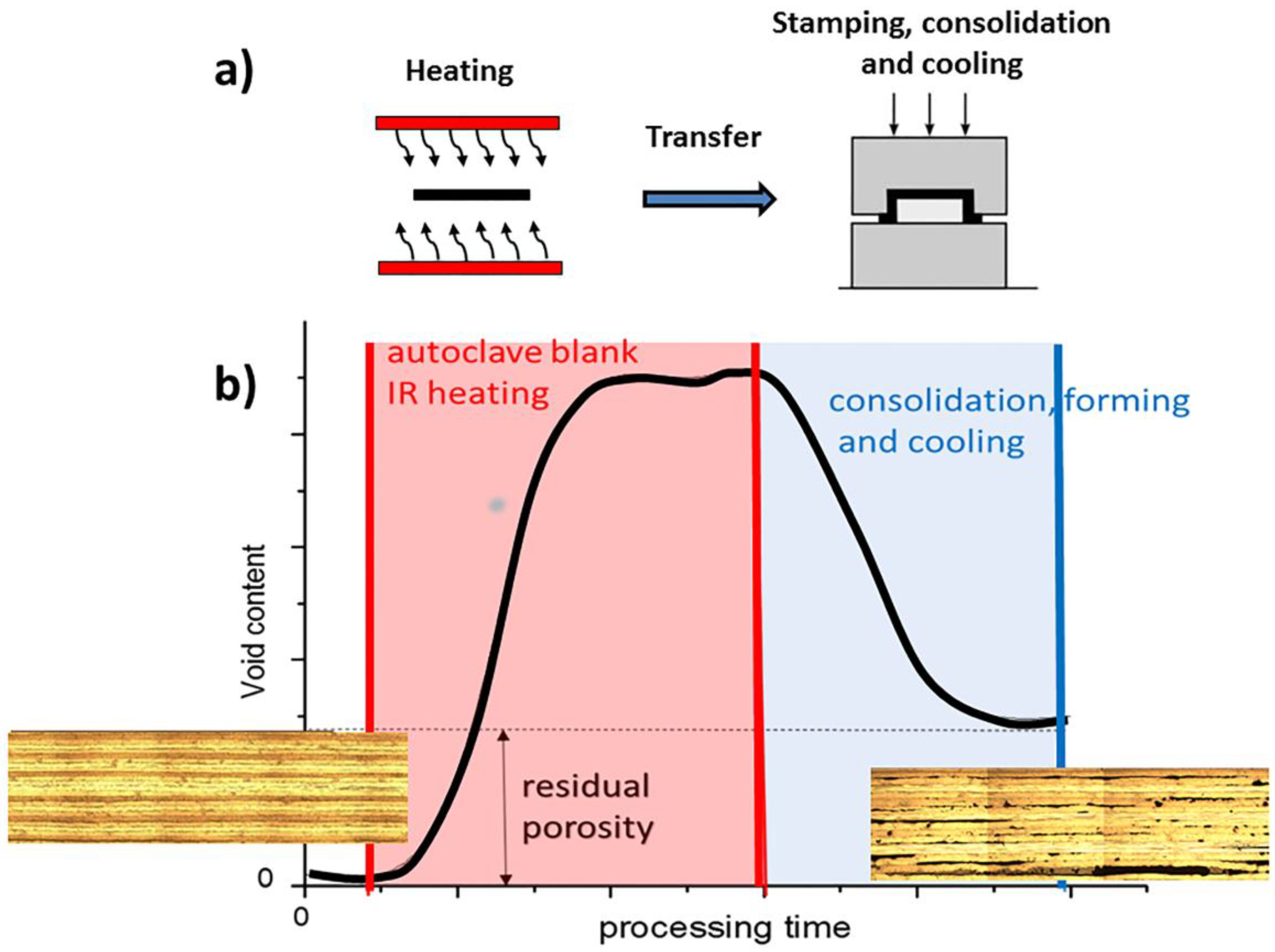
1. Introduction
2. Materials and Methods
2.1. Materials
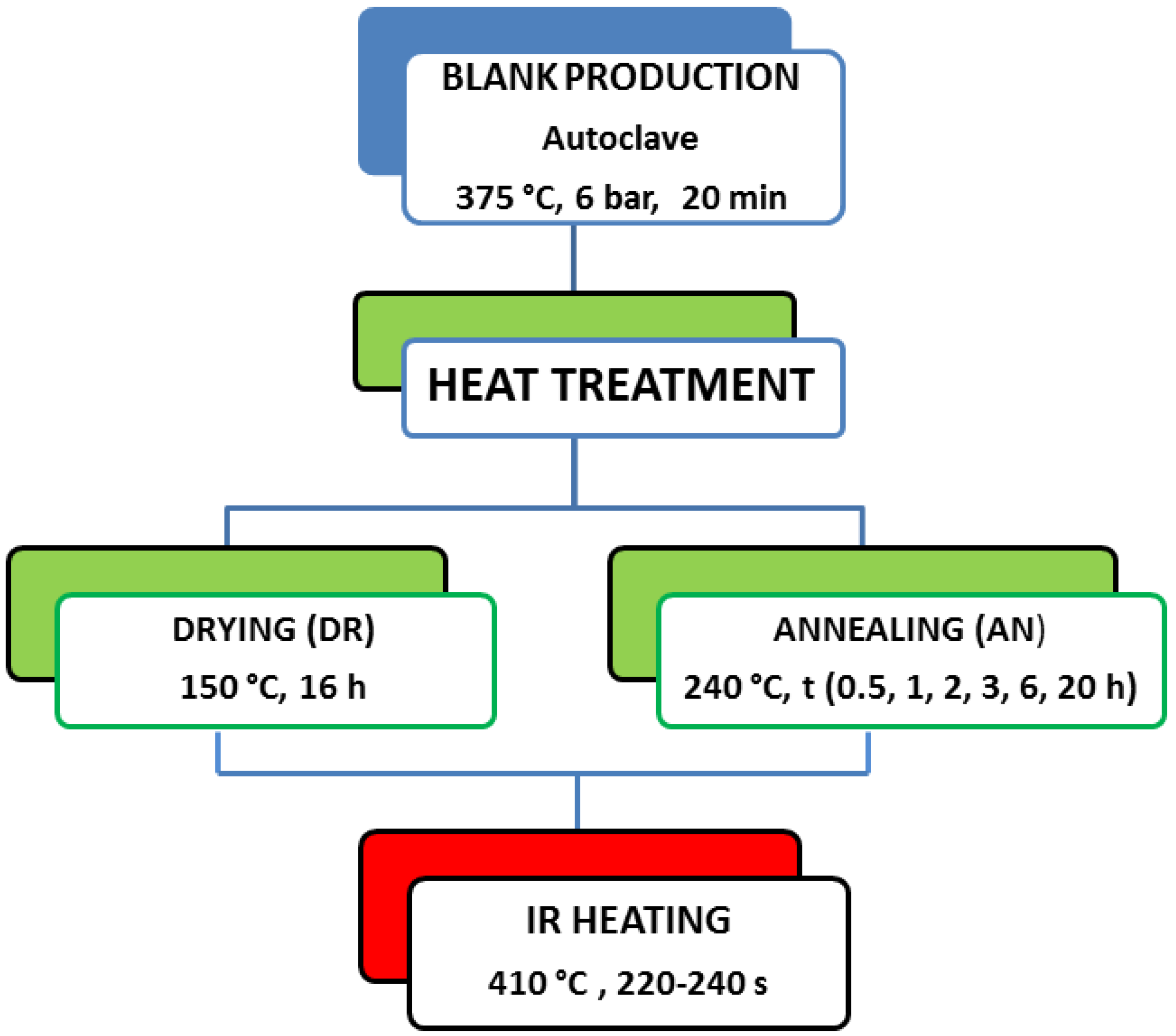
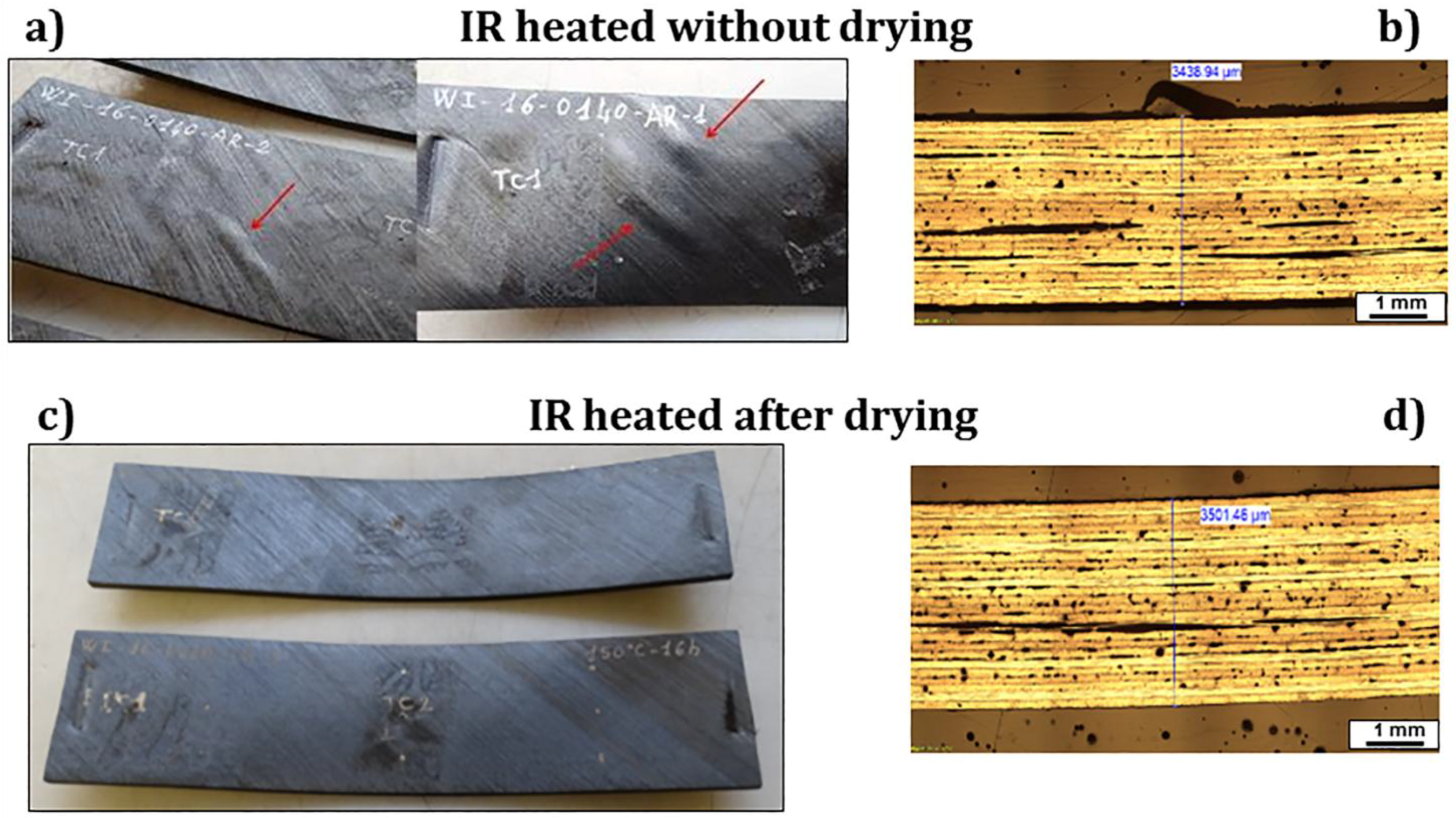
2.2. Sample Preparation and Heat Treatments
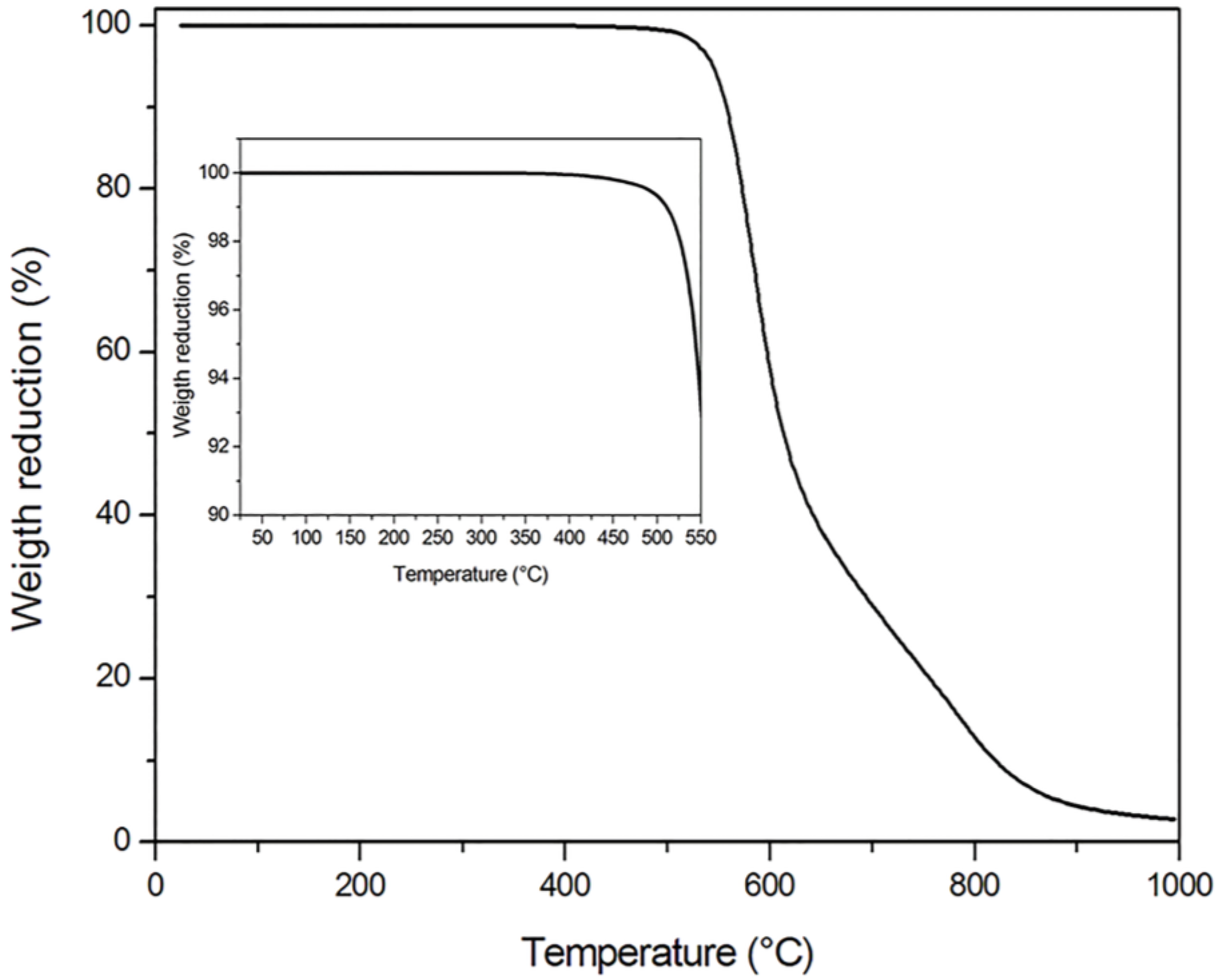
- a drying thermal cycle for 16 h at 150 °C, below Tg, devoted to moisture removal before IR heating;
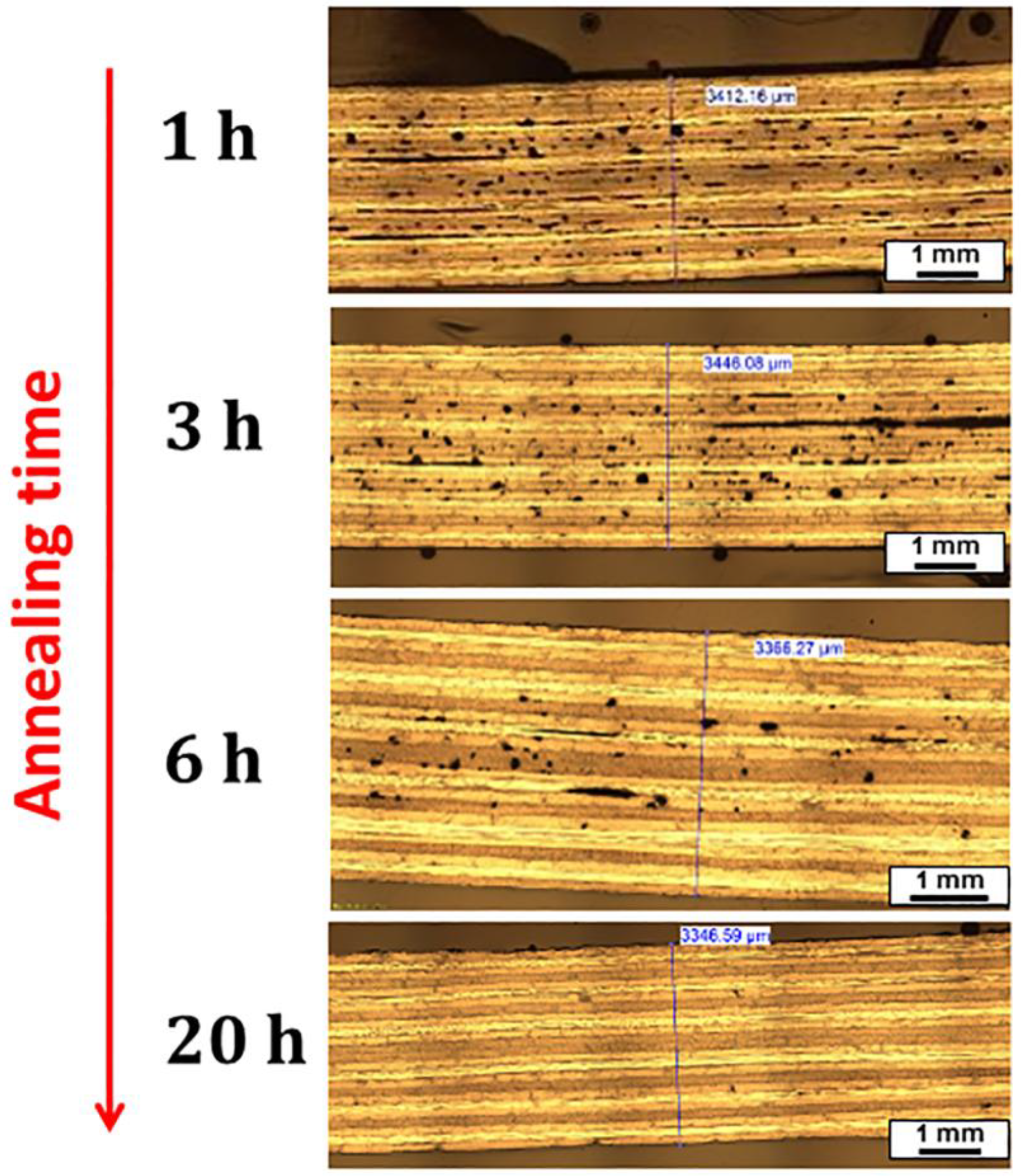
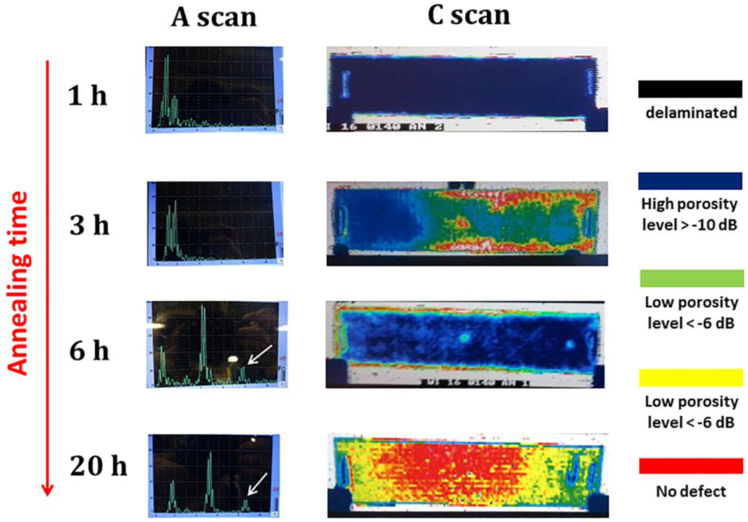
- an annealing for 0.5, 1, 2, 3, 6, and 20 h at 240 °C, at a temperature above Tg in order to promote the relaxation of residual stresses developed during cooling in the autoclave, thanks to the mobility of the amorphous fraction of the matrix.
2.3. Characterization
3. Results
4. Conclusions
Author Contributions
Acknowledgments
Conflicts of Interest
References
- D’Antino, T.; Colombi, P.; Carloni, C.; Sneed, L.H. Estimation of a matrix-fiber interface cohesive material law in FRCM-concrete joints. Compos. Struct. 2018, 193, 103–112. [Google Scholar] [CrossRef]
- Lionetto, F.; Frigione, M. Mechanical and natural durability properties of wood treated with a novel organic preservative/consolidant product. Mater. Des. 2009, 30, 3303–3307. [Google Scholar] [CrossRef]
- Haq, E.U.; Zaidi, S.F.A.; Zubair, M.; Karim, M.R.A.; Padmanabhan, S.K.; Licciulli, A. Hydrophobic silica aerogel glass-fibre composite with higher strength and thermal insulation based on methyltrimethoxysilane (MTMS) precursor. Energy Build. 2017, 151, 494–500. [Google Scholar] [CrossRef]
- Stefanovska, M.; Samakoski, B.; Risteska, S.; Maneski, G. Influence of some technological parameters on the content of voids in composite during on-line consolidation with filament winding technology. Int. J. Chem. Nucl. Mater. Metall. Eng. 2014, 8, 398–402. [Google Scholar]
- Lionetto, F.; Frigione, M. Effect of novel consolidants on mechanical and absorption properties of deteriorated wood by insect attack. J. Cult. Herit. 2012, 13, 195–203. [Google Scholar] [CrossRef]
- Lionetto, F.; Dell’Anna, R.; Montagna, F.; Maffezzoli, A. Modeling of continuous ultrasonic impregnation and consolidation of thermoplastic matrix composites. Compos. Part A Appl. Sci. Manuf. 2016, 82, 119–129. [Google Scholar] [CrossRef]
- Miller, W.S.; Zhuang, L.; Bottema, J.; Wittebrood, A.; De Smet, P.; Haszler, A.; Vieregge, A. Recent development in aluminium alloys for the automotive industry. Mater. Sci. Eng. A 2000, 280, 37–49. [Google Scholar] [CrossRef]
- Lionetto, F.; Moscatello, A.; Maffezzoli, A. Effect of binder powders added to carbon fiber reinforcements on the chemoreology of an epoxy resin for composites. Compos. Part B Eng. 2017, 112, 243–250. [Google Scholar] [CrossRef]
- Offringa, A. Thermoplastics in aerospace, new products through innovative technology. SAMPE J. 2005, 41, 19–27. [Google Scholar]
- Dell’Anna, R.; Lionetto, F.; Montagna, F.; Maffezzoli, A. Lay-Up and Consolidation of a Composite Pipe by In Situ Ultrasonic Welding of a Thermoplastic Matrix Composite Tape. Materials 2018, 11, 786. [Google Scholar] [CrossRef] [PubMed]
- Lionetto, F.; Morillas, M.N.; Pappadà, S.; Buccoliero, G.; Villegas, I.F.; Maffezzoli, A. Hybrid welding of carbon-fiber reinforced epoxy based composites. Compos. Part A Appl. Sci. Manuf. 2018, 104, 32–40. [Google Scholar] [CrossRef]
- Wong, J.C.H.; Blanco, J.M.; Ermanni, P. Filament winding of aramid/PA6 commingled yarns with in situ consolidation. J. Thermoplast. Compos. Mater. 2018, 31, 465–482. [Google Scholar] [CrossRef]
- Lionetto, F.; Mele, C.; Leo, P.; D’Ostuni, S.; Balle, F.; Maffezzoli, A. Ultrasonic spot welding of carbon fiber reinforced epoxy composites to aluminum: Mechanical and electrochemical characterization. Compos. Part B Eng. 2018, 144, 134–142. [Google Scholar] [CrossRef]
- Lionetto, F.; Pappadà, S.; Buccoliero, G.; Maffezzoli, A. Finite element modeling of continuous induction welding of thermoplastic matrix composites. Mater. Des. 2017, 120, 212–221. [Google Scholar] [CrossRef]
- McCool, R.; Murphy, A.; Wilson, R.; Jiang, Z.; Price, M.; Butterfield, J.; Hornsby, P. Thermoforming carbon fibre-reinforced thermoplastic composites. Proc. Inst. Mech. Eng. Part L J. Mater. Des. Appl. 2012, 226, 91–102. [Google Scholar] [CrossRef]
- Benkaddour, A.; Lebrun, G.; Laberge-Lebel, L. Thermostamping of [0/90]n carbon/peek laminates: Influence of support configuration and demolding temperature on part consolidation. Polym. Compos. 2017. [Google Scholar] [CrossRef]
- Salomi, A.; Garstka, T.; Potter, K.; Greco, A.; Maffezzoli, A. Spring-in angle as molding distortion for thermoplastic matrix composite. Compos. Sci. Technol. 2008, 68, 3047–3054. [Google Scholar] [CrossRef]
- Lessard, H.; Lebrun, G.; Benkaddour, A.; Pham, X.-T. Influence of process parameters on the thermostamping of a [0/90]12 carbon/polyether ether ketone laminate. Compos. Part A Appl. Sci. Manuf. 2015, 70, 59–68. [Google Scholar] [CrossRef]
- Parlevliet, P.P.; Bersee, H.E.N.; Beukers, A. Residual stresses in thermoplastic composites—A study of the literature—Part I: Formation of residual stresses. Compos. Part A Appl. Sci. Manuf. 2006, 37, 1847–1857. [Google Scholar] [CrossRef]
- Parlevliet, P.P.; Bersee, H.E.N.; Beukers, A. Residual stresses in thermoplastic composites—A study of the literature. Part III: Effects of thermal residual stresses. Compos. Part A Appl. Sci. Manuf. 2007, 38, 1581–1596. [Google Scholar] [CrossRef]
- Slange, T.K.; Warnet, L.L.; Grouve, W.J.B.; Akkerman, R. Consolidation quality and mechanical performance of stamp formed tailored blanks produced by rapid AFP. In Proceedings of the 21st International ESAFORM Conference on Material Forming, ESAFORM 2018, AIP Conference Proceedings, Palermo, Italy, 23–25 April 2018; AIP Publishing: Melville, NY, USA, 2018; Volume 1960, p. 20031. [Google Scholar]
- Vieille, B.; Albouy, W.; Chevalier, L.; Taleb, L. About the influence of stamping on thermoplastic-based composites for aeronautical applications. Compos. Part B Eng. 2013, 45, 821–834. [Google Scholar] [CrossRef]
- Wakeman, M.D.; Blanchard, P.; Månson, J.A.E. Void evolution during stamp-forming of thermoplastic composites. In Proceedings of the 15th International Conference on Composite Materials, Durban, South Africa, 27 June–1 July 2005. [Google Scholar]
- Xueshu, L.I.U.; Fei, C. A review of void formation and its effects on the mechanical performance of carbon fiber reinforced plastic. Eng. Trans. 2016, 64, 33–51. [Google Scholar]
- Solvay APC (PEKK-FC) Datasheet. 2017, pp. 1–5. Available online: https://www.cytec.com/sites/default/files/datasheets/APC-PEKK-FC_CM_EN.pdf (accessed on 29 May 2018).
- Jones, R.M. Mechanics of Composite Materials; Scripta Book Company: Washington, DC, USA, 1975; Volume 193. [Google Scholar]
- Pappadà, S.; Salomi, A.; Montanaro, J.; Passaro, A.; Caruso, A.; Maffezzoli, A. Fabrication of a thermoplastic matrix composite stiffened panel by induction welding. Aerosp. Sci. Technol. 2015, 43, 314–320. [Google Scholar] [CrossRef]
- Casavola, C.; Palano, F.; De Cillis, F.; Tati, A.; Terzi, R.; Luprano, V. Analysis of CFRP Joints by Means of T-Pull Mechanical Test and Ultrasonic Defects Detection. Materials 2018, 11, 620. [Google Scholar] [CrossRef] [PubMed]


| Samples | Stacking Sequence | Nominal Thickness (mm) | Characterization Methods |
|---|---|---|---|
| Quasi-isotropic (QI) blanks | [−45, 90, 45, 0]3s | 3.3 | TGA NDE Thickness |
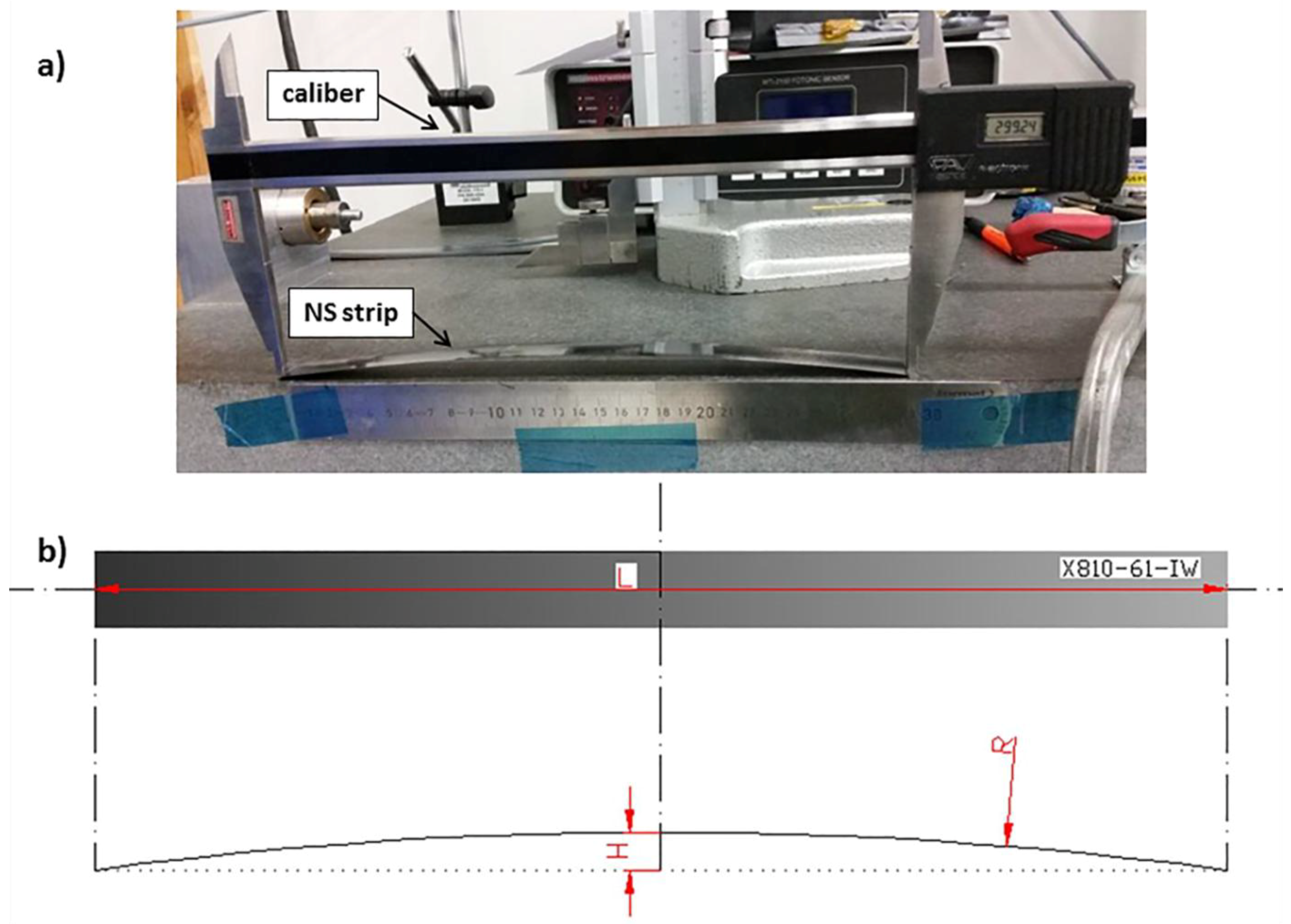
| Non-symmetric (NS) strips | [0, 0, 90] | 0.4 | Curvature measurement |
| Non-Symmetric (NS) Strips [0, 0, 90] | L (mm) | H (mm) | R (mm) |
|---|---|---|---|
| Before Annealing | 298.72 | 8.04 | 1391.35 |
| After Annealing | 299.23 | 2.16 | 5182.71 |
| Annealing Time at 240 °C (h) | Average Thickness Change (%) |
|---|---|
| 0 | 7.67 |
| 0.5 | 6.15 |
| 1 | 5.35 |
| 2 | 2.67 |
| 3 | 1.63 |
| 6 | 0.83 |
| 20 | 0.45 |
© 2018 by the authors. Licensee MDPI, Basel, Switzerland. This article is an open access article distributed under the terms and conditions of the Creative Commons Attribution (CC BY) license (http://creativecommons.org/licenses/by/4.0/).
Share and Cite
Donadei, V.; Lionetto, F.; Wielandt, M.; Offringa, A.; Maffezzoli, A. Effects of Blank Quality on Press-Formed PEKK/Carbon Composite Parts. Materials 2018, 11, 1063. https://doi.org/10.3390/ma11071063
Donadei V, Lionetto F, Wielandt M, Offringa A, Maffezzoli A. Effects of Blank Quality on Press-Formed PEKK/Carbon Composite Parts. Materials. 2018; 11(7):1063. https://doi.org/10.3390/ma11071063
Chicago/Turabian StyleDonadei, Valentina, Francesca Lionetto, Michael Wielandt, Arnt Offringa, and Alfonso Maffezzoli. 2018. "Effects of Blank Quality on Press-Formed PEKK/Carbon Composite Parts" Materials 11, no. 7: 1063. https://doi.org/10.3390/ma11071063
APA StyleDonadei, V., Lionetto, F., Wielandt, M., Offringa, A., & Maffezzoli, A. (2018). Effects of Blank Quality on Press-Formed PEKK/Carbon Composite Parts. Materials, 11(7), 1063. https://doi.org/10.3390/ma11071063