An Alternative Lifetime Model for White Light Emitting Diodes under Thermal–Electrical Stresses


Abstract
1. Introduction
2. The Lifetime Model for LEDs under Thermal and Electrical Stresses
3. Solution and Analysis of the Lifetime Model
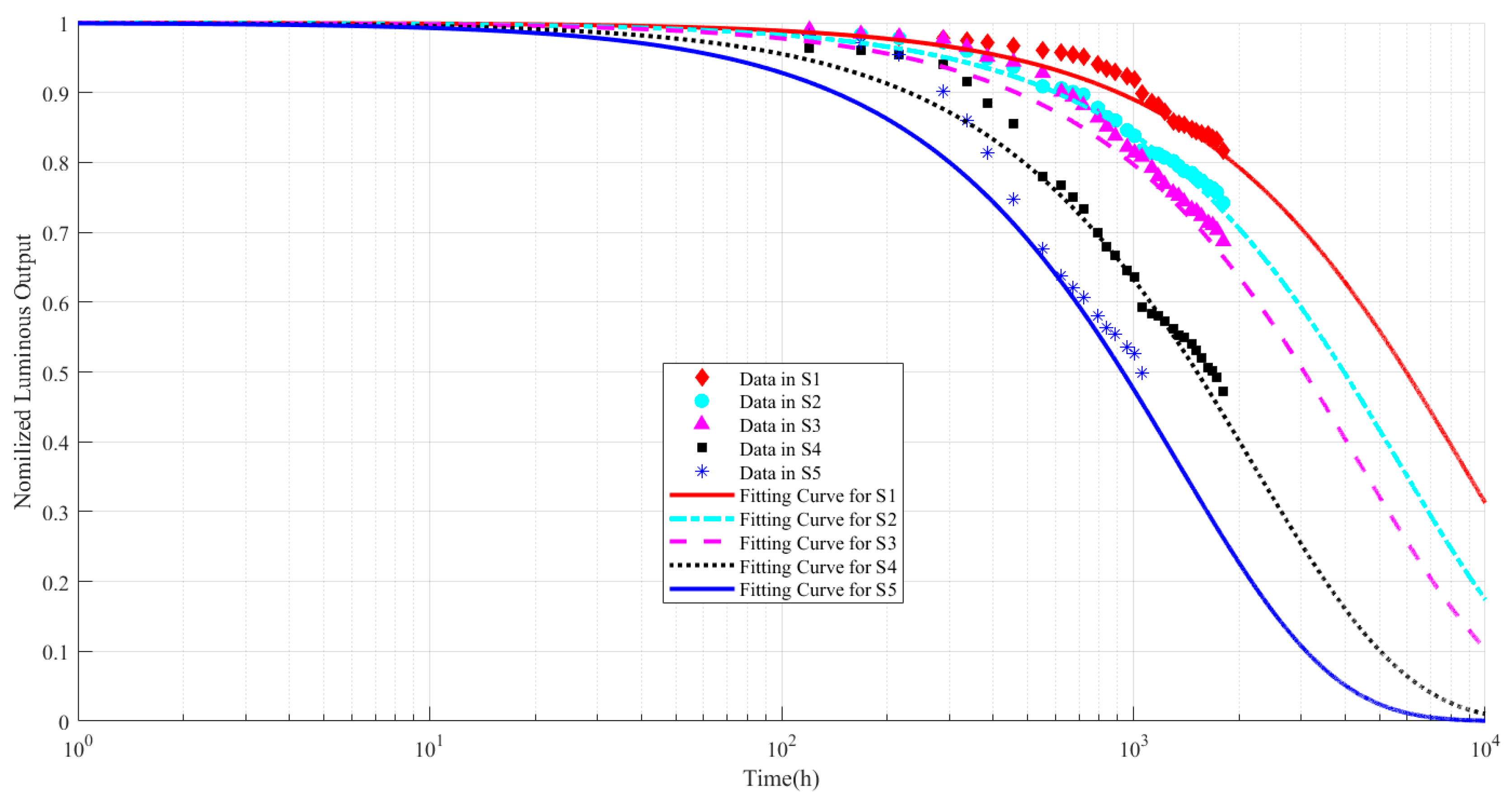
3.1. Model Solving
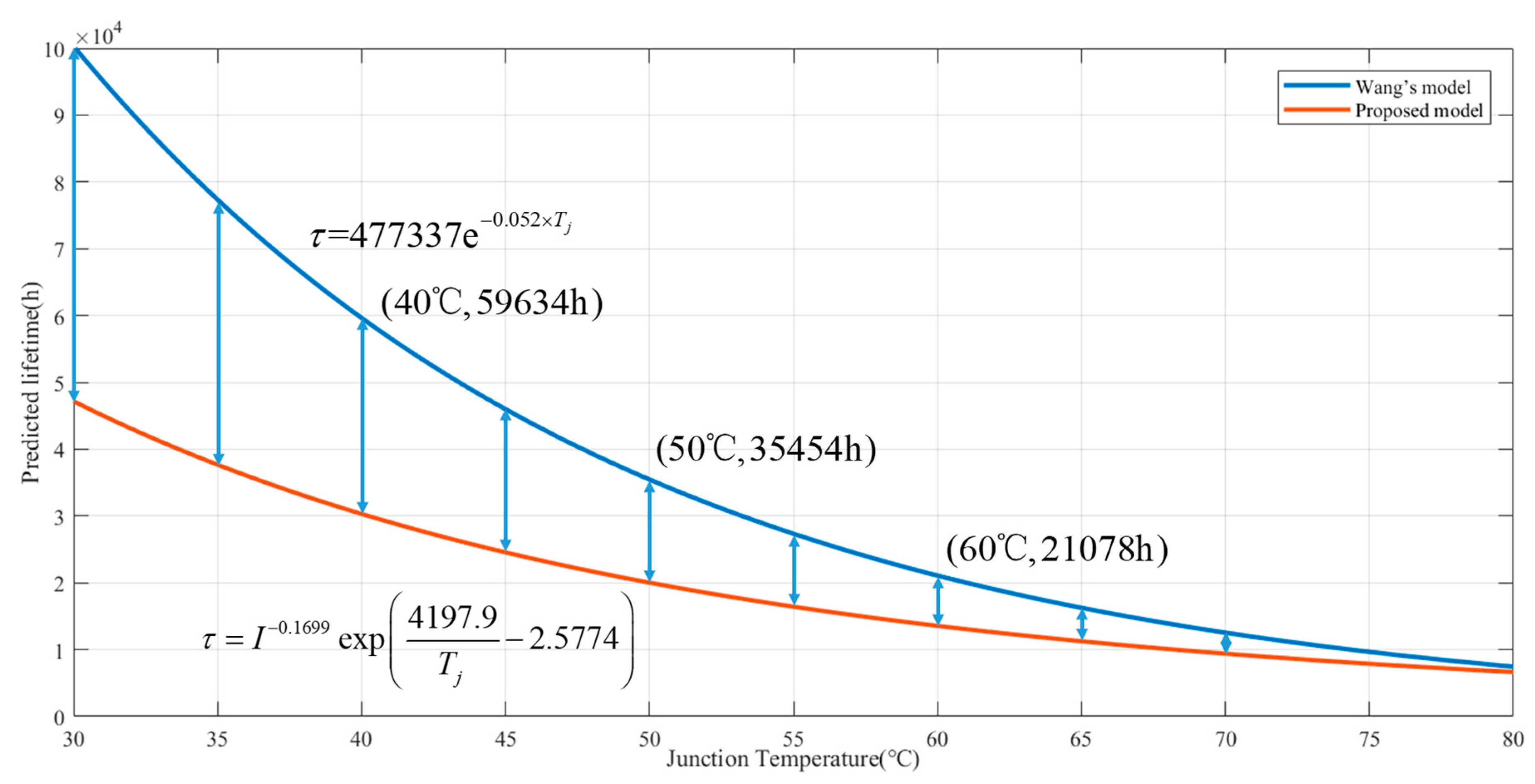
3.2. Compare with Wang’s Model
3.3. Effects of Junction Temperature and Driving Current on Lifetime
4. Applications and Case Study of the Lifetime Model
5. Conclusions
Author Contributions
Funding
Acknowledgments
Conflicts of Interest
Nomenclature
| Lumen maintenance | |
| Pre-factor of LED’s depreciation | |
| Degradation rate of LEDs | |
| Failure criterion of LEDs | |
| Junction temperature in LEDs | |
| Driving current | |
| LED’s activation energy | |
| Boltzmann constant | |
| Model constant | |
| Model constant |
References
- Van Driel, W.D.; Fan, X.J. Solid State Lighting Reliability: Components to Systems; Springer: New York, NY, USA, 2012. [Google Scholar]
- Chang, M.H.; Das, D.; Varde, P.V.; Pecht, M. Light emitting diodes reliability review. Microelectron. Reliab. 2012, 52, 762–782. [Google Scholar] [CrossRef]
- Qian, C.; Fan, J.J.; Fang, J.; Yu, C.; Ren, Y.; Fan, X.J.; Zhang, G.Q. Photometric and colorimetric assessment of LED chip scale packages by using a step-stress accelerated degradation test (SSADT) method. Materials 2017, 10, 1181. [Google Scholar] [CrossRef] [PubMed]
- Fan, J.J.; Qian, C.; Yung, K.C.; Fan, X.J.; Zhang, G.Q.; Pecht, M. Optimal design of life testing for high-brightness white LEDs using the six sigma DMAIC approach. IEEE Trans. Device Mater. Reliab. 2015, 15, 576–587. [Google Scholar] [CrossRef]
- Sun, B.; Jiang, X.P.; Yung, K.-C.; Fan, J.J.; Pecht, M. A review of prognostics techniques for high-power white LEDs. IEEE Trans. Power Electron. 2017, 32, 6338–6362. [Google Scholar] [CrossRef]
- IES-LM-80-08 Approved Method for Lumen Maintenance Testing of LED Light Source; Illuminating Engineering Society: New York, NY, USA, 2008.
- IES-TM-21-11 Projecting Long Term Lumen Maintenance of LED Light Sources; Illuminating Engineering Society: New York, NY, USA, 2011.
- Huang, J.L.; Golubović, D.S.; Koh, S.; Yang, D.G.; Li, X.P.; Fan, X.J.; Zhang, G.Q. Degradation modeling of mid-power white-light LEDs by using Wiener process. Opt. Express 2015, 23, A966–A978. [Google Scholar] [CrossRef] [PubMed]
- Fan, J.J.; Yung, K.C.; Pecht, M. Lifetime estimation of high-power white LED using degradation-data-driven method. IEEE Trans. Device Mater. Reliab. 2012, 12, 470–477. [Google Scholar] [CrossRef]
- Tao, X.H.; Hui, S.Y.R. Dynamic photoelectrothermal theory for light-emitting diode systems. IEEE Trans. Ind. Electron. 2012, 59, 1751–1759. [Google Scholar] [CrossRef]
- Hui, S.Y.R.; Chen, H.; Tao, X.H. An Extended photoelectrothermal theory for LED systems: A tutorial from device characteristic to system design for general lighting. IEEE Trans. Power Electron. 2012, 27, 4571–4583. [Google Scholar] [CrossRef]
- Hui, S.Y.R.; Qin, Y.X. A General photo-electro-thermal theory for light emitting diode (LED) systems. IEEE Trans. Power Electron. 2009, 24, 1967–1976. [Google Scholar] [CrossRef]
- Watzke, S.; Altieri-Weimar, P. Degradation of silicone in white LEDs during device operation: A finite element approach to product reliability prediction. Microelectron. Reliab. 2015, 55, 733–737. [Google Scholar] [CrossRef]
- Fischer, H.R.; Semprimoschnig, C.; Mooney, C.; Rohr, T.; van Eck, E.R.H.; Verkuijlen, M.H.W. Degradation mechanism of silicone glues under UV irradiation and options for designing materials with increased stability. Polym. Degrad. Stabil. 2013, 98, 720–726. [Google Scholar] [CrossRef]
- Sun, B.; Fan, X.J.; Ye, H.Y.; Fan, J.J.; Qian, C.; Van Driel, W.D.; Zhang, G.Q. A novel lifetime prediction for integrated LED lamps by electronic-thermal simulation. Reliab. Eng. Syst. Saf. 2017, 163, 14–21. [Google Scholar] [CrossRef]
- Huang, J.; Golubovic, D.S.; Koh, S.; Yang, D.; Li, X.; Fan, X.; Zhang, G.Q. Lumen degradation modeling of white-light LEDs in step stress accelerated degradation test. Reliab. Eng. Syst. Saf. 2016, 154, 152–159. [Google Scholar] [CrossRef]
- Han, D. Time and cost constrained optimal designs of constant-stress and step-stress accelerated life tests. Reliab. Eng. Syst. Saf. 2015, 140, 1–14. [Google Scholar] [CrossRef]
- Benavides, E.M. Reliability Model for step-stress and variable-stress situations. IEEE Trans. Reliab. 2011, 60, 219–233. [Google Scholar] [CrossRef]
- Hamon, B.; van Driel, W.D. LED degradation: From component to system. Microelectron. Reliab. 2016, 64, 599–604. [Google Scholar] [CrossRef]
- Mehr, M.Y.; Van Driel, W.D.; Zhang, G.Q. Reliability and lifetime prediction of remote phosphor plates in solid-state lighting applications using accelerated degradation testing. J. Electron. Mater. 2016, 45, 444–452. [Google Scholar] [CrossRef]
- Qian, C.; Fan, X.J.; Fan, J.J.; Yuan, C.A.; Zhang, G.Q. An accelerated test method of luminous flux depreciation for LED luminaires and lamps. Reliab. Eng. Syst. Saf. 2016, 147, 84–92. [Google Scholar] [CrossRef]
- Trevisanello, L.; Meneghini, M.; Mura, G.; Vanzi, M.; Pavesi, M.; Meneghesso, G.; Zanoni, E. Accelerated life test of high brightness light emitting diodes. IEEE Trans. Device Mater. Reliab. 2008, 8, 304–311. [Google Scholar] [CrossRef]
- Luo, X.B.; Wu, B.L.; Liu, S. Effects of moist environments on LED module reliability. IEEE Trans. Device Mater. Reliab. 2010, 10, 182–186. [Google Scholar] [CrossRef]
- Yanagisawa, T.; Kojima, T. Long-term accelerated current operation of white light-emitting diodes. J. Lumines. 2005, 114, 39–42. [Google Scholar] [CrossRef]
- Huang, J.; Golubović, D.S.; Koh, S.; Yang, D.; Li, X.; Fan, X.J.; Zhang, G.Q. Rapid degradation of mid-power white-light LEDs in saturated moisture conditions. IEEE Trans. Device Mater. Reliab. 2015, 15, 478–485. [Google Scholar] [CrossRef]
- Huang, J.; Golubović, D.S.; Koh, S.; Yang, D.; Li, X.; Fan, X.J.; Zhang, G.Q. Degradation mechanisms of mid-power white-light LEDs under high-temperature–humidity conditions. IEEE Trans. Device Mater. Reliab. 2015, 15, 220–228. [Google Scholar] [CrossRef]
- Vázquez, M.; Núñez, N.; Nogueira, E.; Borreguero, A. Degradation of AlInGaP red LEDs under drive current and temperature accelerated life tests. Microelectron. Reliab. 2010, 50, 1559–1562. [Google Scholar] [CrossRef]
- Edirisinghe, M.; Rathnayake, P. Arrhenius accelerated life test for luminary life of high bright light emitting diodes. Int. Lett. Chem. Phys. Astron. 2015, 49, 48–59. [Google Scholar] [CrossRef]
- Yang, Y.H.; Su, Y.F.; Chiang, K.N. Acceleration factor analysis of aging test on gallium nitride (GaN)-based high power light-emitting diode (LED). In Proceedings of the Thermal and Thermomechanical Phenomena in Electronic Systems (ITherm), Orlando, FL, USA, 27–30 May 2014. [Google Scholar]
- Koh, S.; Yuan, C.; Sun, B.; Li, B.; Fan, X.J.; Zhang, G.Q. Product level accelerated lifetime test for indoor LED luminaires. In Proceedings of the Thermal, Mechanical and Multi-Physics Simulation and Experiments in Microelectronics and Microsystems (EuroSimE), Wroclaw, Poland, 14–17 April 2013. [Google Scholar]
- Wang, F.K.; Chu, T.P. Lifetime predictions of LED-based light bars by accelerated degradation test. Microelectron. Reliab. 2012, 52, 1332–1336. [Google Scholar] [CrossRef]
- Nogueira, E.; Mateos, J. Accelerated life testing LEDs on temperature and current. In Proceedings of the Electron Devices (CDE), Palma de Mallorca, Spain, 8–11 February 2011. [Google Scholar]
- Liu, L.; Ling, M.; Yang, J.; Xiong, W.; Jia, W.; Wang, G. Efficiency degradation behaviors of current/thermal co-stressed GaN-based blue light emitting diodes with vertical-structure. J. Appl. Phys. 2012, 111, 093110. [Google Scholar] [CrossRef]
- Huang, S.D.; Zhou, L.; Cao, G.Z.; Liu, H.Y.; Hu, Y.M.; Jing, G.; Cao, M.G.; Xiao, W.P.; Liu, Y. A novel multiple-stress-based predictive model of LEDs for rapid lifetime estimation. Microelectron. Reliab. 2017, 78, 46–52. [Google Scholar] [CrossRef]
- Qu, X.; Wang, H.; Zhan, X.; Blaabjerg, F.; Chung, H.S.H. A lifetime prediction method for LEDs considering real mission profiles. IEEE Trans. Power Electron. 2017, 32, 8718–8727. [Google Scholar] [CrossRef]
- Miner, M. Cumulative damage in fatigue. J. Appl. Mech. 1945, 12, A159–A164. [Google Scholar]


| Stress Level | Experimental Conditions (Driving Current, Ambient Temperature) | Quantity of Sample | Junction Temperature Tj ( °C) |
|---|---|---|---|
| S1 | (20 mA, 60 °C) | 15 | 82.4 |
| S2 | (30 mA, 60 °C) | 15 | 93.6 |
| S3 | (25 mA, 72.5 °C) | 15 | 100.5 |
| S4 | (20 mA, 85 °C) | 15 | 107.4 |
| S5 | (30 mA, 85 °C) | 15 | 118.6 |
| Item | Stress Level | ||||
|---|---|---|---|---|---|
| S1 | S2 | S3 | S4 | S5 | |
| Expected lifetime (L50) | 6126.8 h | 3987.7 h | 3329.5 h | 1582.9 h | 1023.2 h |
| Driving current () | 20 mA | 30 mA | 25 mA | 20 mA | 30 mA |
| Junction temperature () | 355.33 K | 366.75 K | 373.65 K | 380.55 K | 391.75 |
| Predicted lifetime | – | – | – | 3038.0 h | 1965.2 h |
| No. | Season | Accumulated Duration | Stress Level (Ta, I) | Predicted Lifetime () |
|---|---|---|---|---|
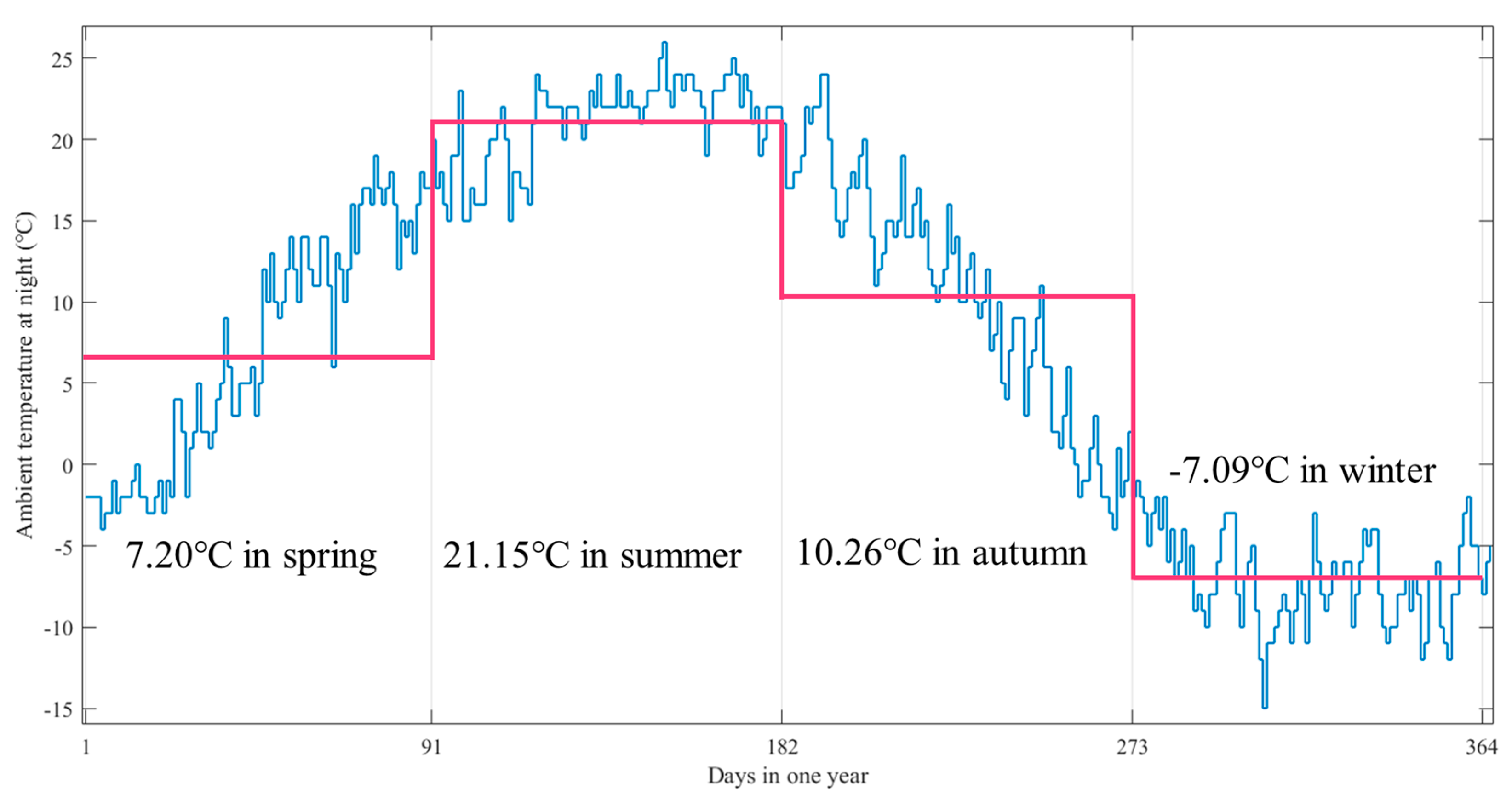
| 1 | Spring | 910 h | (7.20 °C, 20 mA) | 34,201 h |
| 2 | Summer | 910 h | (21.15 °C, 20 mA) | 19,113 h |
| 3 | Autumn | 910 h | (10.26 °C, 20 mA) | 29,969 h |
| 4 | Winter | 910 h | (−7.09 °C, 20 mA) | 65,702 h |
© 2018 by the authors. Licensee MDPI, Basel, Switzerland. This article is an open access article distributed under the terms and conditions of the Creative Commons Attribution (CC BY) license (http://creativecommons.org/licenses/by/4.0/).
Share and Cite
Yang, X.; Sun, B.; Wang, Z.; Qian, C.; Ren, Y.; Yang, D.; Feng, Q. An Alternative Lifetime Model for White Light Emitting Diodes under Thermal–Electrical Stresses. Materials 2018, 11, 817. https://doi.org/10.3390/ma11050817
Yang X, Sun B, Wang Z, Qian C, Ren Y, Yang D, Feng Q. An Alternative Lifetime Model for White Light Emitting Diodes under Thermal–Electrical Stresses. Materials. 2018; 11(5):817. https://doi.org/10.3390/ma11050817
Chicago/Turabian StyleYang, Xi, Bo Sun, Zili Wang, Cheng Qian, Yi Ren, Dezhen Yang, and Qiang Feng. 2018. "An Alternative Lifetime Model for White Light Emitting Diodes under Thermal–Electrical Stresses" Materials 11, no. 5: 817. https://doi.org/10.3390/ma11050817
APA StyleYang, X., Sun, B., Wang, Z., Qian, C., Ren, Y., Yang, D., & Feng, Q. (2018). An Alternative Lifetime Model for White Light Emitting Diodes under Thermal–Electrical Stresses. Materials, 11(5), 817. https://doi.org/10.3390/ma11050817