Strain Behavior of Concrete Panels Subjected to Different Nose Shapes of Projectile Impact


Abstract
1. Introduction
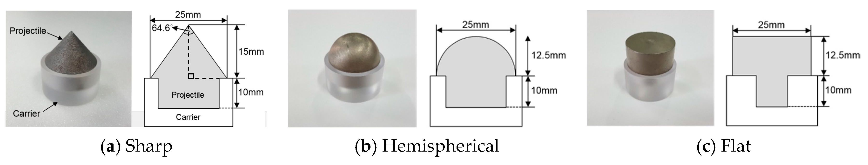
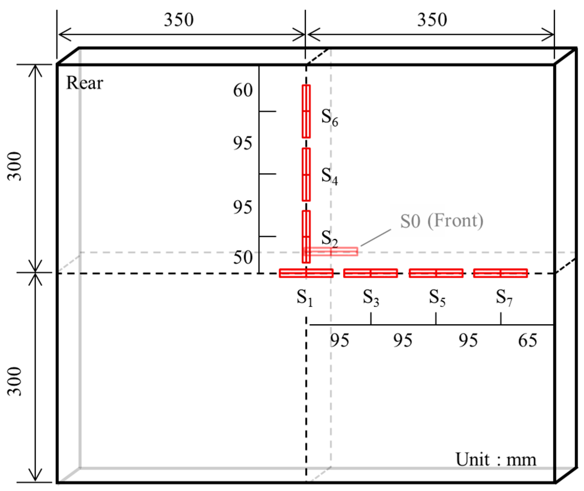
2. Experimental Program
3. Results and Discussion
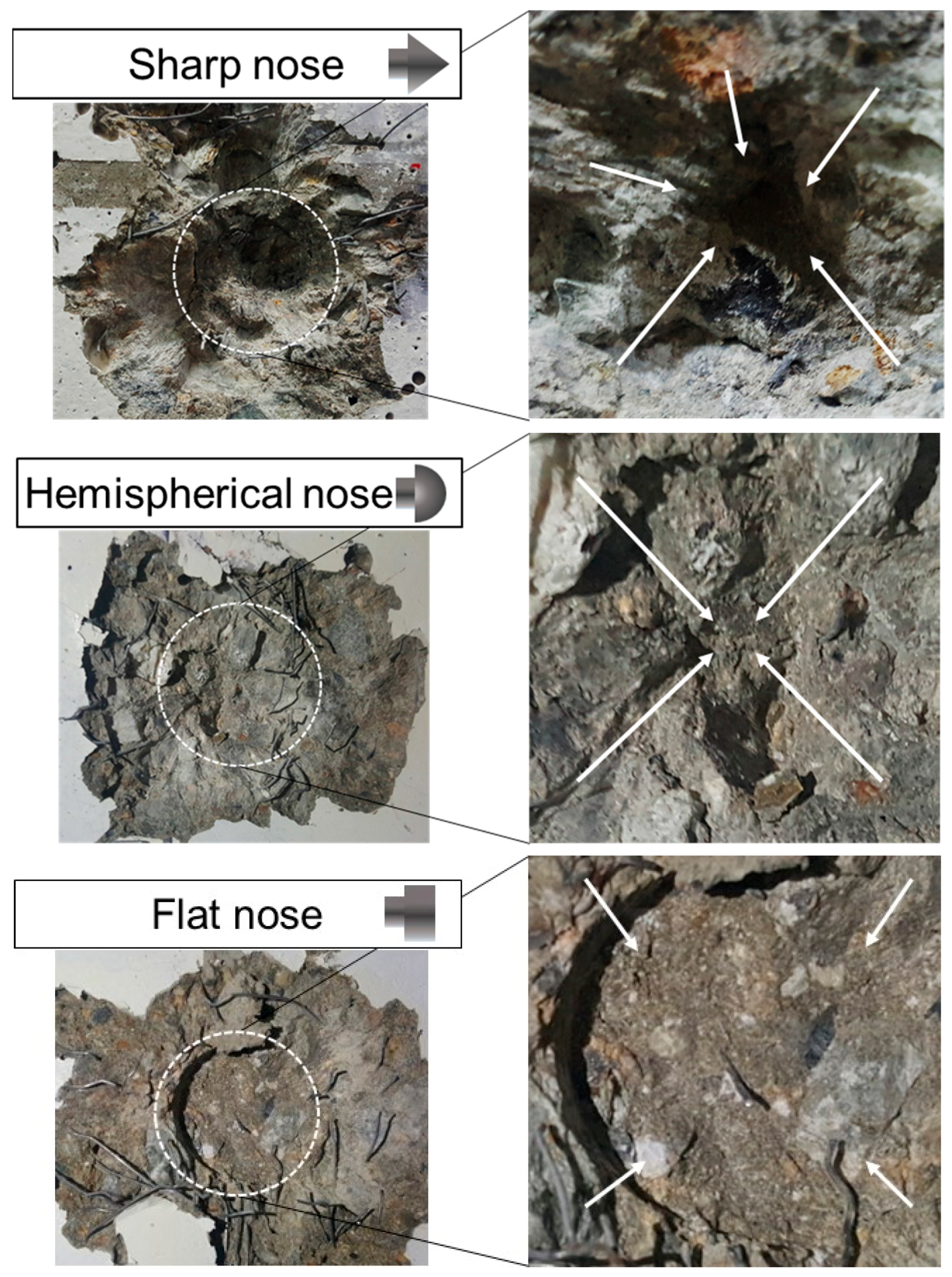
3.1. Appearance of Fracture on Concrete
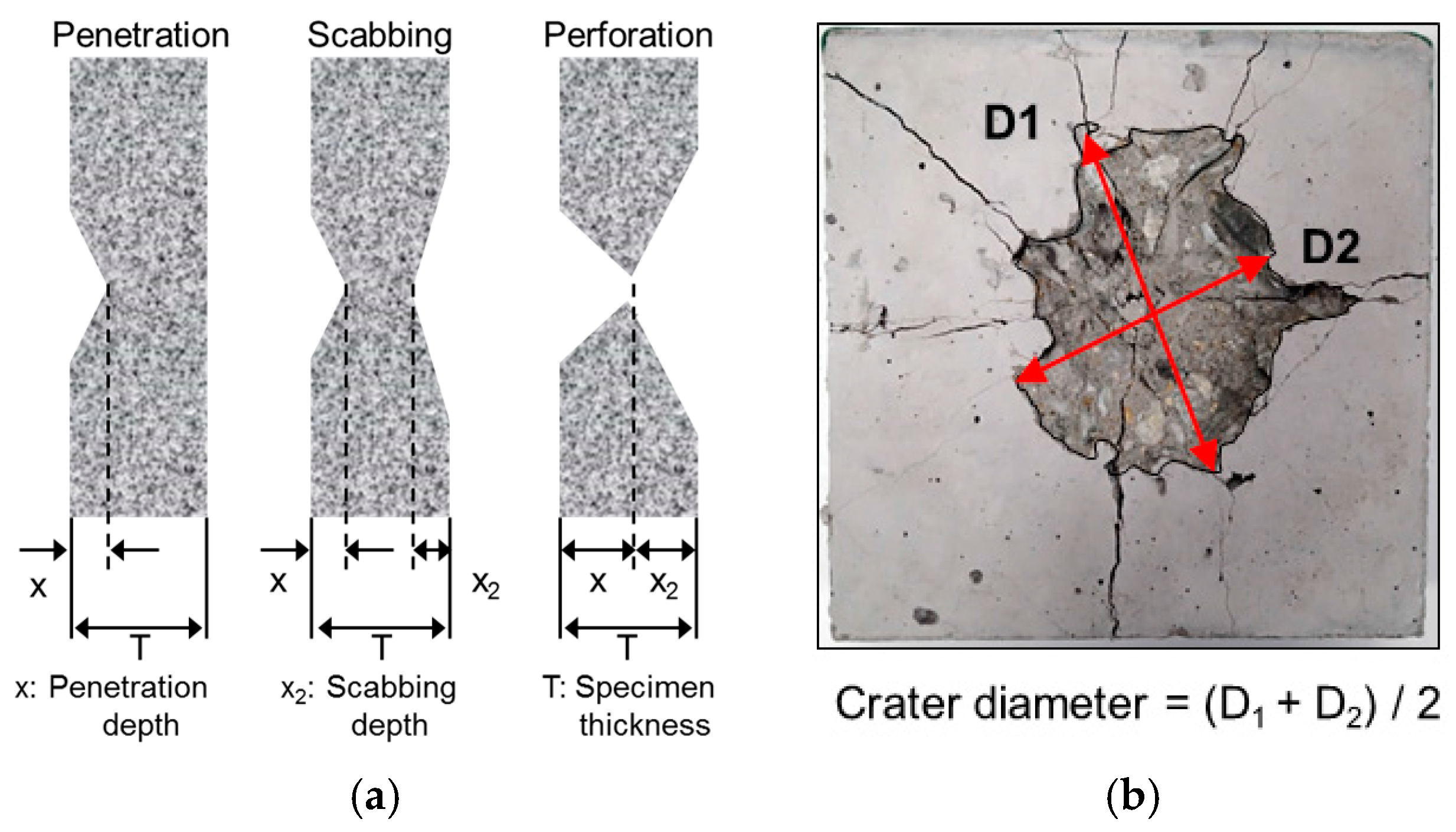
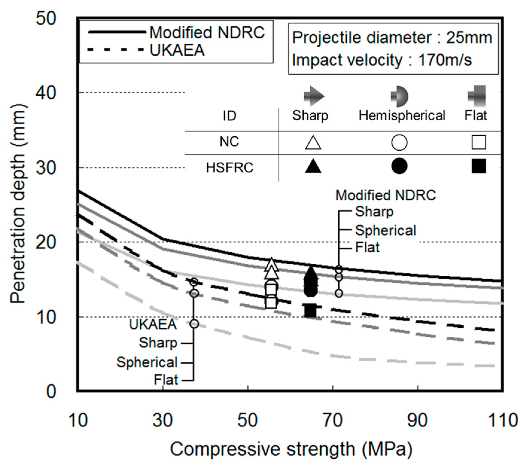
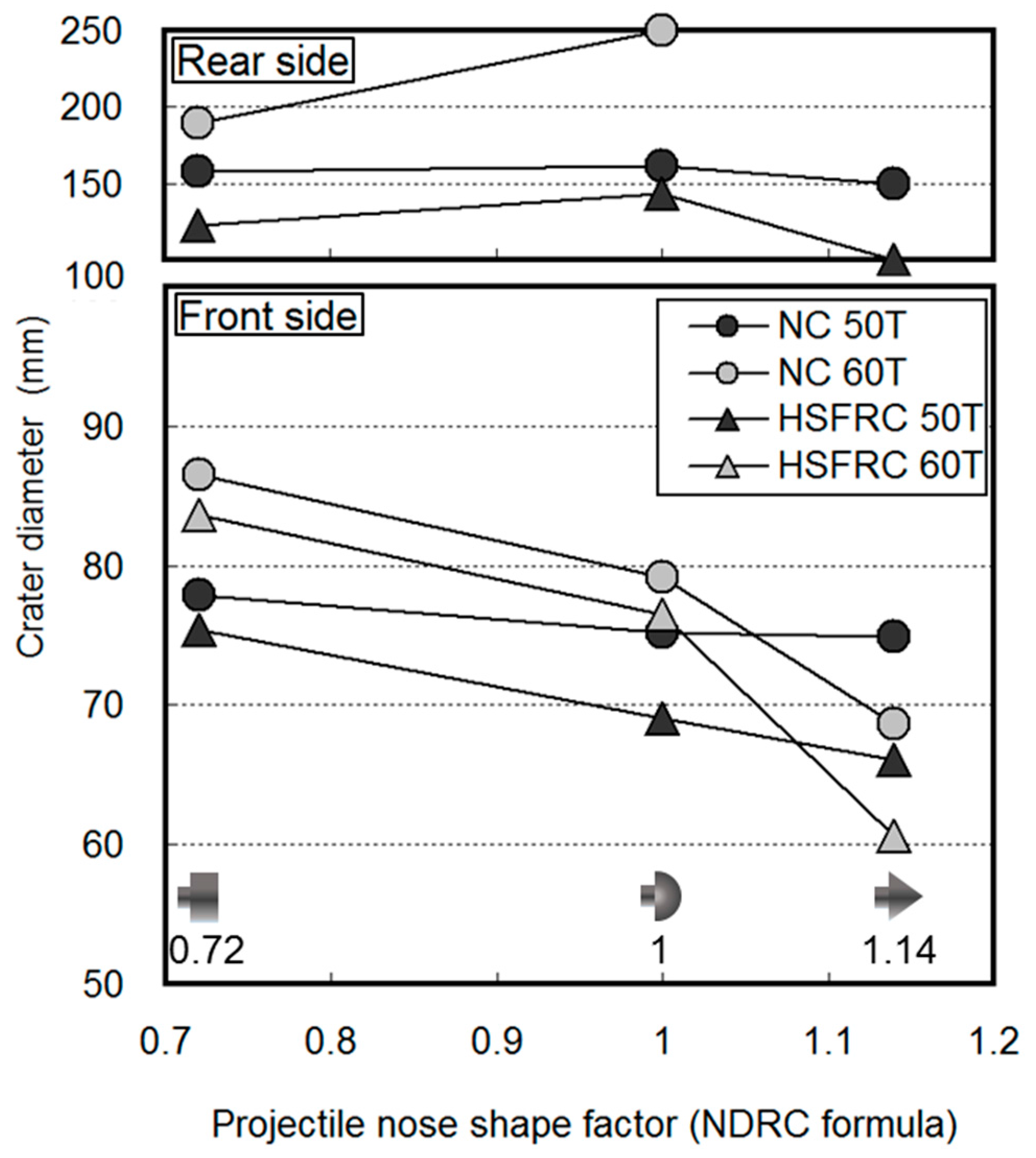
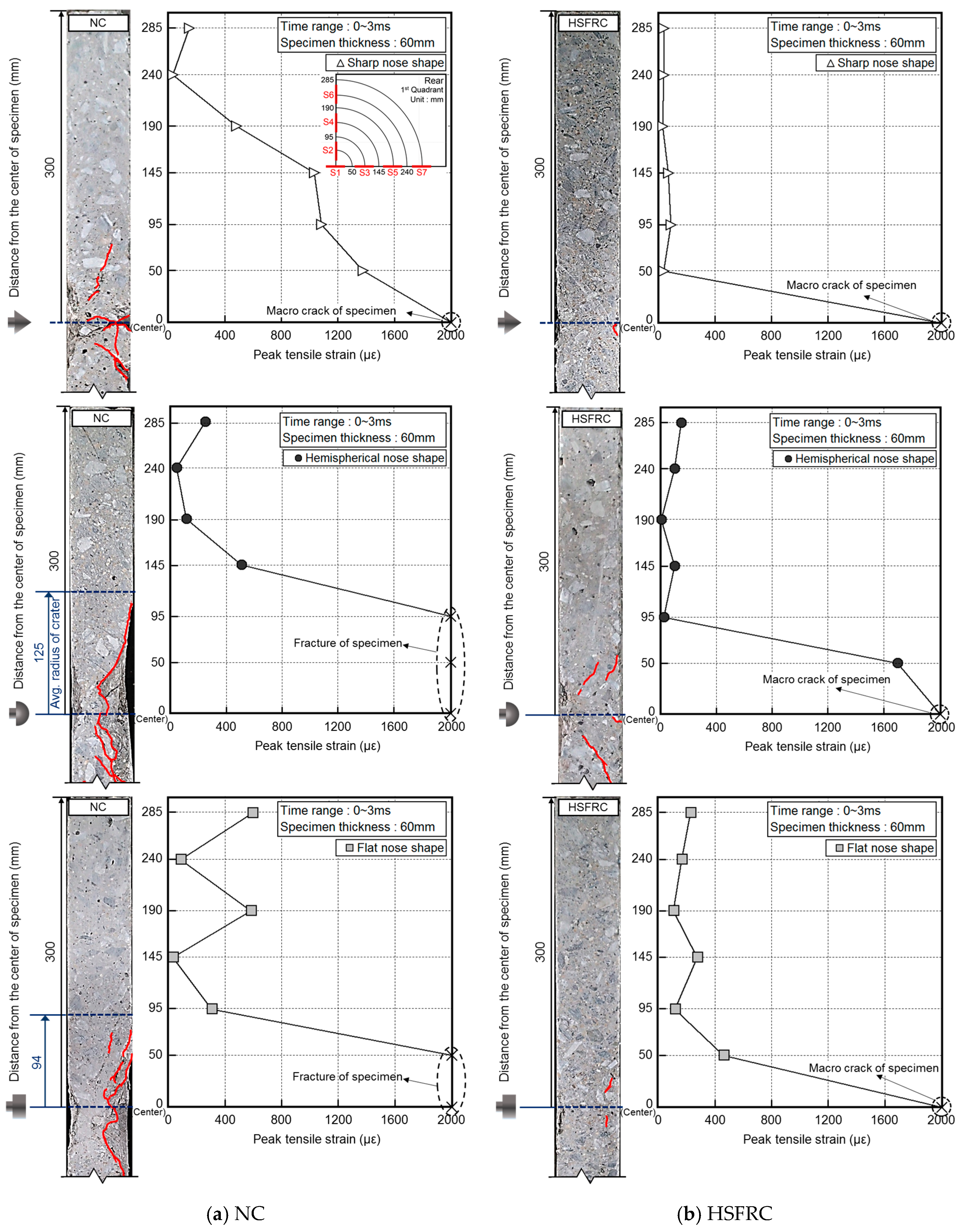
3.2. Fracture Depth and Crater Diameter
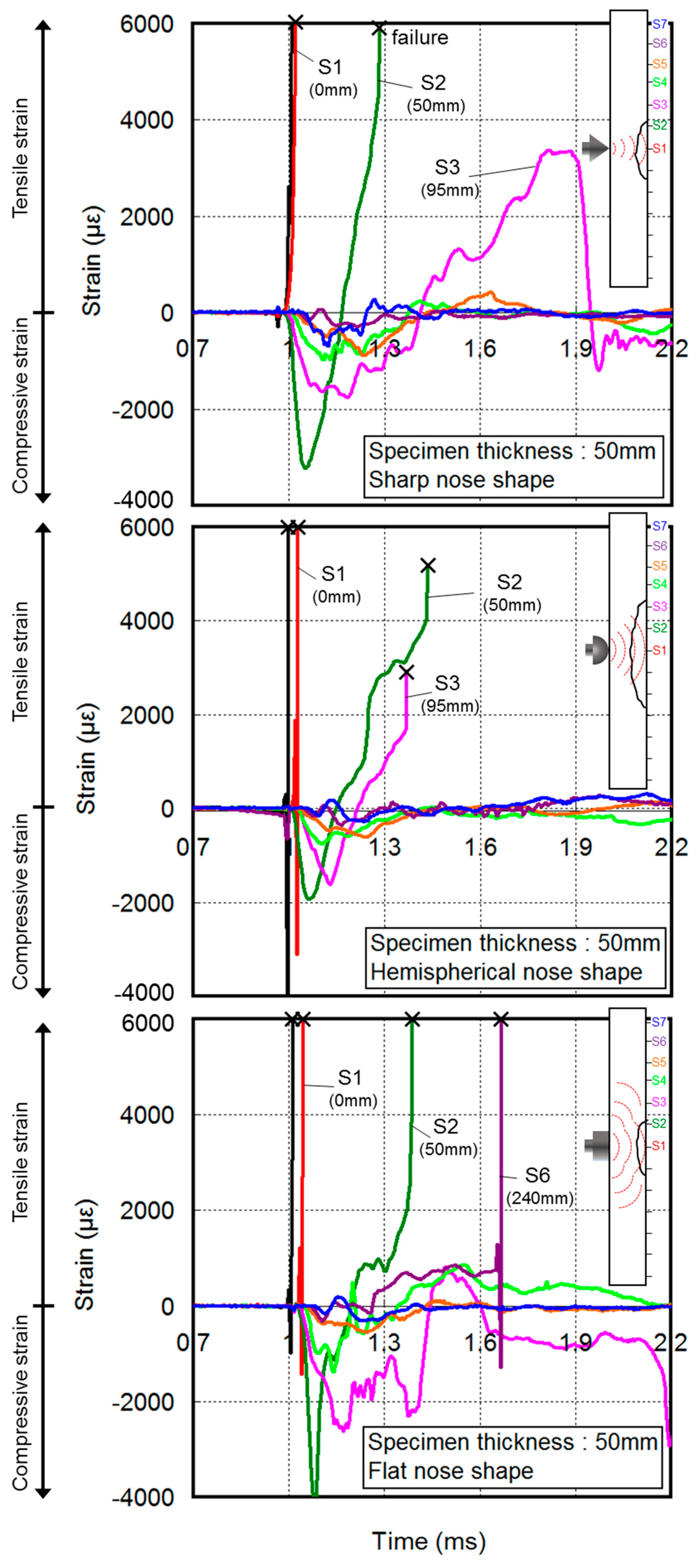
3.3. Rear-Face Strain Behavior
4. Conclusions
- The sharp projectile nose resulted in a deeper penetration than hemispherical and flat projectile nose by up to about 36% because of the concentration of the impact force. Conversely, the flat projectile nose resulted in shallower penetrations because of the distribution of the impact force. In addition, the scabbing depth and crater diameter on the rear face of the concrete were larger for hemispherical projectile impact than for other projectiles. Therefore, if the scabbing occurs in concrete due to projectile impact, it is expected that the amount of the fragment by hemispherical projectiles will be greatest.
- The tensile strain on the rear face obtained from the experimental result was widely distributed as the projectile nose shape became blunter. The strain history on the rear face also differed in each projectile impact because the propagation path of the impact stress that transmitted to the rear face of the concrete was changed by the projectile nose shape. Therefore, the projectile nose shape had a significant effect on the crack distribution and the crater diameter on the rear face of the concrete.
- The penetration based on different projectile nose shapes was directly related to the impact force transmitted to the rear face. Considering the additional effect of the tensile strain on the rear face in predicting the fracture behavior, the scabbing caused by the projectile nose shape can more accurately be predicted. Furthermore, the crater diameter on the rear face of the concrete can be predicted.
- The tensile strain on the rear face of the concrete was reduced by the reinforcement of the hooked steel fiber because of the absorption of the impact stress transmitted to the rear face of the concrete by the hooked steel fiber. Furthermore, the strain history on the rear face is thought to more effectively reflect the deformability of the fiber-reinforced concrete owing to the impact load.
Acknowledgments
Author Contributions
Conflicts of Interest
References
- Clifton, J.R. Penetration Resistance of Concrete—A Review, National Bureau of Standards; Special Publication: Washington, DC, USA, 1982; pp. 480–545. [Google Scholar]
- Abdel-Kader, M.; Fouda, A. Effect of reinforced on the response of concrete panels to impact of hard projectile. Int. J. Impact Eng. 2014, 63, 1–17. [Google Scholar] [CrossRef]
- Zhang, M.H.; Shim, V.P.W.; Lu, G.; Chew, C.W. Resistance of high-strength concrete to projectile impact. Int. J. Impact Eng. 2005, 31, 825–841. [Google Scholar] [CrossRef]
- Anderson, W.F.; Watson, A.J.; Rmstrong, P.J. Fiber reinforced concretes for the protection of structures against high velocity impact. In Proceedings of the International Conference on Structural Impact and Crash Worthiness, London, UK, 16–20 July 1984; pp. 687–695. [Google Scholar]
- National Defense Research Committee (NDRC). Effects of Impact and Explosion; Summary Technical Report of Division 2; National Defense Research Committee: Washington, DC, USA, 1946; Volume 1, p. 512. [Google Scholar]
- Hughes, G. Hard missile impact on reinforced concrete. Nucl. Eng. Des. 1984, 77, 23–35. [Google Scholar] [CrossRef]
- Haldar, A.; Hamieh, H.A. Local effect of solid missiles on concrete structures. J. Struct. Eng. 1984, 110, 948–960. [Google Scholar] [CrossRef]
- Barr, P. Guidelines for the Design and Assessment of Concrete Structures Subjected to Impact; Report; UK Atomic Energy Authority, Safety and Reliability Directorate, HMSO: London, UK, 1990; p. 43.
- Li, Q.M.; Reid, S.R.; Wen, H.M.; Telford, A.R. Local impact effects of hard missiles on concrete targets. Int. J. Impact Eng. 2005, 32, 224–284. [Google Scholar] [CrossRef]
- Guirgis, S.; Guirguis, E. An energy approach study of the penetration of concrete by rigid missiles. Nucl. Eng. Des. 2009, 239, 819–829. [Google Scholar] [CrossRef]
- Wen, H.M.; Jones, N. Semi-empirical equations for the perforation of plates struck by a mass. In Structures under Shock and Impact II, Proceedings of the Second International Conference, held in Portsmouth, London, UK, 16–18 June 1992; Thomas Telford Publishing: Westminster, UK, 1992; pp. 369–380. [Google Scholar]
- Shiu, W.; Donzé, F.V.; Daudeville, L. Penetration prediction of missiles with different nose shapes by the discrete element numerical approach. Comput. Struct. 2008, 86, 2079–2086. [Google Scholar] [CrossRef]
- Almusallam, T.H.; Siddiqui, N.A.; Iqbal, R.A.; Abbas, H. Response of hybrid-fiber reinforced concrete slabs to hard projectile impact. Int. J. Impact Eng. 2013, 58, 17–30. [Google Scholar] [CrossRef]
- Tai, Y.S. Flat ended projectile penetrating ultra-high strength concrete plate target. Theor. Appl. Fract. Mech. 2009, 51, 117–128. [Google Scholar] [CrossRef]
- Siddiqui, N.A.; Khateeb, B.M.A.; Almusallam, T.H.; Al-Salloum, Y.A.; Iqbal, R.A.; Abbas, H. Reliability of RC shielded steel plates against the impact of sharp nose projectiles. Int. J. Impact Eng. 2014, 69, 122–135. [Google Scholar] [CrossRef]
- Wen, H.M.; Yang, Y. A note on the deep penetration of projectiles into concrete. Int. J. Impact Eng. 2014, 66, 1–4. [Google Scholar] [CrossRef]
- Wen, H.M.; Xian, Y.X. A unified approach for concrete impact. Int. J. Impact Eng. 2015, 77, 84–96. [Google Scholar] [CrossRef]
- Abrishambaf, A.; Barros, J.A.; Cunha, V.M. Tensile stress-crack width law for steel fibre reinforced self-compacting concrete obtained from indirect (splitting) tensile tests. Cem. Concr. Compos. 2015, 57, 153–165. [Google Scholar] [CrossRef]
- Behnood, A.; Verian, K.P.; Gharehveran, M.M. Evaluation of the splitting tensile strength in plain and steel fiber-reinforced concrete based on the compressive strength. Constr. Build. Mater. 2015, 98, 519–529. [Google Scholar] [CrossRef]
- Kim, H.; Kim, G.; Gucunski, N.; Nam, J.; Jeon, J. Assessment of flexural toughness and impact resistance of bundle-type polyamide fiber-reinforced concrete. Compos. Part B Eng. 2015, 78, 431–446. [Google Scholar] [CrossRef]
- Kim, H.; Kim, G.; Nam, J.; Kim, J.; Han, S.; Lee, S. Static mechanical properties and impact resistance of amorphous metallic fiber-reinforced concrete. Compos. Struct. 2015, 134, 831–844. [Google Scholar] [CrossRef]
- Yoo, D.Y.; Banthia, N. Mechanical and structural behaviors of ultra-high-performance fiber-reinforced concrete subjected to impact and blast. Constr. Build. Mater. 2017, 149, 416–431. [Google Scholar] [CrossRef]
- Choi, W.C.; Yun, H.D.; Cho, C.G.; Feo, L. Attempts to apply high performance fiber-reinforced cement composite (HPFRCC) to infrastructures in South Korea. Compos. Struct. 2014, 109, 211–223. [Google Scholar] [CrossRef]
- Dancygier, A.N.; Yankelevsky, D.Z.; Jaegermann, C. Response of high performance concrete plates to impact of non-deforming projectiles. Int. J. Impact Eng. 2007, 34, 1768–1779. [Google Scholar] [CrossRef]
- Nam, J.; Kim, H.; Kim, G. Experimental Investigation on the Blast Resistance of Fiber-Reinforced Cementitious Composite Panels Subjected to Contact Explosions. Int. J. Concr. Struct. Mater. 2017, 11, 29–43. [Google Scholar] [CrossRef]
- Nam, J.; Shinohara, Y.; Atou, T.; Kim, H.; Kim, G. Comparative assessment of failure characteristics on fi ber-reinforced cementitious composite panels under high-velocity impact. Compos. Part B 2016, 99, 84–97. [Google Scholar] [CrossRef]
- Li, V.C. Tailoring ECC for Special Attributes: A Review. Int. J. Concr. Struct. Mater. 2012, 6, 135–144. [Google Scholar] [CrossRef]
- Yoo, D.Y.; Banthia, N.; Kim, S.W.; Yoon, Y.S. Response of ultra-high-performance fiber-reinforced concrete beams with continuous steel reinforcement subjected to low-velocity impact loading. Compos. Struct. 2015, 126, 233–245. [Google Scholar] [CrossRef]
- Yoo, D.Y.; Kang, S.T.; Yoon, Y.S. Enhancing the flexural performance of ultra-high-performance concrete using long steel fibers. Compos. Struct. 2016, 147, 220–230. [Google Scholar] [CrossRef]


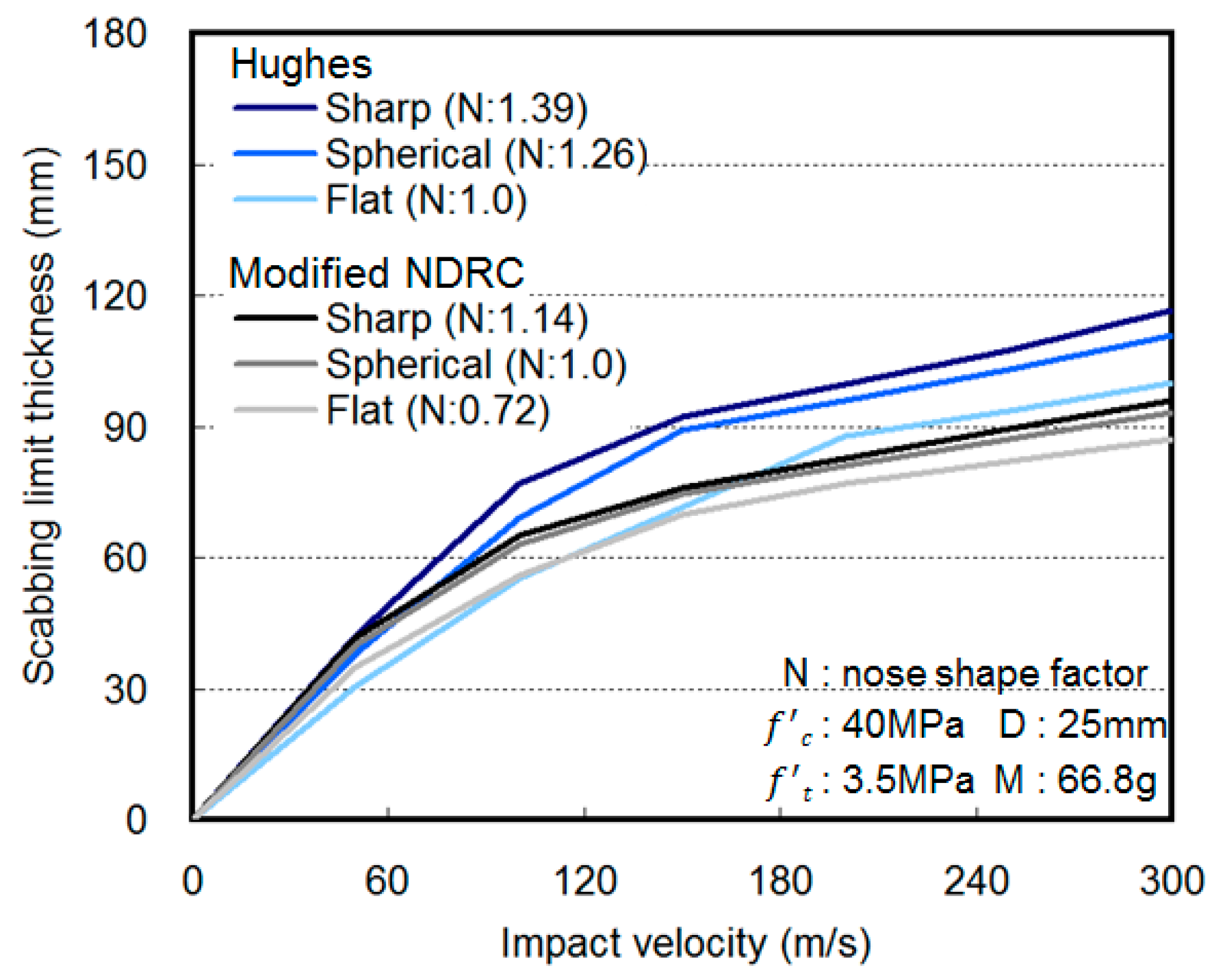
| Modified National Defense Research Committee NDRC [5] | |
| Penetration depth | Scabbing limit thickness |
| Hughes [6] | |
| Penetration depth | Scabbing limit thickness |
| Haldar and Hamieh [7] | |
| Penetration depth | Scabbing limit thickness |
| United Kingdom Atomic Energy Authority (UKAEA) [8] | |
| Penetration depth | Scabbing limit thickness |
| Impact Condition | Specimen Dimensions | ||||
|---|---|---|---|---|---|
| Projectile Nose Shape | Projectile Diameter (mm) | Projectile Weight (g) | Velocity (m/s) | Size (mm) | Thickness (mm) |
| Sharp | 25 | 66.8 (including carrier) | 170 | 700 × 600 (W × H) | 50, 60 |
| Hemispherical | |||||
| Flat | |||||
| ID | Fck (MPa) | W/B | S/a | Quantity of Materials (kg/m3) | Fiber | |||||
|---|---|---|---|---|---|---|---|---|---|---|
| W | C | FA | S | G | Vf (%) | (kg) | ||||
| NC | 50 | 0.4 | 0.55 | 220 | 440 | 110 | 774 | 655 | - | 0 |
| HSFRC | 1.0 | 78 | ||||||||
| Materials | Mechanical Properties |
|---|---|
| Cement | Ordinary Portland cement, Density: 3.15 g/cm3, Fineness: 3200 cm2/g |
| Fly ash | Density: 2.20 g/cm3, Fineness: 3000 cm2/g |
| River sand | Density: 2.61 g/cm3, Water absorption: 0.81% |
| Gravel | Crushed gravel, Maximum size: 20 mm, Density: 2.65 g/cm3, Water absorption: 0.76% |
| Superplasticizer | Polycarboxylic acid type |
| Hooked steel fiber | Length: 30 mm, Diameter: 0.5 mm, Aspect ratio: 60, Density: 7.80 g/cm3, Tensile strength: 1140 MPa |
| ID | Compressive Strength (MPa) | Flexural Strength (MPa) | Split Tensile Strength (MPa) |
|---|---|---|---|
| NC | 55.69 | 6.42 | 5.62 |
| HSFRC | 64.91 | 12.32 | 6.62 |
| Projectile Nose Shape | Thickness 50 mm | Thickness 60 mm | ||
|---|---|---|---|---|
| NC | HSFRC | NC | HSFRC | |
| Sharp |  |  |  |  |
| Hemi spherical |  |  |  |  |
| Flat |  |  |  |  |
© 2018 by the authors. Licensee MDPI, Basel, Switzerland. This article is an open access article distributed under the terms and conditions of the Creative Commons Attribution (CC BY) license (http://creativecommons.org/licenses/by/4.0/).
Share and Cite
Lee, S.; Kim, G.; Kim, H.; Son, M.; Choe, G.; Nam, J. Strain Behavior of Concrete Panels Subjected to Different Nose Shapes of Projectile Impact. Materials 2018, 11, 409. https://doi.org/10.3390/ma11030409
Lee S, Kim G, Kim H, Son M, Choe G, Nam J. Strain Behavior of Concrete Panels Subjected to Different Nose Shapes of Projectile Impact. Materials. 2018; 11(3):409. https://doi.org/10.3390/ma11030409
Chicago/Turabian StyleLee, Sangkyu, Gyuyong Kim, Hongseop Kim, Minjae Son, Gyeongcheol Choe, and Jeongsoo Nam. 2018. "Strain Behavior of Concrete Panels Subjected to Different Nose Shapes of Projectile Impact" Materials 11, no. 3: 409. https://doi.org/10.3390/ma11030409
APA StyleLee, S., Kim, G., Kim, H., Son, M., Choe, G., & Nam, J. (2018). Strain Behavior of Concrete Panels Subjected to Different Nose Shapes of Projectile Impact. Materials, 11(3), 409. https://doi.org/10.3390/ma11030409