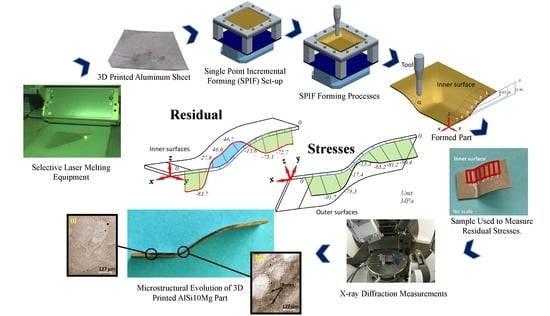
Experimental Determination of Residual Stresses Generated by Single Point Incremental Forming of AlSi10Mg Sheets Produced Using SLM Additive Manufacturing Process

 ,
,  ,
,  and
and
Abstract
1. Introduction
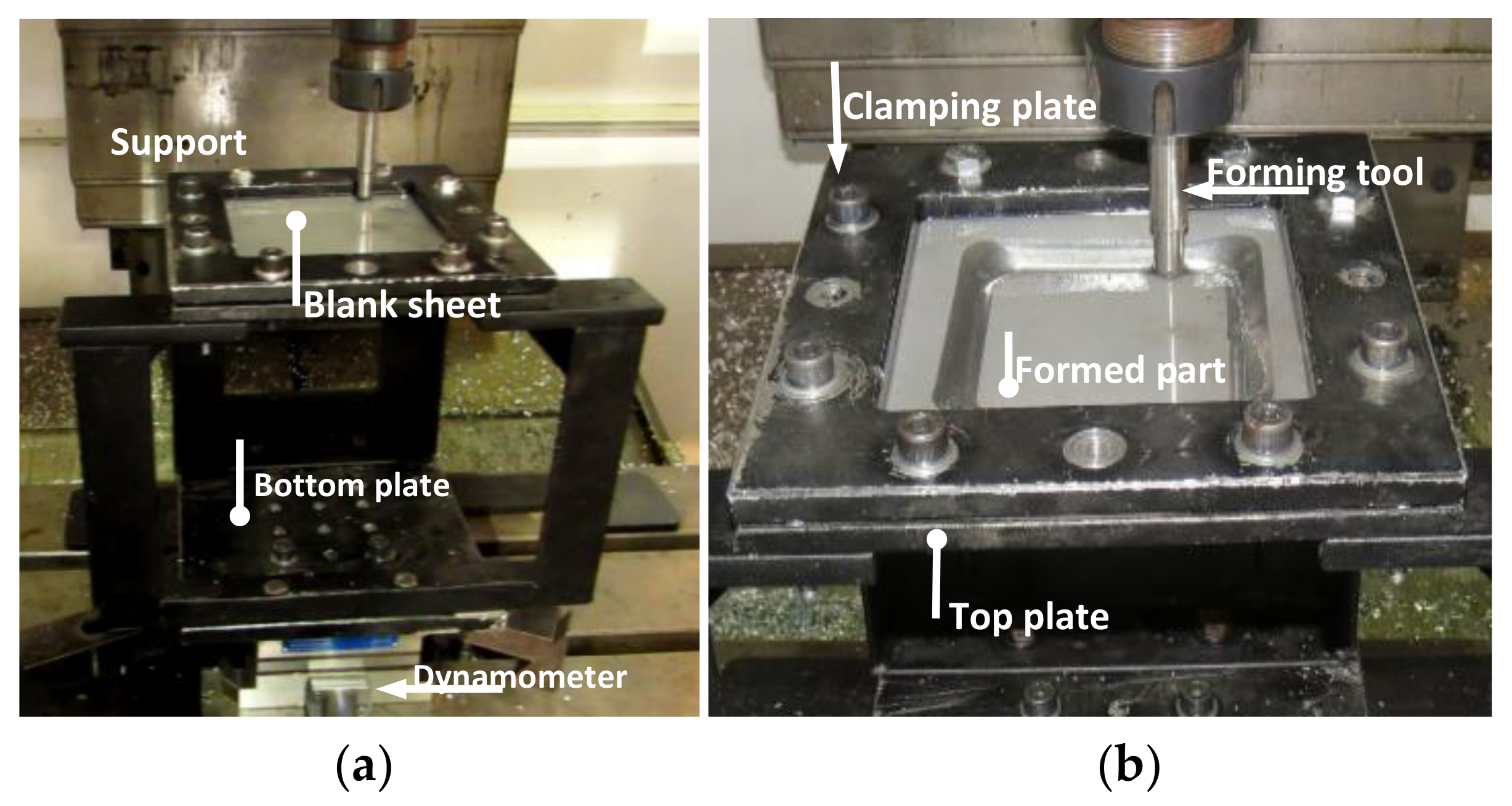
2. Materials and Methods
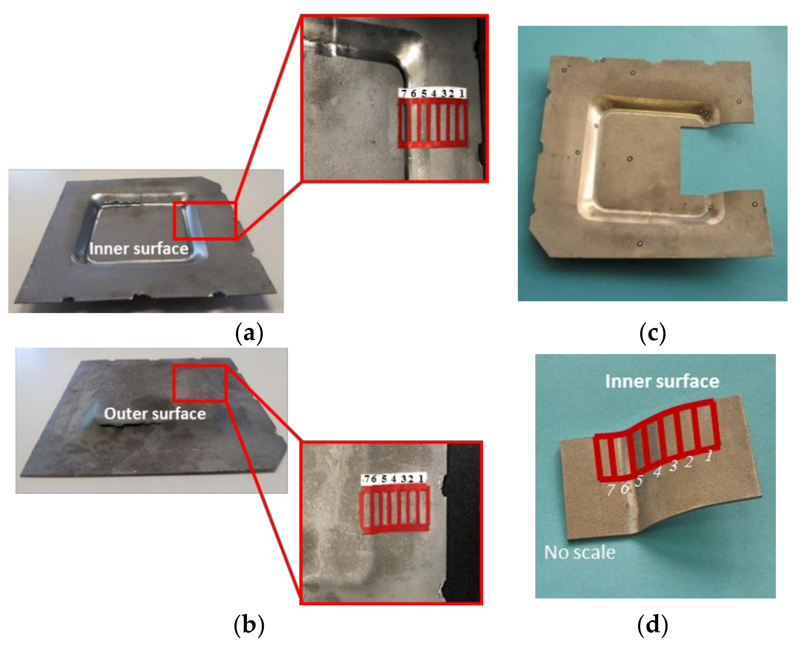
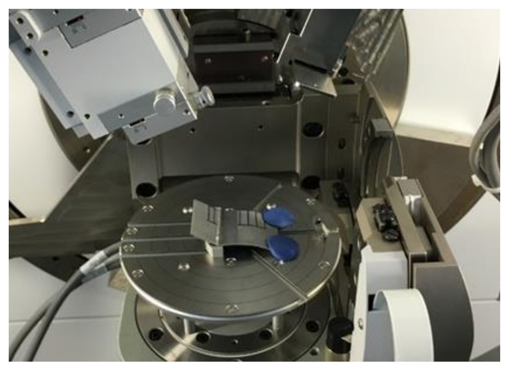
3. Experimental Measurements
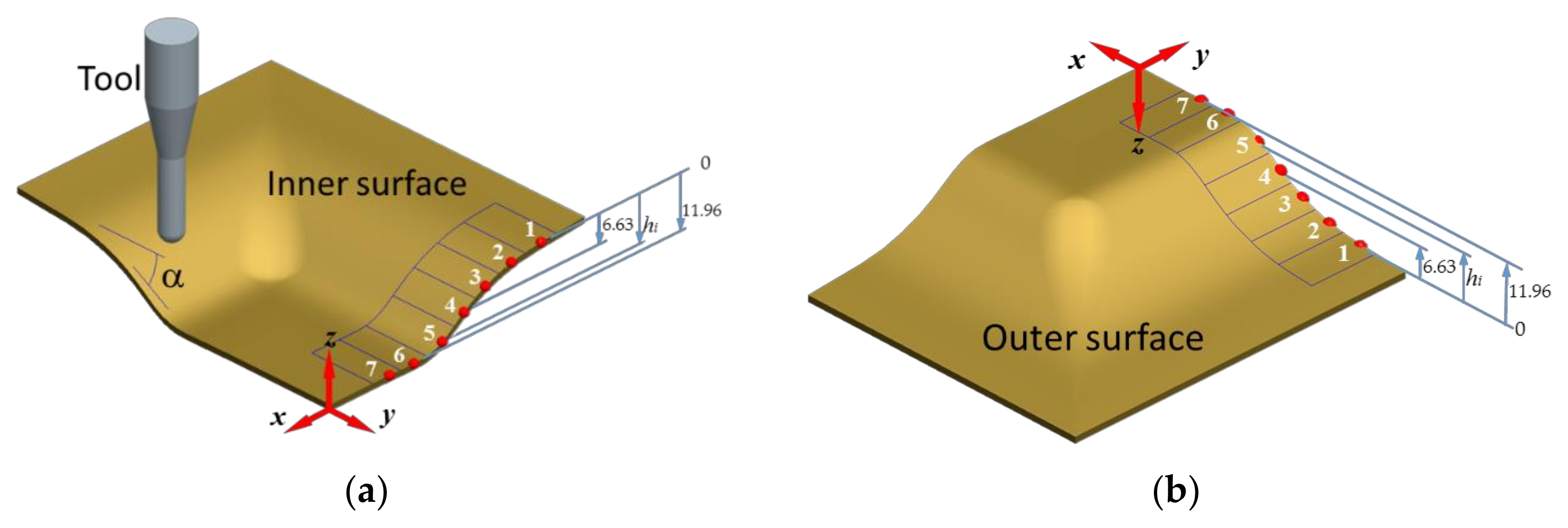
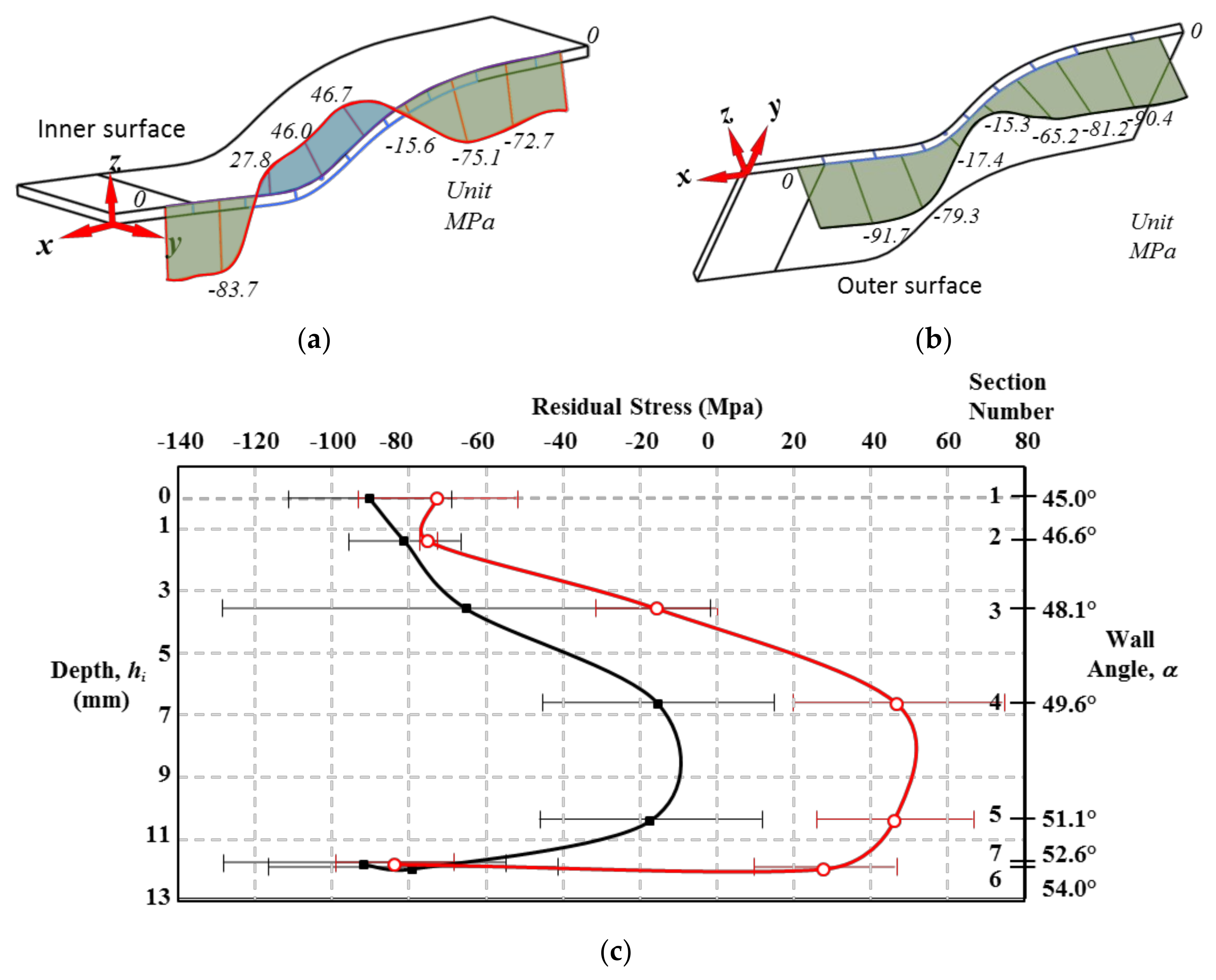
3.1. Determination of Residual Stresses
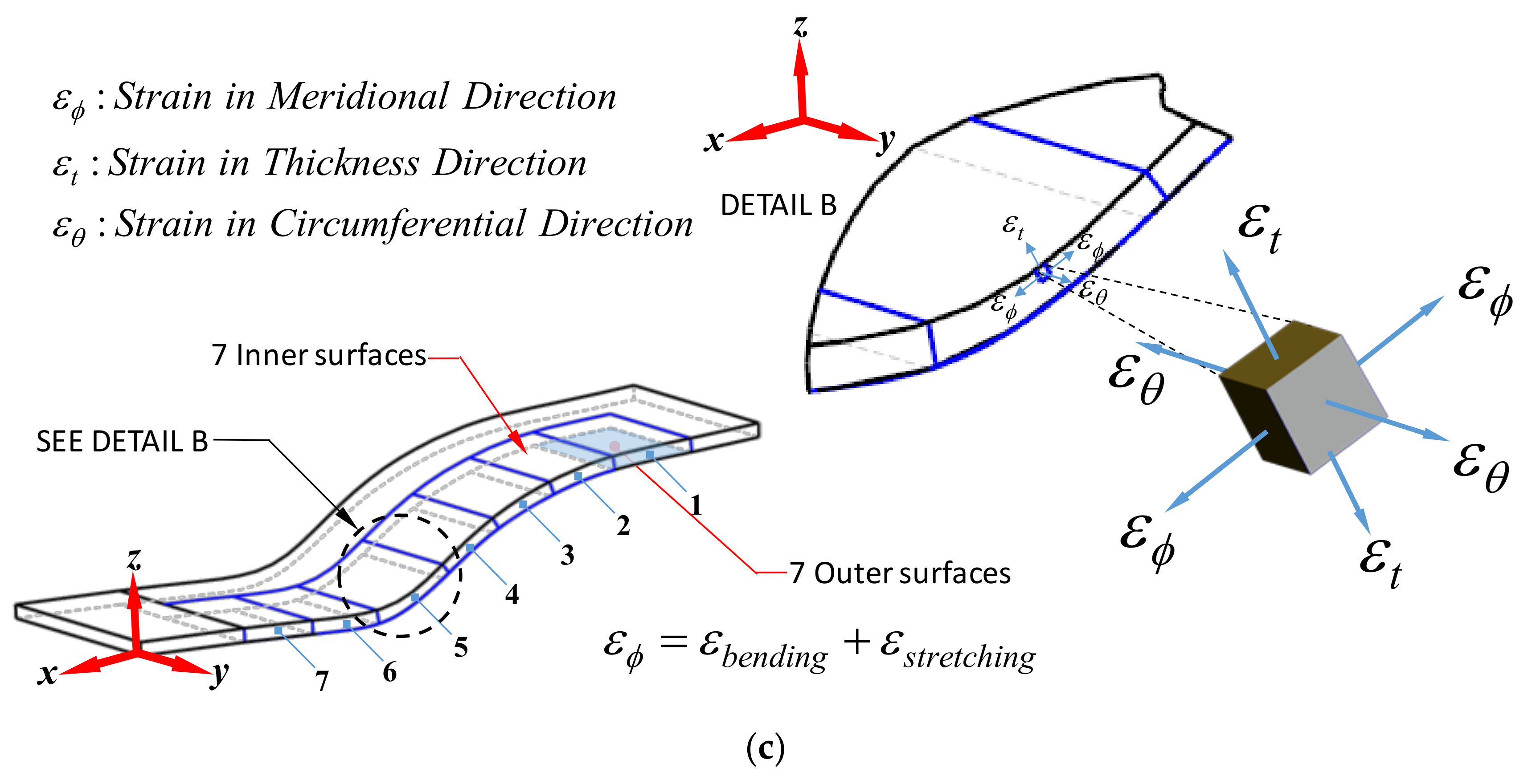
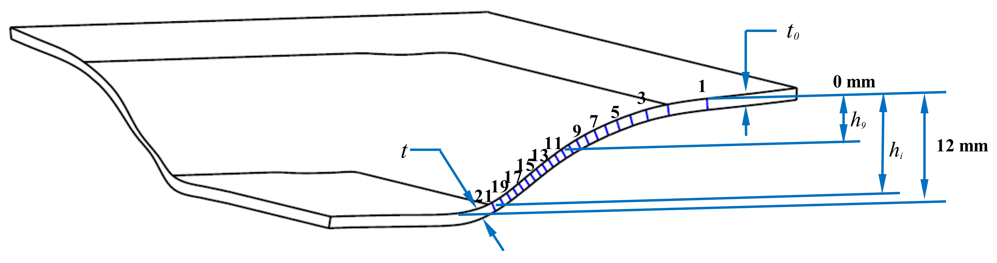
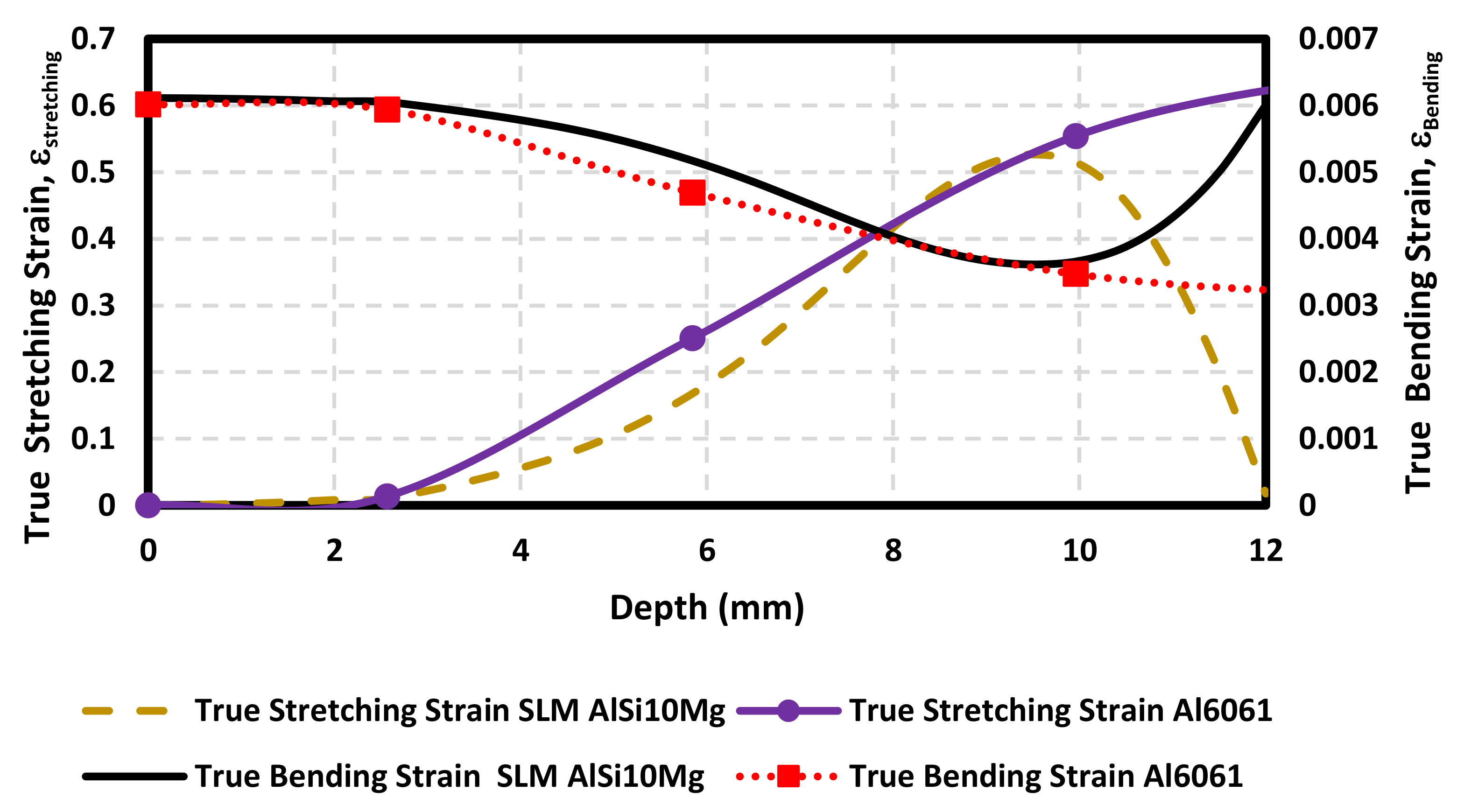
3.2. SPIFed Parts Mechanical Modelling
3.3. Mechanical Behavior of SLM AlSi10Mg SPIFed Samples
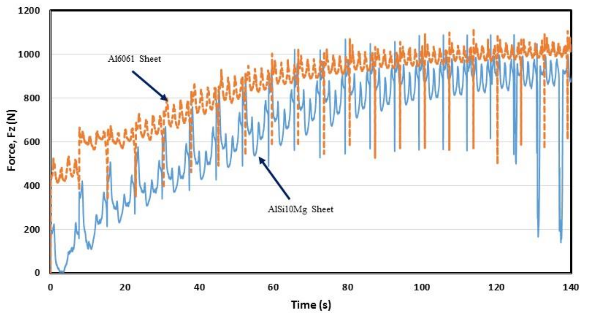
3.4. Comparison of the Mechanical Behavior of SLM AlSi10Mg and Al6061 SPIFed Samples
4. Microstructural Evolution During SPIF Process
5. Conclusions
Author Contributions
Funding
Acknowledgments
Conflicts of Interest
References
- Lee, J.Y.; An, J.; Chua, C.K. Fundamentals and applications of 3D printing for novel materials. Appl. Mater. Today 2017, 7, 120–133. [Google Scholar] [CrossRef]
- Brandt, M. (Ed.) Laser Additive Manufacturing, Materials, Design, Technologies and Applications; Woodhead Publishing: Cambridge, UK, 2017; pp. 55–77. ISBN 978-0-08-100433-3. [Google Scholar]
- Wohler Report 2017, 3D Printing and Additive Manufacturing State of the Industry Annual Worldwide Progress Report; Wohlers Associates, Inc.: Fort Collins, CO, USA, 2017; ISBN 978-0-9913332-3-3.
- 3D Printer and 3D Printing News. Available online: http://www.3ders.org (accessed on 9 December 2017).
- Attar, H.; Haghighi, S.E.; Kent, D.; Dargusch, M.S. Recent developments and opportunities in additive manufacturing of titanium-based matrix composites: A review. Int. J. Mach. Tools Manuf. 2018, 133, 85–102. [Google Scholar] [CrossRef]
- Attar, H.; Ehtemam-Haghighi, S.; Kent, D.; Wu, X.; Dargusch, M.S. Comparative study of commercially pure titanium produced by laser engineered net shaping, selective laser melting and casting processes. Mater. Sci. Eng. A 2017, 705, 385–393. [Google Scholar] [CrossRef]
- ASTM International, Technical Committees. 2016. Committee F42 on Additive Manufacturing Technologies. Available online: http://www.astm.org/COMMITTEE/F42.htm (accessed on 12 May 2017).
- Mercelis, P.; Kruth, J.P. Residual stresses in selective laser sintering and selective laser melting. Rapid Prototyp. J. 2006, 12, 254–265. [Google Scholar] [CrossRef]
- Kruth, J.; Froyen, L.; Van Vaerenbergh, J.; Mercelis, P.; Rombouts, M.; Lauwers, B. Selective laser melting of iron-based powder. J. Mater. Process. Technol. 2004, 149, 616–622. [Google Scholar] [CrossRef]
- Huang, X.; Liu, Z.; Xie, H. Recent progress in residual stress measurement techniques. Acta Mech. Solida Sin. 2013, 26, 570–583. [Google Scholar] [CrossRef]
- Vrancken, B.; Cain, V.; Knutsen, R.; Van Humbeeck, J. Residual stress via the contour method in compact tension specimens produced via selective laser melting. Scr. Mater. 2014, 87, 29–32. [Google Scholar] [CrossRef]
- King, W.; Anderson, A.T.; Ferencz, R.M.; Hodge, N.E.; Kamath, C.; Khairallah, S.A. Overview of modelling and simulation of metal powder bed fusion process at Lawrence Livermore National Laboratory. Mater. Sci. Technol. 2015, 31, 957–968. [Google Scholar] [CrossRef]
- Jabbari, M.; Baran, I.; Mohanty, S.; Comminal, R.; Sonne, M.R.; Nielsen, M.W.; Spangenberg, J.; Hattel, J.H. Multiphysics modelling of manufacturing processes: A review. Adv. Mech. Eng. 2018, 10, 1–31. [Google Scholar] [CrossRef]
- DebRoy, T.; Wei, H.L.; Zuback, J.S.; Mukherjee, T.; Elmer, J.W.; Milewski, J.O.; Beese, A.M.; Wilson-Heid, A.; Ded, A.; Zhang, W. Additive manufacturing of metallic components—Process, structure and properties. Prog. Mater. Sci. 2018, 92, 112–224. [Google Scholar] [CrossRef]
- Yap, C.Y.; Chua, C.K.; Dong, Z.L.; Liu, Z.H.; Zhang, D.Q.; Loh, L.E.; Sing, S.L. Review of selective laser melting: Materials and applications. Appl. Phys. Rev. 2015, 2, 041101. [Google Scholar] [CrossRef]
- Greitemeier, D.; Dalle Donne, C.; Syassen, F.; Eufinger, J.; Melz, T. Effect of surface roughness on fatigue performance of additive manufactured Ti–6Al–4V. Mater. Sci. Technol. 2016, 32, 629–634. [Google Scholar] [CrossRef]
- Jiménez, I.; López, C.; Martínez-Romero, O.; Siller, H.R.; Diabb, J.; Elías-Zúñiga, A. Investigation of residual stress distribution in single point incremental forming of aluminum parts by X-ray diffraction technique. Int. J. Adv. Manuf. Technol. 2017, 91, 2571–2580. [Google Scholar] [CrossRef]
- Wu, J.; Wang, L.; An, X. Numerical analysis of residual stress evolution of AlSi10Mg manufactured by selective laser melting. Optik 2017, 137, 65–78. [Google Scholar] [CrossRef]
- Kempen, K.; Thijs, L.; Van Humbeeck, J.; Kruth, J.P. Mechanical properties of AlSi10Mg produced by selective laser melting. Phys. Procedia 2012, 39, 439–446. [Google Scholar] [CrossRef]
- Malhotra, R.; Xue, L.; Belytschko, T.; Cao, J. Mechanics of fracture in single point incremental forming. J. Mater. Process. Technol. 2012, 212, 1573–1590. [Google Scholar] [CrossRef]
- Kalpakjian, S.; Schmid, S. Manufacturing Processes for Engineering Materials, 5th ed.; Pearson: London, UK, 2008; ISBN 978-0132272711. [Google Scholar]
- Young, D.; Jeswiet, J. Wall thickness variations in single-point incremental forming. J. Eng. Manuf. Part B 2004, 218, 1453–1459. [Google Scholar] [CrossRef]
- Isik, K.; Silva, M.B.; Tekkaya, A.E.; Martins, P.A.F. Formability limits by fracture in sheet metal forming. J. Mater. Process. Technol. 2014, 214, 1557–1565. [Google Scholar] [CrossRef]
- Wu, J.; Wang, X.Q.; Wang, W.; Attallah, M.M.; Loretto, M.H. Microstructure and strength of selectively laser melted AlSi10Mg. Acta. Mater. 2016, 117, 311–320. [Google Scholar] [CrossRef]
- Li, X.P.; Ji, G.; Chen, Z.; Addad, A.; Wu, Y.; Wang, H.W.; Vleugels, J.; Van Humbeeck, J.; Kruth, J.P. Selective laser melting of nano-TiB2 decorated AlSi10Mg alloy with high fracture strength and ductility. Acta Mater. 2017, 129, 183–193. [Google Scholar] [CrossRef]
- Chen, B.; Moon, S.K.; Yao, X.; Bi, G.; Shen, J.; Umeda, J.; Kondoh, K. Strength and strain hardening of a selective laser melted AlSi10Mg alloy. Scr. Mater. 2017, 141, 45–49. [Google Scholar] [CrossRef]
- Aboulkhair, N.T.; Everitt, N.M.; Ashcroft, I.; Tuck, C. Reducing porosity in AlSi10Mg parts processed by selective laser melting. Addit. Manuf. 2014, 1, 77–86. [Google Scholar] [CrossRef]
- Olakanmi, E.O.; Cochrane, R.F.; Dalgarno, K.W. A review on selective laser sintering/melting (SLS/SLM) of aluminium alloy powders: Processing, microstructure, and properties. Prog. Mater. Sci. 2015, 74, 401–477. [Google Scholar] [CrossRef]
- Ming, T. Inclusions, Porosity, and Fatigue of AlSi10Mg Parts Produced by Selective Laser Melting. Ph.D Thesis, Carnegie Mellon University, Pittsburgh, PA, USA, 18 April 2017. Available online: http://repository.cmu.edu/dissertations/903 (accessed on 20 March 2018).
- Silva, M.B.; Isik, K.; Tekkaya, A.E.; Martins, P.A.F. Fracture Loci in Sheet Metal Forming: A Review. Acta Metall. Sin. (Engl. Lett.) 2015, 28, 1415–1425. [Google Scholar] [CrossRef]
- Wang, Q.G. Microstructural effects on the tensile and fracture behavior of Aluminum casting alloys A356/357. Metall. Mater. Trans. A 2003, 34, 2887–2899. [Google Scholar] [CrossRef]
- Yadroitsev, I.; Thivillon, L.; Bertrand, P.; Smurov, I. Strategy of manufacturing components with designed internal structure by selective laser melting of metallic powder. Appl. Surf. Sci. 2007, 254, 980–983. [Google Scholar] [CrossRef]
- Franco, B.E.; Ma, J.; Loveall, B.; Tapia, G.A.; Karayagiz, K.; Liu, J.; Elwany, A.; Arroyave, R.; Karaman, I. A sensory material approach for reducing variability in additively manufactured metal parts. Sci. Rep. 2017, 7, 3604. [Google Scholar] [CrossRef]
- Tang, M.; Pistorius, P.C. Oxides, porosity and fatigue performance of AlSi10Mg parts produced by selective laser melting. Int. J. Fatigue 2017, 94, 192–201. [Google Scholar] [CrossRef]


| Section Number | Depth hi (mm) | Wall Thickness t (mm) | Outer Surface | Inner Surface | ||
|---|---|---|---|---|---|---|
| Residual Stress (MPa) | Standard Deviation (MPa) (+/−) | Residual Stress (MPa) | Standard Deviation (MPa) (+/−) | |||
| 1 | 0 | 1.226 | −90.4 | 21.1 | −72.7 | 40.7 |
| 2 | 1.39 | 1.220 | −81.2 | 14.4 | −75.1 | 4.7 |
| 3 | 3.57 | 1.060 | −65.2 | 63.6 | −15.6 | 31.5 |
| 4 | 6.63 | 1.017 | −15.3 | 30.0 | 46.7 | 54.4 |
| 5 | 10.41 | 0.730 | −17.4 | 28.8 | 46.0 | 40.5 |
| 6 | 11.96 | 1.012 | −79.3 | 37.3 | 27.8 | 36.4 |
| 7 | 11.81 | 1.225 | −91.7 | 36.6 | −83.7 | 30.8 |
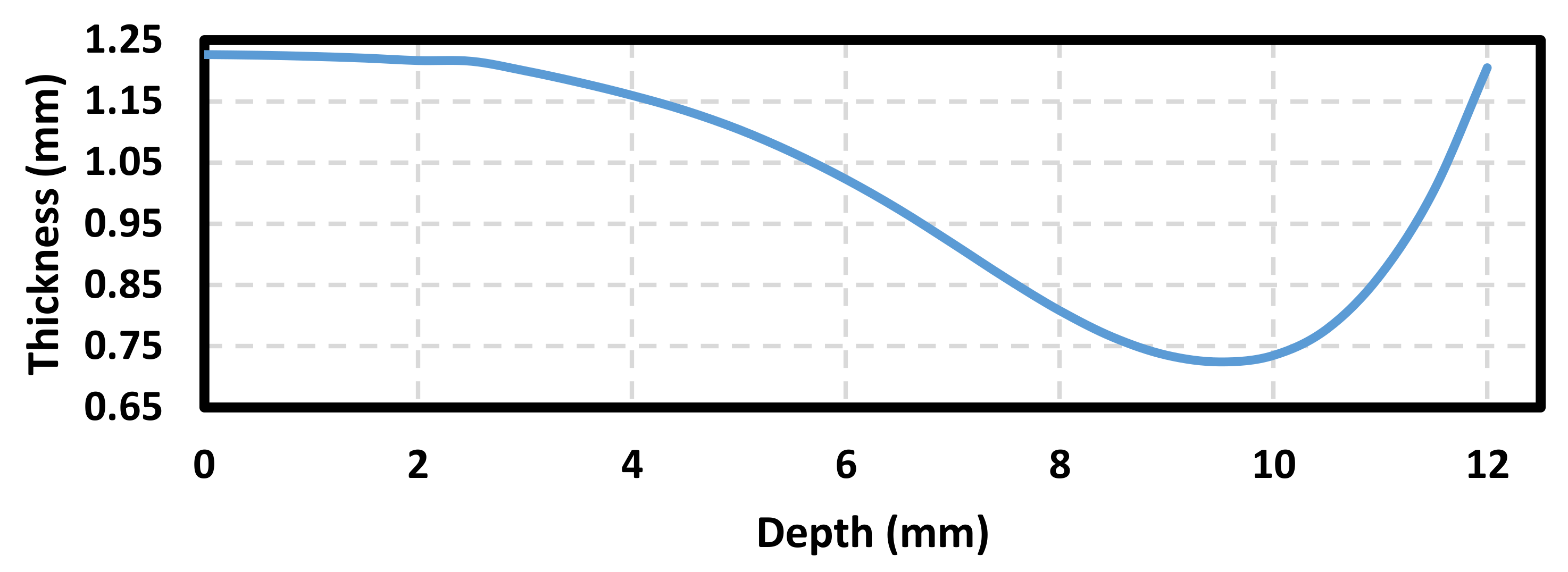
| Point | Depth hi (mm) | Thickness t (mm) | Point | Depth hi (mm) | Thickness t (mm) | Point | Depth hi (mm) | Thickness t (mm) |
|---|---|---|---|---|---|---|---|---|
| 1 | 0 | 1.226 | 8 | 3.5 | 1.181 | 15 | 7.0 | 0.917 |
| 2 | 0.5 | 1.225 | 9 | 4.0 | 1.159 | 16 | 7.5 | 0.860 |
| 3 | 1.0 | 1.223 | 10 | 4.5 | 1.134 | 17 | 8.0 | 0.808 |
| 4 | 1.5 | 1.220 | 11 | 5..0 | 1.104 | 18 | 8.5 | 0.764 |
| 5 | 2.0 | 1.216 | 12 | 5.5 | 1.064 | 19 | 9.0 | 0.735 |
| 6 | 2.5 | 1.215 | 13 | 6.0 | 1.022 | 20 | 9.5 | 0.724 |
| 7 | 3.0 | 1.198 | 14 | 6.5 | 0.973 | 21 | 10.0 | 0.735 |
| Point | Depth hi (mm) | Thickness t (mm) | Point | Depth hi (mm) | Thickness t (mm) |
|---|---|---|---|---|---|
| 1 | 2.565 | 1.1981 | 10 | 38.213 | 0.3817 |
| 2 | 5.842 | 0.9454 | 11 | 41.212 | 0.3594 |
| 3 | 9.957 | 0.6978 | 12 | 45.024 | 0.3189 |
| 4 | 14.258 | 0.6204 | 13 | 48.553 | 0.2755 |
| 5 | 18.833 | 0.5747 | 14 | 51.954 | 0.3303 |
| 6 | 23.714 | 0.5329 | 15 | 54.682 | 0.6798 |
| 7 | 27.577 | 0.4918 | 16 | 54.818 | 1.1588 |
| 8 | 31.253 | 0.4526 | 17 | 54.756 | 1.2102 |
| 9 | 34.562 | 0.4281 | 18 | 54.874 | 1.2144 |
© 2018 by the authors. Licensee MDPI, Basel, Switzerland. This article is an open access article distributed under the terms and conditions of the Creative Commons Attribution (CC BY) license (http://creativecommons.org/licenses/by/4.0/).
Share and Cite
López, C.; Elías-Zúñiga, A.; Jiménez, I.; Martínez-Romero, O.; R. Siller, H.; Diabb, J.M. Experimental Determination of Residual Stresses Generated by Single Point Incremental Forming of AlSi10Mg Sheets Produced Using SLM Additive Manufacturing Process. Materials 2018, 11, 2542. https://doi.org/10.3390/ma11122542
López C, Elías-Zúñiga A, Jiménez I, Martínez-Romero O, R. Siller H, Diabb JM. Experimental Determination of Residual Stresses Generated by Single Point Incremental Forming of AlSi10Mg Sheets Produced Using SLM Additive Manufacturing Process. Materials. 2018; 11(12):2542. https://doi.org/10.3390/ma11122542
Chicago/Turabian StyleLópez, Cecilio, Alex Elías-Zúñiga, Isaac Jiménez, Oscar Martínez-Romero, Héctor R. Siller, and José M. Diabb. 2018. "Experimental Determination of Residual Stresses Generated by Single Point Incremental Forming of AlSi10Mg Sheets Produced Using SLM Additive Manufacturing Process" Materials 11, no. 12: 2542. https://doi.org/10.3390/ma11122542
APA StyleLópez, C., Elías-Zúñiga, A., Jiménez, I., Martínez-Romero, O., R. Siller, H., & Diabb, J. M. (2018). Experimental Determination of Residual Stresses Generated by Single Point Incremental Forming of AlSi10Mg Sheets Produced Using SLM Additive Manufacturing Process. Materials, 11(12), 2542. https://doi.org/10.3390/ma11122542