Drilling Process in γ-TiAl Intermetallic Alloys


Abstract
:1. Introduction
2. Experimental Procedure
2.1. Material
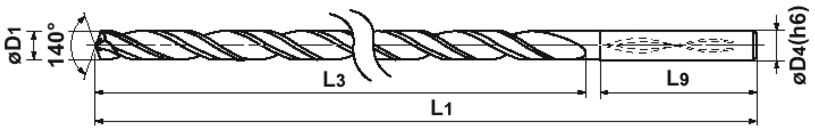
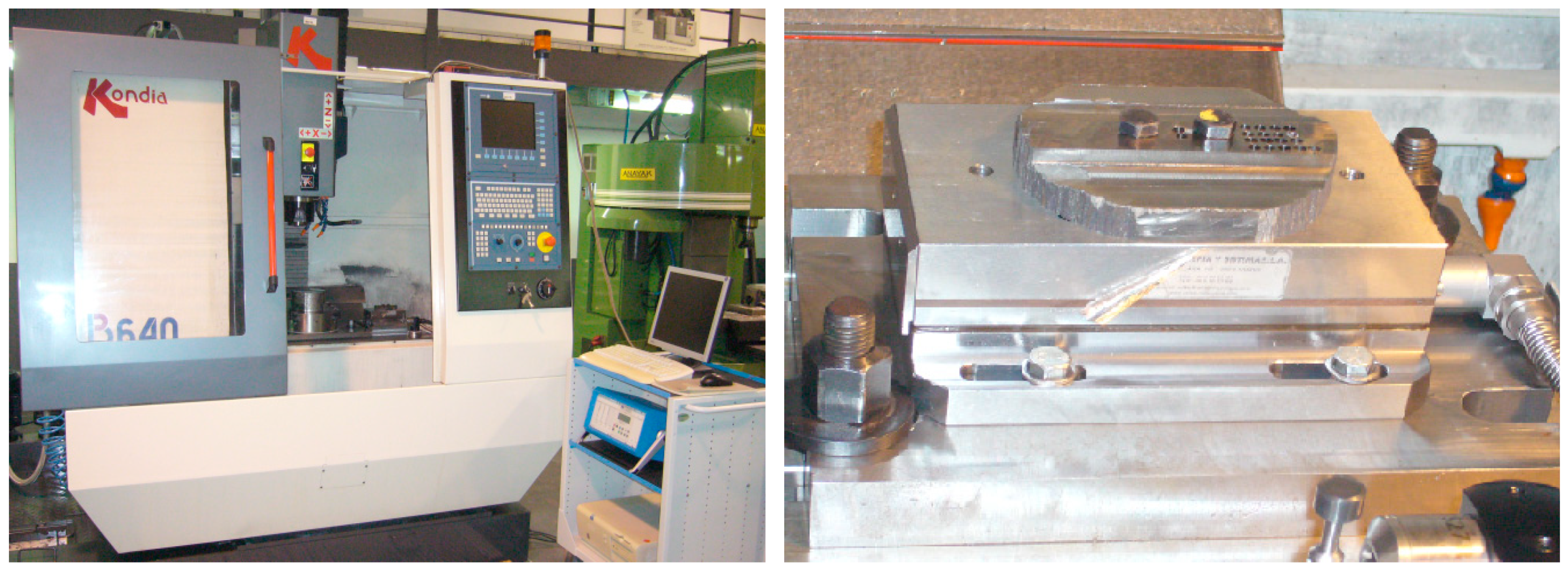
2.2. Equipment
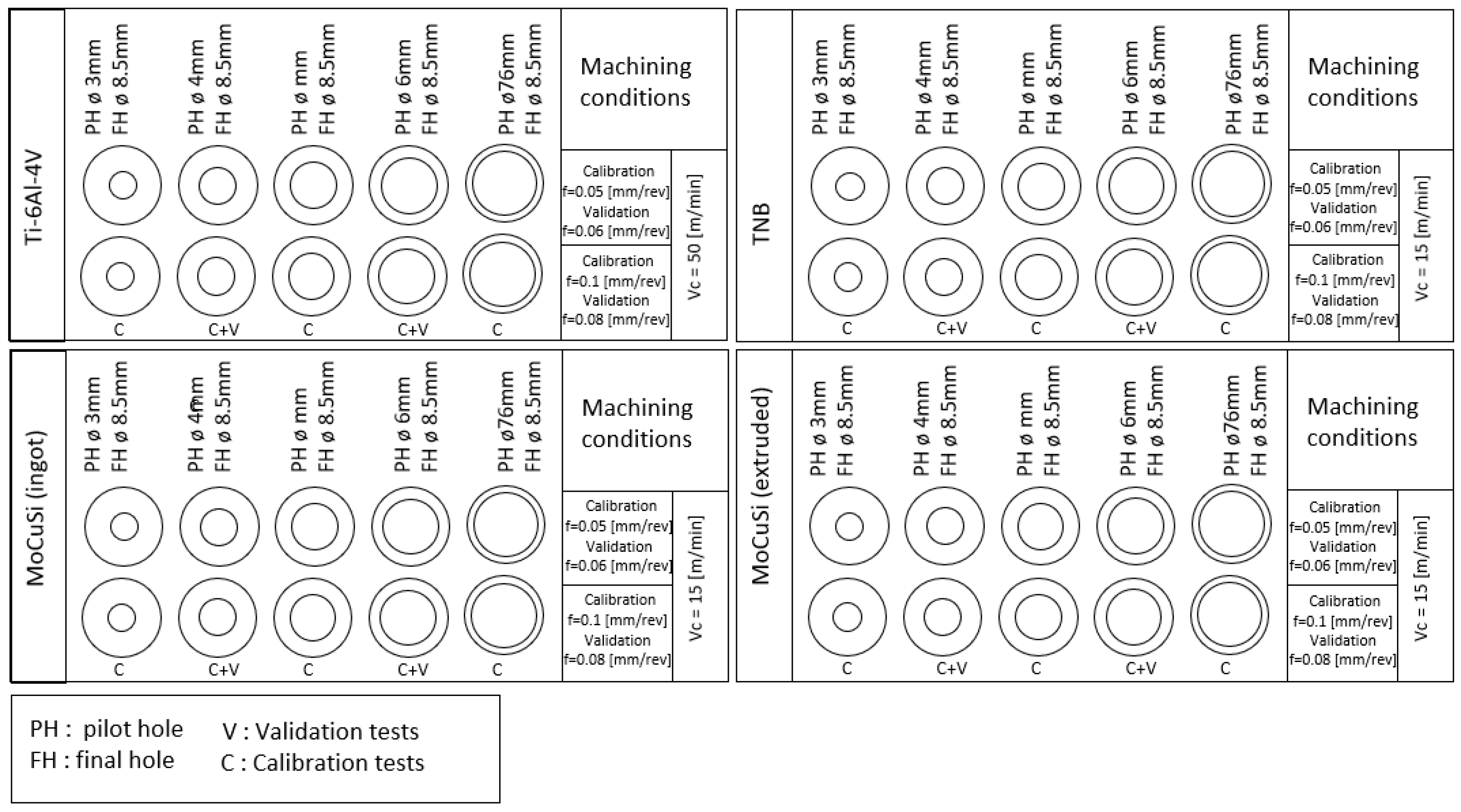
2.3. Machining Conditions
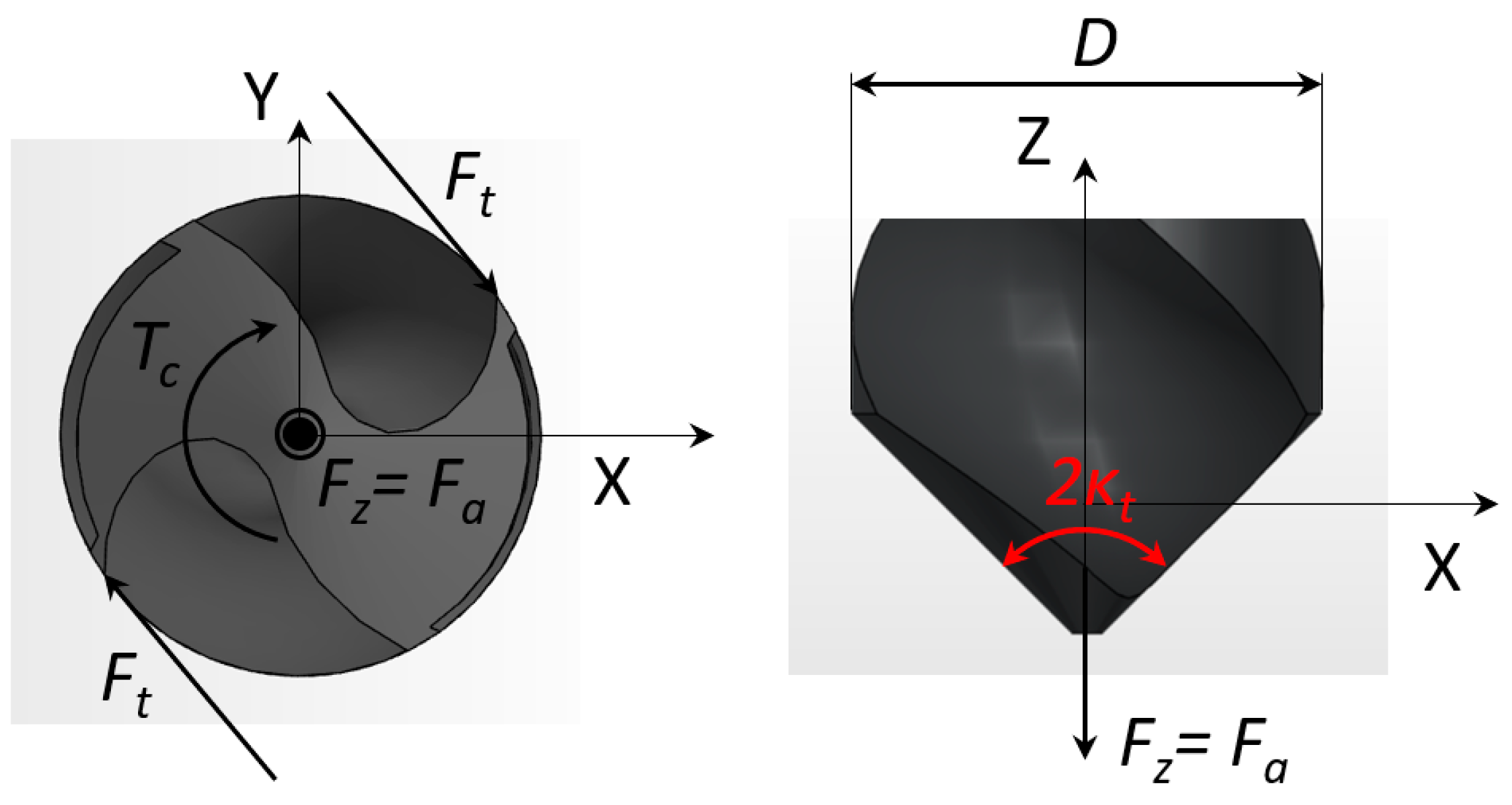
3. Cutting Forces Prediction Mechanistic Model
4. Results
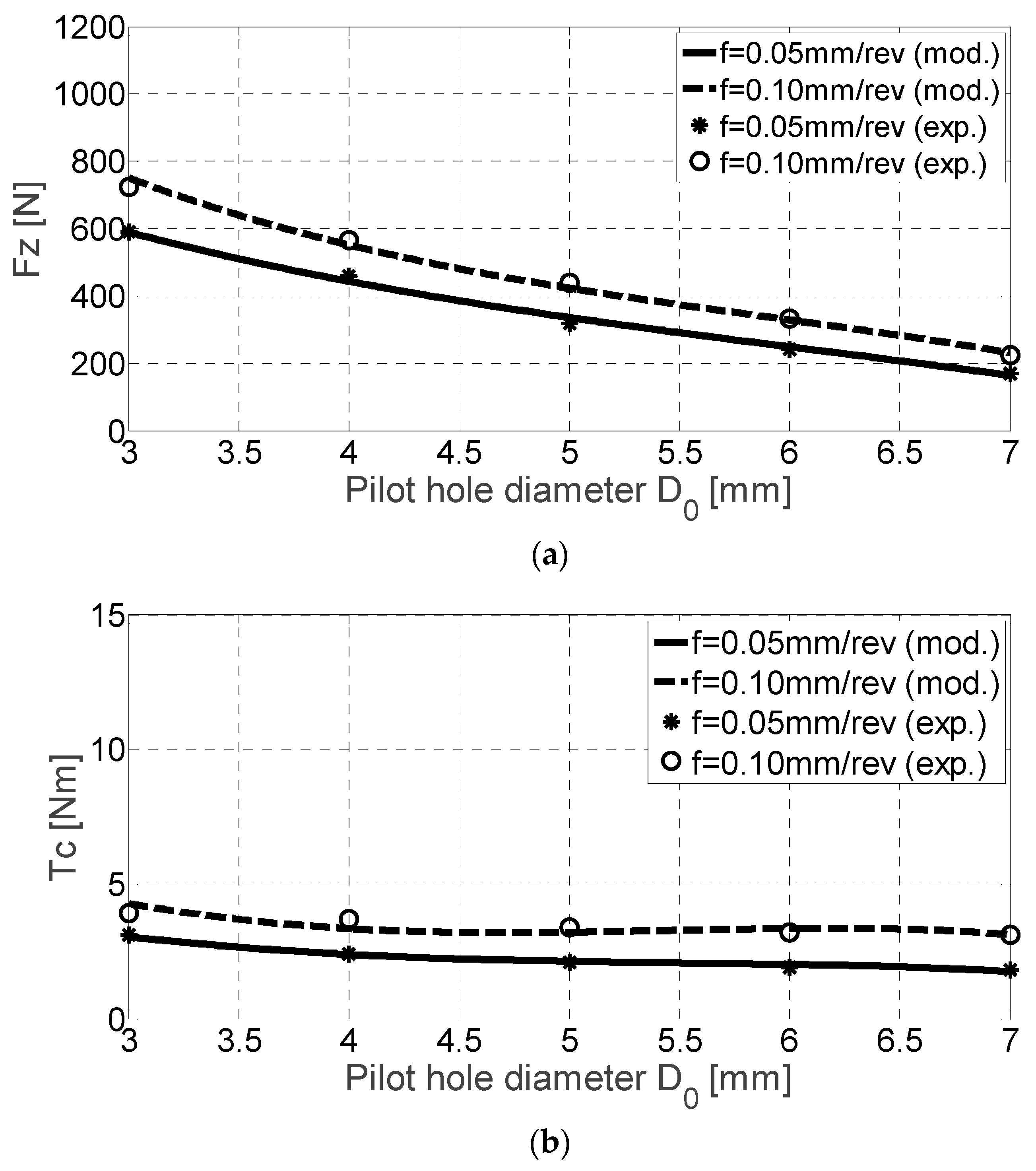
4.1. Results for Ti-6Al-4V Alloy
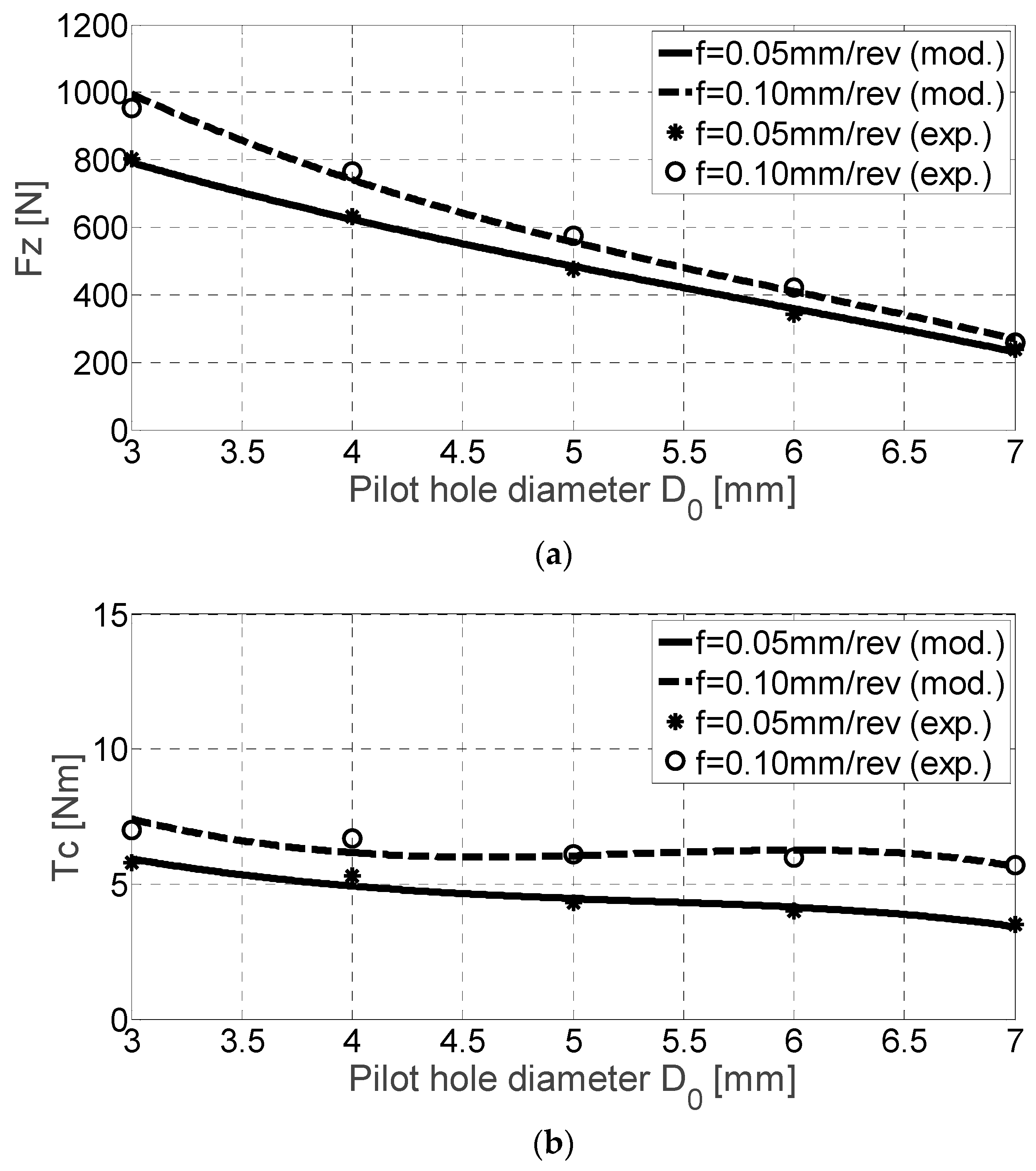
4.2. Results for TNB Alloy
4.3. Results for Ingot MoCuSi Alloy
4.4. Results for Extruded MoCuSi Alloy
5. Conclusions
- These alloys present a much smaller machinability than conventional titanium alloys.
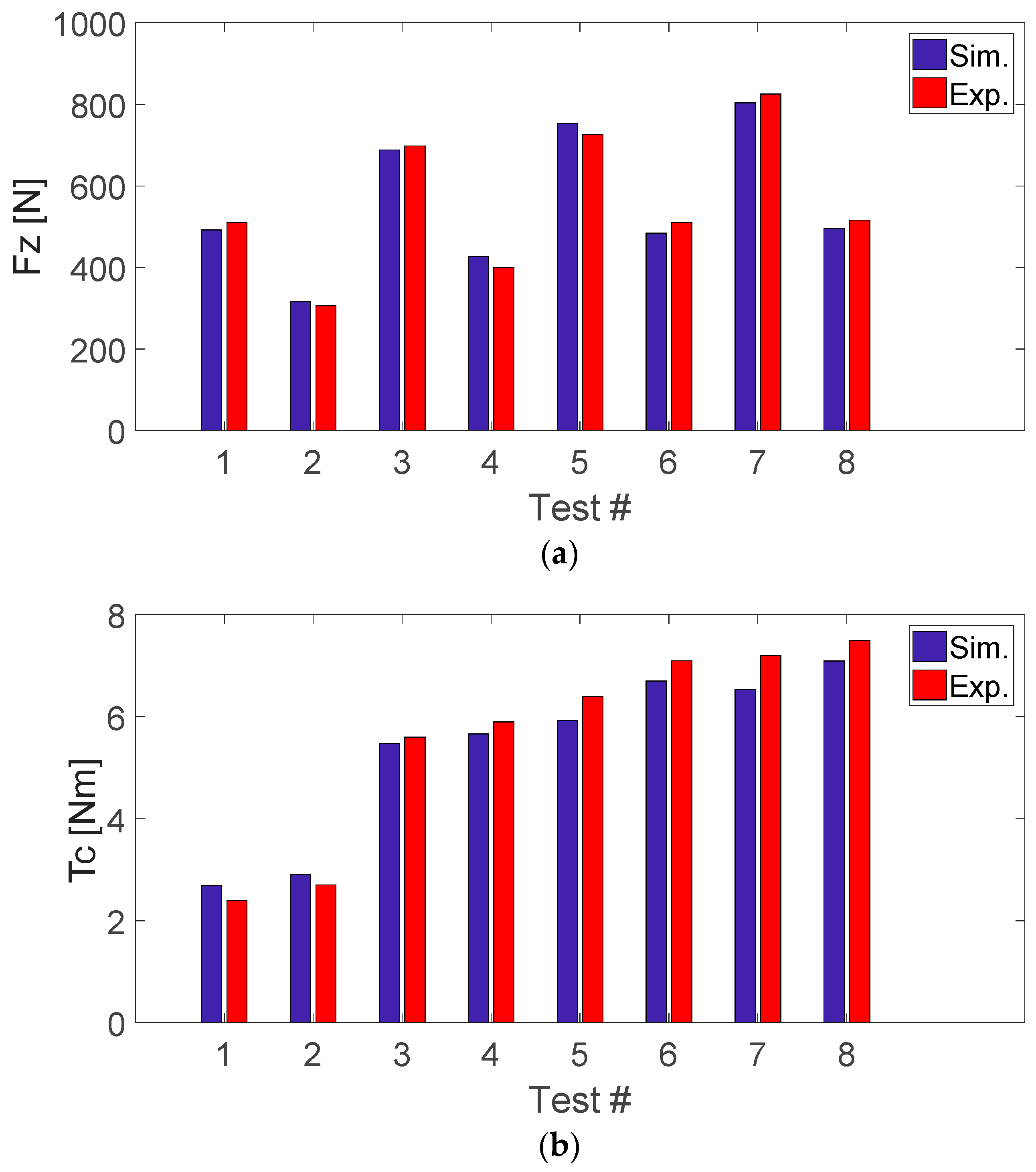
- The presented mechanistic stationary model is capable of simulating the thrust force and cutting torque in the drilling process. The influence of vibratory effects, lateral vibrations or runout was not considered. After model calibration, validation tests were done, showing a good agreement.
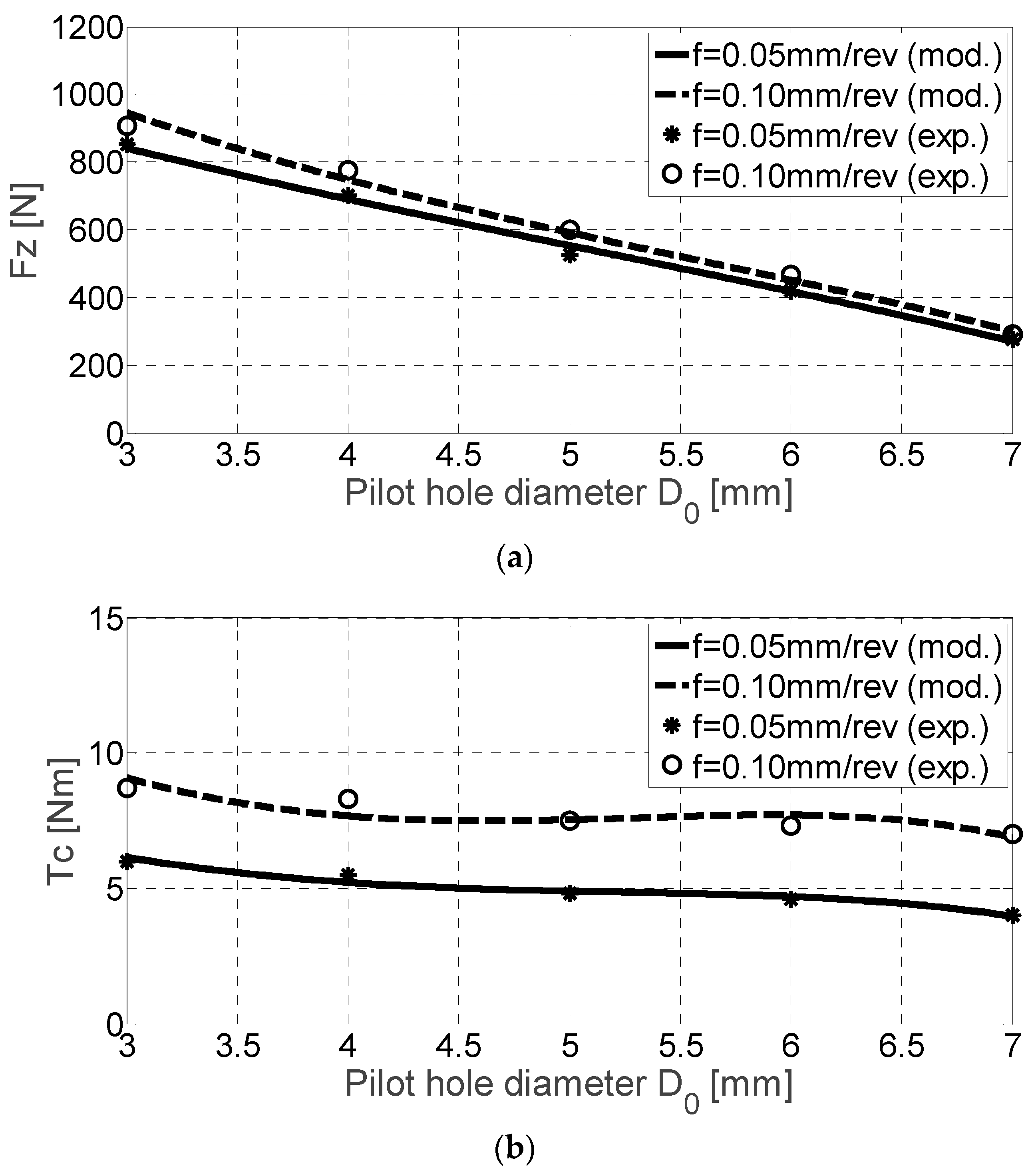
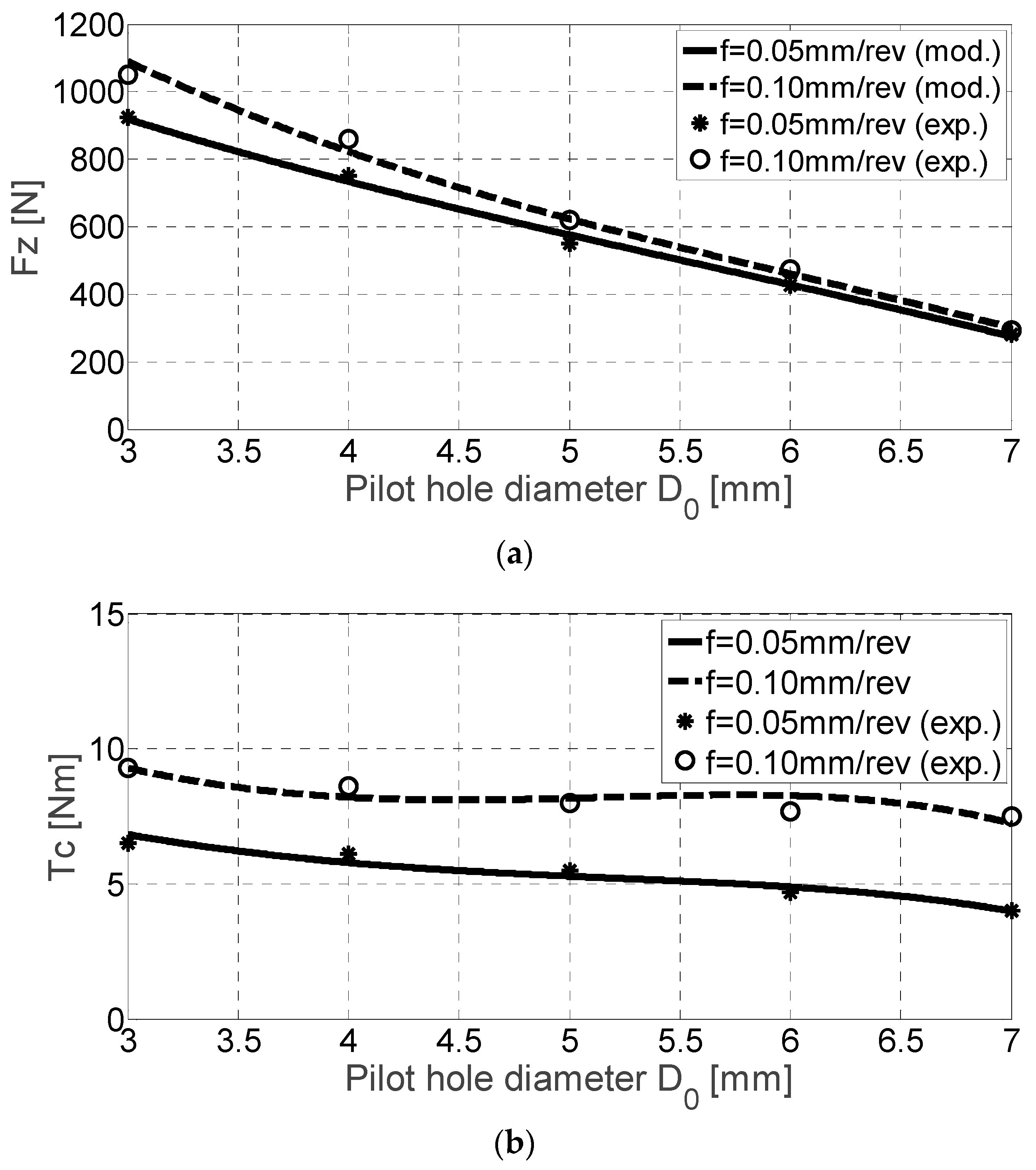
- Experimental drilling tests done to evaluate the machinability of these difficult-to-cut materials (the high cost of the tested materials (approx. 400 €/kg) limited the number of tests and a stronger experimental design) show that the obtained cutting coefficients present a quasi-linear dependence on the pilot hole D0 for the axial force Fz, while a cubic is more suitable in the case of Tc.
- Experiments demonstrated large differences between the more conventional Ti6Al4V alloy and the three γ-TiAl intermetallic alloys. As the mechanical properties of extruded/ingot alloys are higher than those of the TNB alloy, this trend is inversely true for the machinability grade. Tests proved that MoCuSi alloys are the toughest materials.
- Despite the good results during the validation, a statistical approach would be desirable to test any differences in material series, machine tools, as well as to build more complete models. Wear studies including process damping effects can be subjects for future research works.
Author Contributions
Funding
Acknowledgments
Conflicts of Interest
References
- Homepage of Boeing. Available online: http://www.boeing.com (accessed on 20 October 2018).
- Martin, R.; Evans, D. Reducing Costs in Aircraft: The Metals Affordability Initiative Consortium. JOM 2000, 52, 24–28. [Google Scholar] [CrossRef]
- Voice, W.E.; Henderson, M.; Shelton, E.F.J.; Wu, X. Gamma titanium aluminide-TNB. Intermetallics 2005, 13, 959–964. [Google Scholar] [CrossRef]
- Boyer, R.R. An overview on the use of titanium in the aerospace industry. Mater. Sci. Eng. A 1996, 213, 103–114. [Google Scholar] [CrossRef]
- Jha, A.K.; Singh, S.K.; Kiranmayee, M.S.; Sreekumar, K.; Sinha, P.P. Failure analysis of titanium alloy (Ti6Al4V) fastener used in aerospace application. Eng. Fail. Anal. 2010, 17, 1457–1465. [Google Scholar] [CrossRef]
- Murr, L.E.; Quinones, S.A.; Gaytan, S.M.; López, M.I.; Rodela, A.; Martinez, E.Y.; Hernandez, D.H.; Martinez, E.; Medina, F.; Wicker, R.B. Microstructure and mechanical behavior of Ti-6Al-4 V produced by rapid-layer manufacturing for biomedical applications. J. Mech. Behav. Biomed. Mater. 2009, 2, 20–32. [Google Scholar] [CrossRef] [PubMed]
- Yamaguchi, M.; Inui, H.; Ito, K. High temperature structural intermetallics. Acta Mater. 2000, 48, 307–322. [Google Scholar] [CrossRef]
- Jozwik, J. Evaluation of Tribological Properties and Condition of Ti6Al4V Titanium Alloy Surface. Tehnički vjesn. 2018, 25, 170–175. [Google Scholar] [CrossRef] [Green Version]
- Kim, Y.W.; Dimiduk, D.M. Gamma TiAl alloys: Emerging new structural metallic materials. In Proceedings of the ICETS 2000-ISAM, Beijing, China, 1 October 2000. [Google Scholar]
- Semiatin, S.L.; Seetharaman, V.; Weiss, I. Hot workability of titanium and titanium aluminide alloys. Mater. Sci. Eng. 1998, 243, 1–24. [Google Scholar] [CrossRef]
- López de Lacalle, L.N.; Perez, J.; Llorente, J.I.; Sanchez, J.A. Advanced cutting conditions for the milling of aeronautical alloys. J. Mater. Process. Technol. 2000, 100, 1–11. [Google Scholar] [CrossRef]
- Kuczmaszewski, J.; Kazimierz, Z.; Matuszak, J.; Pałka, T.; Mądry, J. Studies on the effect of mill microstructure upon tool life during slot milling of Ti6Al4V alloy parts. Eksploat. I Niezawodn. Maint. Reliab. 2017, 19, 590–596. [Google Scholar] [CrossRef]
- Józwik, J.; Ostrowski, D.; Milczarczyk, R.; Krolczyk, G.M. Analysis of relation between the 3D printer laser beam power and the surface morphology properties in Ti-6Al-4V titanium alloy parts. J. Braz. Soc. Mech. Sci. Eng. 2018, 40, 1678–5878. [Google Scholar] [CrossRef]
- Aspinwall, D.K.; Dewes, R.C.; Mantle, A.L. The Machining of γ-TiAl Intermetallic Alloys. CIRP Ann. 2005, 54, 99–104. [Google Scholar] [CrossRef]
- Arrazola, P.J.; Garay, A.; Iriarte, L.M.; Armendia, M.; Marya, S.; Maitre, F.L. Machinability of titanium alloys (Ti6Al4V and Ti555.3). J. Mater. Process. Technol. 2009, 209, 2223–2230. [Google Scholar] [CrossRef]
- Beranoagirre, A.; López de Lacalle, L.N. Grinding of Gamma TiAl Intermetallic Alloys. Proc. Eng. 2013, 63, 489–498. [Google Scholar] [CrossRef]
- Lindemann, J.; Glavatskikh, M.; Leyens, C. Surface effects on the mechanical properties of gamma titanium aluminides. In Proceedings of the International Conference on Processing & Manufacturing of Advanced Materials, Quebec City, QC, Canada, 1–5 August 2011; pp. 1071–1076. [Google Scholar]
- Hood, T.; Aspinwall, D.K.; Sage, C.; Voice, W. High speed ball nose and milling of γ-TiAl alloys. Intermetallics 2013, 32, 284–291. [Google Scholar] [CrossRef]
- Thepsonthi, T.; Ozel, T. Experimental and Finite Element Simulation based Investigations on Micro-Milling Ti–6Al–4V Titanium Alloy: Effects of cBN Coating on Tool Wear. J. Mater. Process. Technol. 2013, 213, 532–542. [Google Scholar] [CrossRef]
- Cantero, J.L.; Tardio, M.M.; Canteli, J.A.; Marcos, M.; Miguelez, M.H. Dry drilling of alloy Ti6Al4V. Int. J. Mach. Tools Manuf. 2005, 45, 1246–1255. [Google Scholar] [CrossRef] [Green Version]
- Hood, R.; Aspinwall, D.K.; Soo, S.L.; Mantle, A.L.; Novovic, D. Workpiece surface integrity when slot milling γ-TiAl intermetallic alloy. CIRP Ann. 2014, 63, 53–56. [Google Scholar] [CrossRef]
- Liu, J.; Zhu, D.; Zhao, L.; Xu, Z. Experimental Investigation on Electrochemical Machining of γ-TiAl Intermetallic. Proc. CIRP 2015, 35, 20–24. [Google Scholar] [CrossRef]
- Kosaraju, S.; Anne, V.G. Optimal machining conditions for turning Ti-6Al-4 V using response surface methodology. Adv. Manuf. Technol. 2013, 1, 329–339. [Google Scholar] [CrossRef]
- Mantle, A.L.; Aspinwall, D.K. Temperature Measurement and Tool Wear When turning gamma titanium aluminide intermetallic. In Proceedings of the 13th Conference of the Irish Manufacturing Committee (IMC-13), Limerick, Ireland, 4–6 September 1996; pp. 427–446. [Google Scholar]
- Aspinwall, D.K.; Mantle, A.L.; Chan, W.K.; Hood, R.; Soo, S.L. Cutting Temperatures when Ball Nose End Milling γ-TiAl Intermetallic Alloys. CIRP Ann. 2013, 62, 75–78. [Google Scholar] [CrossRef]
- Mantle, A.L.; Aspinwall, D.K. Surface integrity of a high speed milled gamma titanium aluminide. J. Mater. Process. Technol. 2001, 118, 143–150. [Google Scholar] [CrossRef]
- Olvera, D.; Urbicain, G.; Beranoagirre, A.; López de Lacalle, L.N. Hole Making in Gamma TiAl. In DAAAM International Scientific Book 2010, 1st ed.; Katalinic, B., Ed.; DAAAM International Publishing: Vienna, Austria, 2010; pp. 337–347. ISBN 978-3-901509-74-2. [Google Scholar]
- Priarone, P.C.; Rizzuti, S.; Settineri, L.; Vergnano, G. Effects of Cutting Angle, Edge Preparation and Nano-Structured Coating on Milling Performance of a Gamma Titanium Aluminide. J. Mater. Process. Technol. 2012, 212, 2619–2628. [Google Scholar] [CrossRef]
- Hong, S.Y.; Ding, Y. Cooling approaches and cutting temperatures in cryogenic machining of Ti-6Al-4 V. Int. J. Mach. Tools Manuf. 2001, 41, 1417–1437. [Google Scholar] [CrossRef]
- Marasi, A. Modeling the effects of cutting parameters on the main cutting force of Ti6Al4V alloy by using hybrid approach. Int. J. Adv. Eng. Appl. 2013, 2, 6–14. [Google Scholar]
- Niesłony, P.; Grzesik, W.; Laskowski, P.; Sienawski, J. Numerical and Experimental Analysis of Residual Stresses Generated in the Machining of Ti6Al4V Titanium Alloy. Procedia CIRP 2014, 13, 78–83. [Google Scholar] [CrossRef]
- Kadirgama, K.; Abou-El-Hossein, K.A.; Mohammad, B.; Habeeb, A.; Noor, M.M. Cutting force prediction model by FEA and RSM when machining Hastelloy C-22HS with 90° holder. J. Sci. Ind. Res. 2008, 67, 421–427. [Google Scholar]
- Bagci, E.; Ozcelik, B. Finite element and experimental investigation of temperature changes on a twist drill in sequential dry drilling. Int. J. Adv. Manuf. Technol. 2006, 28, 680–687. [Google Scholar] [CrossRef]
- Chatterjee, S.; Mahapatra, S.S.; Abhishek, K. Simulation and optimization of machining parameters in drilling of titanium alloys. Simul. Model. Pract. Theory 2016, 62, 31–48. [Google Scholar] [CrossRef]
- Franco, A.; Abul, C.; Rashed, A.; Romoli, L. Analysis of energy consumption in micro-drilling processes. J. Clean. Prod. 2016, 137, 1260–1269. [Google Scholar] [CrossRef]
- Hameed, S.; Rojas, H.A.G.; Egea, A.J.S.; Alberro, A.N. Electroplastic cutting influence on power consumption during drilling process. Int. J. Adv. Manuf. Technol. 2016, 87, 1835–1841. [Google Scholar] [CrossRef] [Green Version]
- Azeem, A.; Feng, H.Y.; Wang, L. Simplified and efficient calibration of a mechanistic cutting force model for ball-end milling. Int. J. Mach. Tools Manuf. 2004, 44, 291–298. [Google Scholar] [CrossRef]
- Altintas, Y. Manufacturing Automation: Metal Cutting Mechanics, Machine Tool Vibrations, and CNC Design; Cambridge University Press: Cambridge, UK, 2000. [Google Scholar]
- Budak, E.; Altintas, Y.; Armarego, E.J.A. Prediction of milling force coefficients from orthogonal cutting data. ASME J. Manuf. Sci. Eng. 1996, 118, 216–224. [Google Scholar] [CrossRef]
- Roukema, J.C.; Altintas, Y. Time domain simulation of torsional–axial vibrations in drilling. Int. J. Mach. Tools Manuf. 2006, 46, 2073–2085. [Google Scholar] [CrossRef]
- Beranoagirre, A.; Olvera, D.; López de Lacalle, L.N.; Urbicain, G. Drilling of intermetallic alloys gamma TiAl. AIP Conf. Proc. 2011, 1315, 1023–1028. [Google Scholar]
- Beranoagirre, A.; Urbicain, G.; Calleja, A.; López de Lacalle, L.N. Hole Making by Electrical Discharge Machining (EDM) of γ-TiAl Intermetallic Alloys. Metals 2018, 8, 543. [Google Scholar] [CrossRef]


| Property | TNB | Ti–6Al–4V (Annealed) | MoCuSi Extruded | MoCuSi Ingot |
|---|---|---|---|---|
| Density (g/cm3) | 3.86 | 4.49 | 3.74 | 3.88 |
| Specific modulus (GPa/(mg·m−3)) | 43 | 24 | 43 | 37 |
| Tensile strength (MPa) | 683 | 1087 | 607 | 689 |
| Specific strength (MPa/(g·cm−3)) | 192 | 947 | 198 | 180 |
| Yield strength (MPa) | 589 | 942 | 589 | 570 |
| Ductility (%) | 1.9 | 7.8 | 1.7 | 2.4 |
| Fracture toughness (MPa·m1/2) | 23 | 52 | 23 | 20 |
| Thermal conductivity (W/(m·K)) | 24 | 8.6 | 24 | 19 |
| Maximum operating temperature (°C) | 900 | 615 | 900 | 865 |
| Material | vc [m/min] | n [rev/min] | f [mm/rev] | f [mm/rev] |
|---|---|---|---|---|
| Ti-6Al-4V | 50 | 1874 | 0.05 | 0.1 |
| TNB | 15 | 1874 | 0.05 | 0.1 |
| MoCuSi Extruded | 15 | 562 | 0.05 | 0.1 |
| MoCuSi Ingot | 15 | 562 | 0.05 | 0.1 |
| Concentrated | Emulsion | ||
|---|---|---|---|
| Viscosity 20 °C (mm2/s) | Content of mineral oil % | pH Value 5% concentration | Protection against corrosion (DIN 51360/1) |
| Approx. 150 | Approx. 33 | Approx. 9,0 | Note 0 al 2% |
| D0 [mm] | Fz [N] | Tc [Nm] | ||
|---|---|---|---|---|
| f [mm/rev] | f [mm/rev] | |||
| 0.05 | 0.1 | 0.05 | 0.1 | |
| 3 | 591 | 723 | 3.1 | 3.9 |
| 4 | 460 | 565 | 2.4 | 3.7 |
| 5 | 319 | 440 | 2.1 | 3.4 |
| 6 | 242 | 332 | 1.9 | 3.2 |
| 7 | 169 | 225 | 1.8 | 3.1 |
| D0 [mm] | Fz [N] | Tc [Nm] | ||
|---|---|---|---|---|
| f [mm/rev] | f [mm/rev] | |||
| 0.05 | 0.1 | 0.05 | 0.1 | |
| 3 | 802 | 954 | 5.8 | 7.0 |
| 4 | 631 | 765 | 5.3 | 6.7 |
| 5 | 476 | 575 | 4.3 | 6.1 |
| 6 | 343 | 421 | 4.0 | 6.0 |
| 7 | 240 | 259 | 3.5 | 5.7 |
| D0 [mm] | Fz [N] | Tc [Nm] | ||
|---|---|---|---|---|
| f [mm/rev] | f [mm/rev] | |||
| 0.05 | 0.1 | 0.05 | 0.1 | |
| 3 | 852 | 906 | 6.0 | 8.7 |
| 4 | 702 | 775 | 5.5 | 8.3 |
| 5 | 525 | 600 | 4.8 | 7.5 |
| 6 | 419 | 466 | 4.6 | 7.3 |
| 7 | 275 | 290 | 4.0 | 7.0 |
| D0 [mm] | Fz [N] | Tc [Nm] | ||
|---|---|---|---|---|
| f [mm/rev] | f [mm/rev] | |||
| 0.05 | 0.1 | 0.05 | 0.1 | |
| 3 | 925 | 1050 | 6.5 | 9.3 |
| 4 | 751 | 860 | 6.1 | 8.6 |
| 5 | 550 | 621 | 5.5 | 8.0 |
| 6 | 427 | 475 | 4.7 | 7.7 |
| 7 | 280 | 292 | 4.0 | 7.5 |
| Materials | Kz(h,r) | KT(h,r) | ||||||||||
|---|---|---|---|---|---|---|---|---|---|---|---|---|
| a0 | a1 | a2 | a3 | a4 | a5 | b0 | b1 | b2 | b3 | b4 | b5 | |
| Ti-6Al-4V | 13,159 | −93,861 | −3,225 | −10,986 | 977.11 | −7,056.0 | 39.646 | −68.280 | −21.597 | −41.882 | 5.253 | −5.171 |
| TNB | 19,860 | −217,630 | −3,830 | 17,235 | 855.42 | −16,347.1 | 77.853 | −283.109 | −36.204 | −61.168 | 8.334 | −21.331 |
| MoCuSi (ingot) | 23,445 | −270,543 | −4,028 | 20,962 | 688.07 | −20,320 | 90.152 | −274.538 | −45.120 | −17.808 | 9.663 | −20.703 |
| MoCuSi (extruded) | 24,016 | −282,289 | −4,270 | 24,114 | 860.73 | −21,202 | 84.201 | −120.895 | −45.120 | −17.808 | 9.663 | −20.703 |
| Materials | Vc [m/min] | D0 [m/min] | f [mm/rev] | # Test |
|---|---|---|---|---|
| Ti-6Al-4V | 50 | 4 | 0.06 | 1 |
| 6 | 0.08 | 2 | ||
| TNB | 15 | 4 | 0.06 | 3 |
| 6 | 0.08 | 4 | ||
| MoCuSi (ingot) | 15 | 4 | 0.06 | 5 |
| 6 | 0.08 | 6 | ||
| MoCuSi (extruded) | 15 | 4 | 0.06 | 7 |
| 6 | 0.08 | 8 |
© 2018 by the authors. Licensee MDPI, Basel, Switzerland. This article is an open access article distributed under the terms and conditions of the Creative Commons Attribution (CC BY) license (http://creativecommons.org/licenses/by/4.0/).
Share and Cite
Beranoagirre, A.; Urbikain, G.; Calleja, A.; López de Lacalle, L.N. Drilling Process in γ-TiAl Intermetallic Alloys. Materials 2018, 11, 2379. https://doi.org/10.3390/ma11122379
Beranoagirre A, Urbikain G, Calleja A, López de Lacalle LN. Drilling Process in γ-TiAl Intermetallic Alloys. Materials. 2018; 11(12):2379. https://doi.org/10.3390/ma11122379
Chicago/Turabian StyleBeranoagirre, Aitor, Gorka Urbikain, Amaia Calleja, and Luis Norberto López de Lacalle. 2018. "Drilling Process in γ-TiAl Intermetallic Alloys" Materials 11, no. 12: 2379. https://doi.org/10.3390/ma11122379
APA StyleBeranoagirre, A., Urbikain, G., Calleja, A., & López de Lacalle, L. N. (2018). Drilling Process in γ-TiAl Intermetallic Alloys. Materials, 11(12), 2379. https://doi.org/10.3390/ma11122379