Characterization and Preliminary Biological Evaluation of 3D-Printed Porous Scaffolds for Engineering Bone Tissues

 ,
,  , and
, and
Abstract
1. Introduction
2. Materials and Methods
2.1. Materials
2.2. Preparation of PLGA Scaffolds
2.3. Physical Characterizations
2.4. Degradation Analysis
2.5. Bioefficacy Measurements
2.5.1. Cytotoxicity Test
2.5.2. Protein Adsorption Kinetics
2.5.3. Cell Adhesion Rate
2.5.4. Cell Proliferation Study
2.5.5. Cell Distribution Study
2.6. Statistics Analysis
3. Results and Discussion
3.1. Physical Characterizations
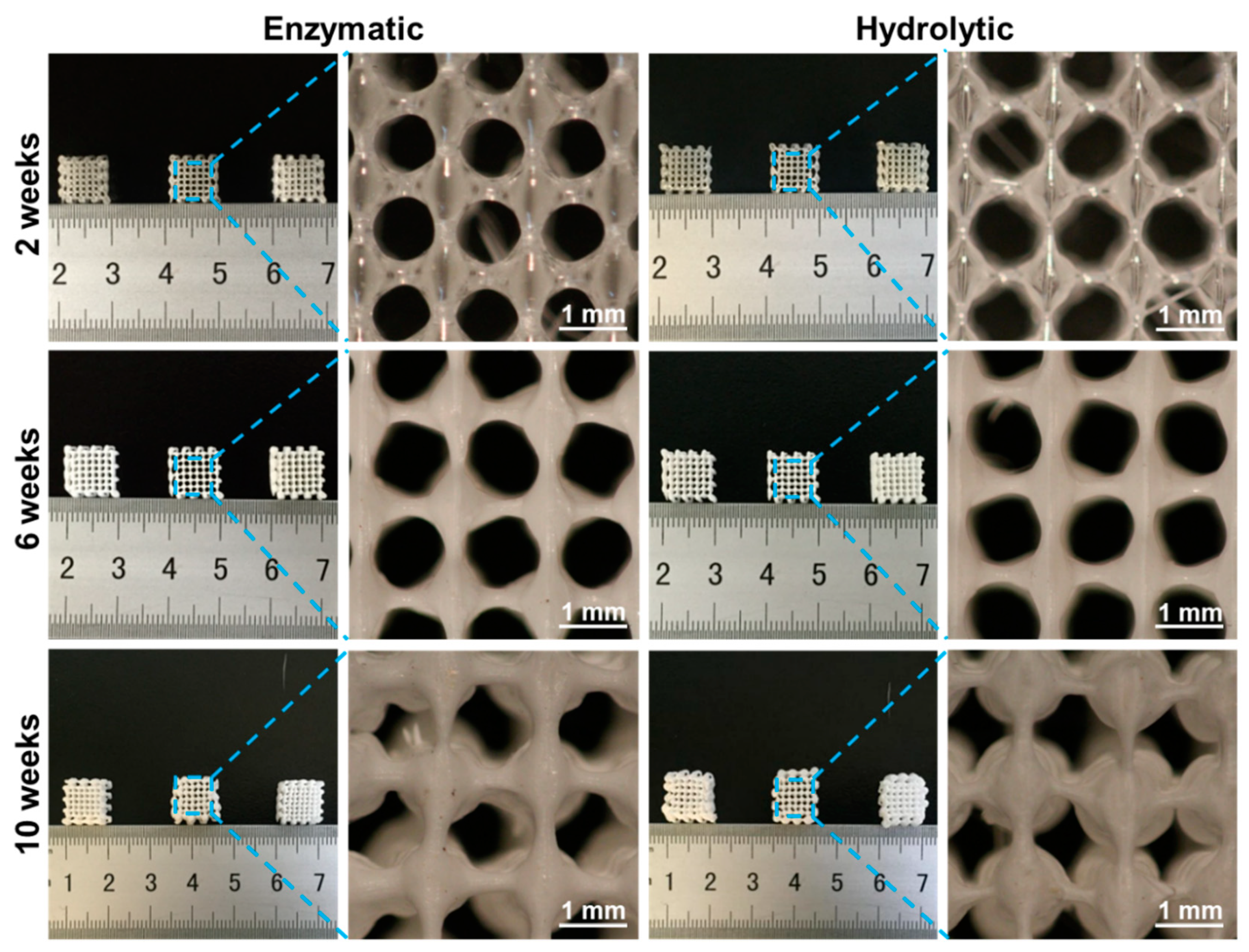
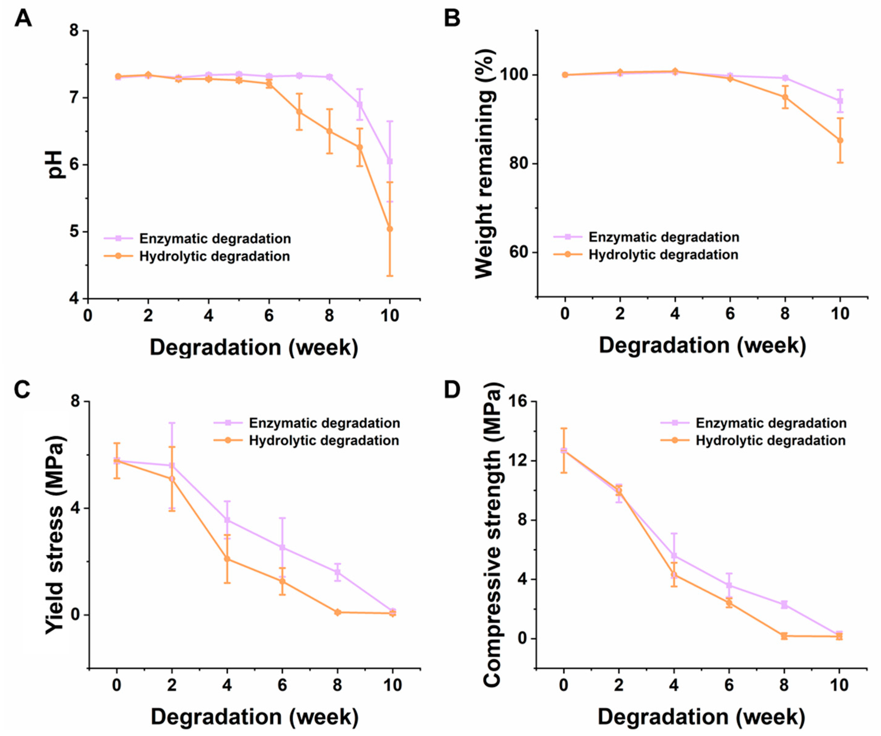
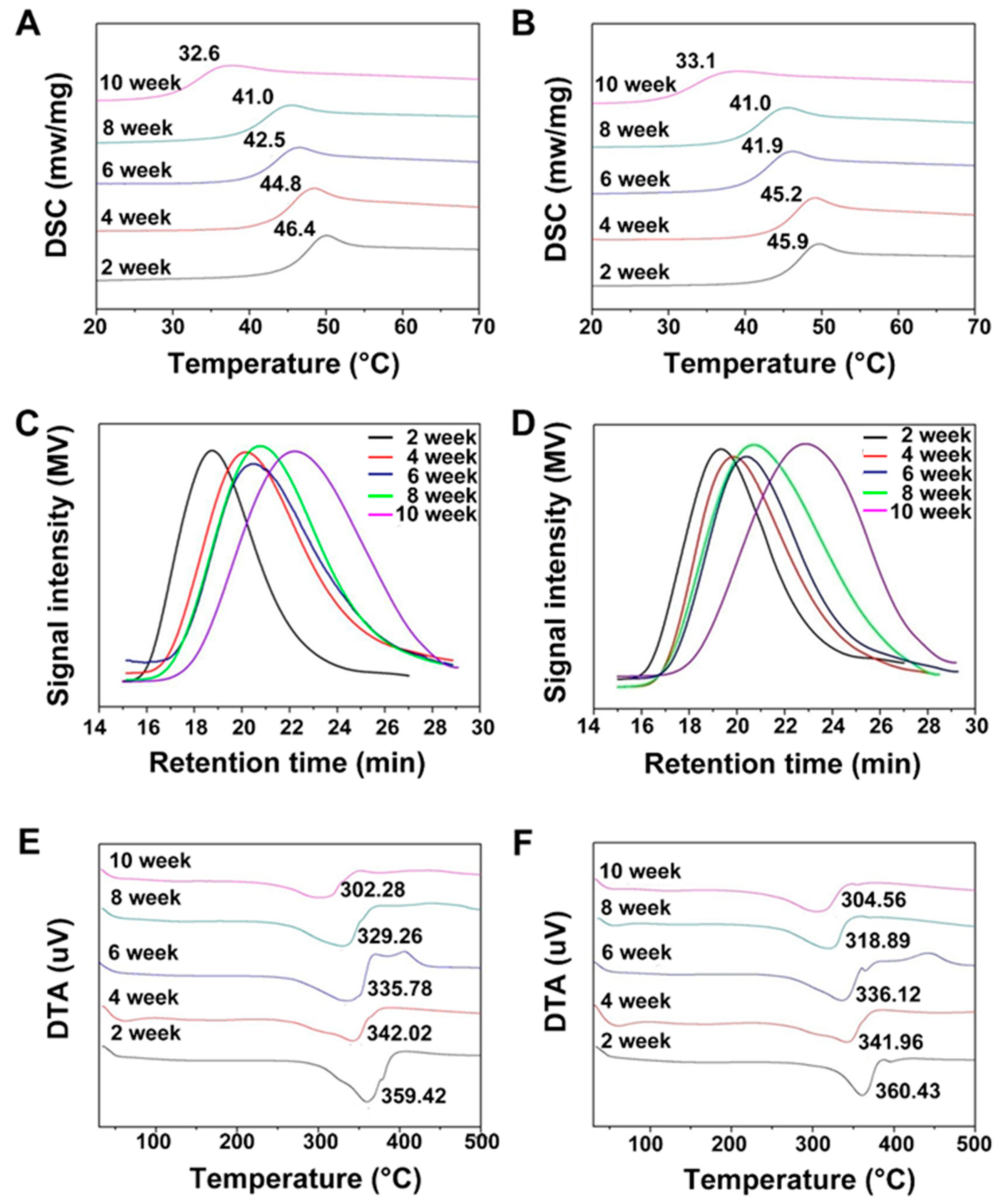
3.2. In Vitro Degradation of the PLGA Scaffolds
3.3. Bioefficacy of the PLGA Scaffolds
3.3.1. Cytotoxicity Test
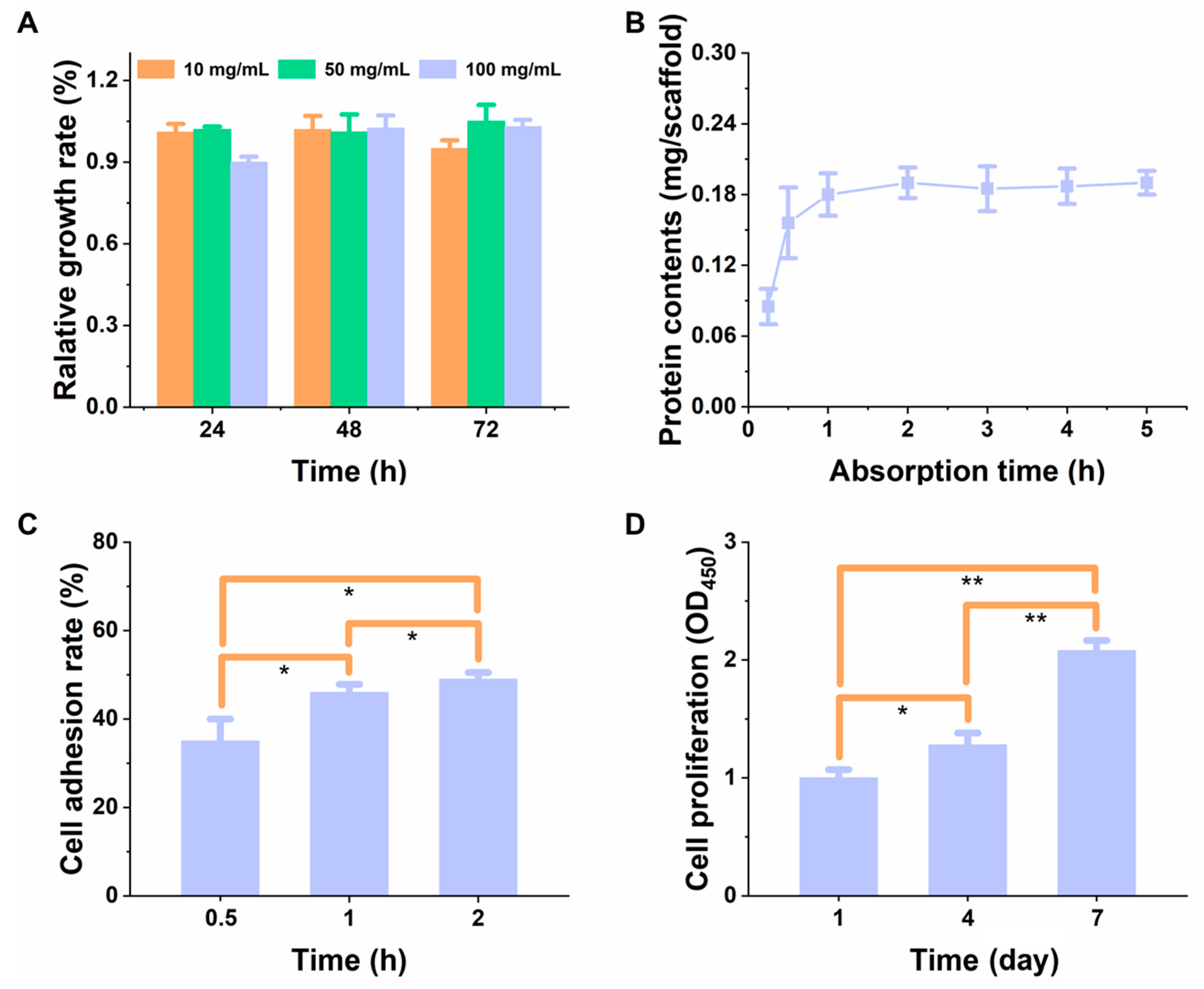
3.3.2. The Relative Proliferation Rate of Cells and Adsorption Kinetics of Protein
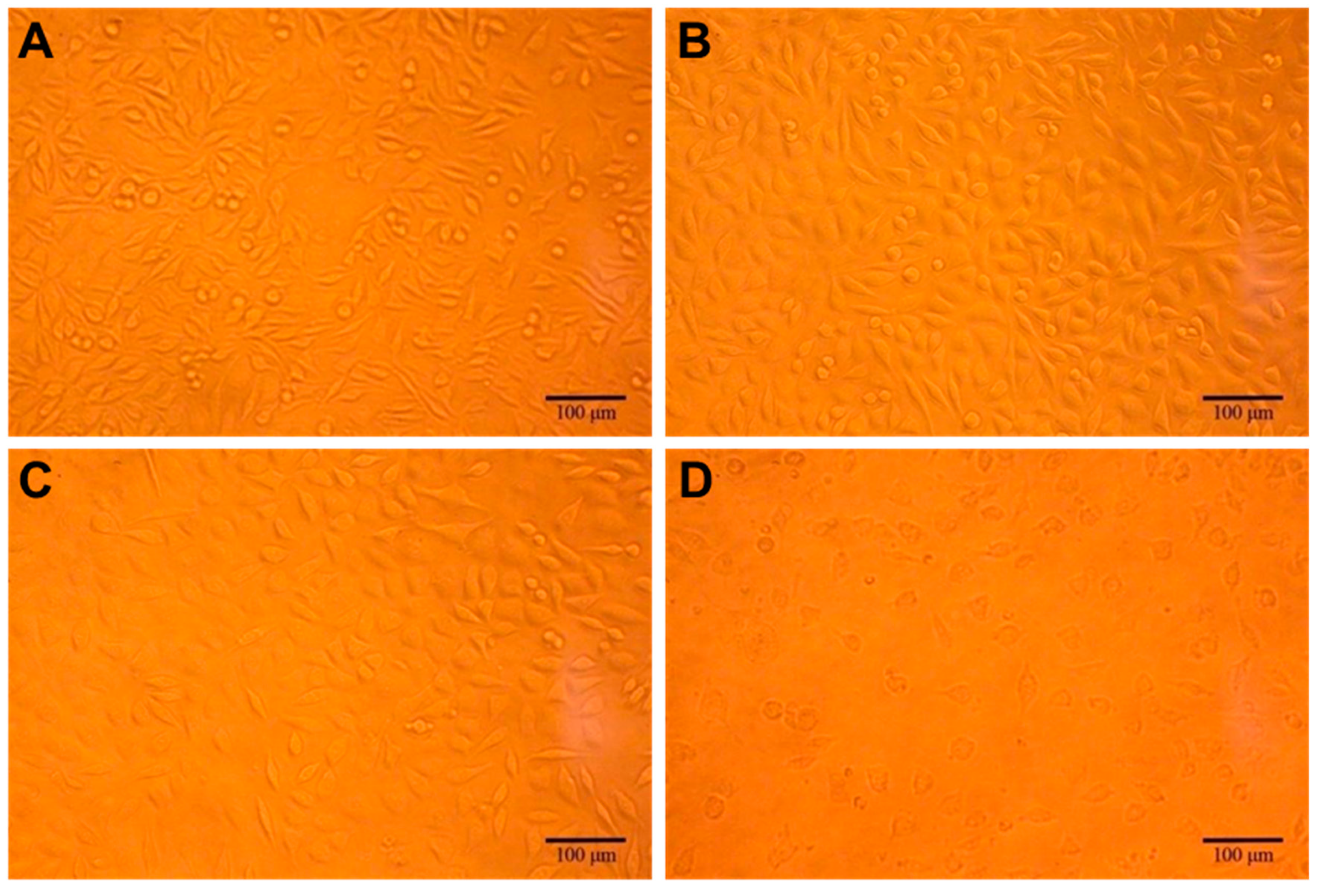
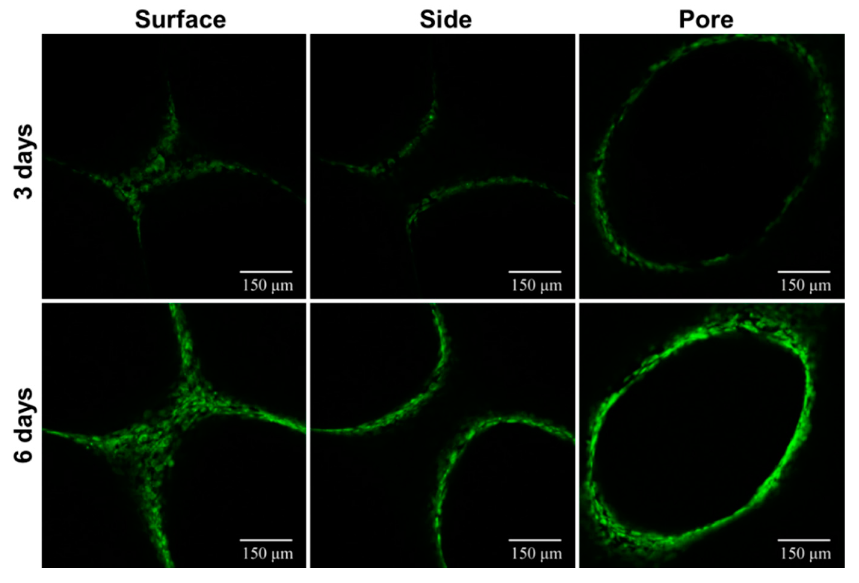
3.3.3. Cell Distribution Study
4. Conclusions
Author Contributions
Funding
Conflicts of Interest
References
- Murphy, S.V.; Atala, A. 3D bioprinting of tissues and organs. Nat. Biotechnol. 2014, 32, 773–785. [Google Scholar] [CrossRef] [PubMed]
- Kankala, R.K.; Zhu, K.; Sun, X.-N.; Liu, C.-G.; Wang, S.-B.; Chen, A.-Z. Cardiac tissue engineering on the nanoscale. ACS Biomater. Sci. Eng. 2018, 4, 800–818. [Google Scholar] [CrossRef]
- Kankala, R.K.; Zhu, K.; Li, J.; Wang, C.S.; Wang, S.B.; Chen, A.Z. Fabrication of arbitrary 3d components in cardiac surgery: From macro-, micro- to nanoscale. Biofabrication 2017, 9, 032002. [Google Scholar] [CrossRef] [PubMed]
- Dvir, T.; Timko, B.P.; Kohane, D.S.; Langer, R. Nanotechnological strategies for engineering complex tissues. Nat. Nanotechnol. 2011, 6, 13–22. [Google Scholar] [CrossRef] [PubMed]
- Singh, R.S.; Kaur, N.; Rana, V.; Kennedy, J.F. Recent insights on applications of pullulan in tissue engineering. Carbohydr. Polym. 2016, 153, 455–462. [Google Scholar] [CrossRef] [PubMed]
- Kankala, R.K.; Zhang, Y.S.; Wang, S.B.; Lee, C.H.; Chen, A.Z. Supercritical fluid technology: An emphasis on drug delivery and related biomedical applications. Adv. Healthc. Mater. 2017, 6, 1700433. [Google Scholar]
- Li, C.; Liu, D.; Zhang, Z.; Wang, G.; Xu, N. Triple point-mutants of hypoxia-inducible factor-1α accelerate in vivo angiogenesis in bone defect regions. Cell Biochem. Biophys. 2013, 67, 557–566. [Google Scholar] [CrossRef] [PubMed]
- Seebach, C.; Henrich, D.; Wilhelm, K.; Barker, J.H.; Marzi, I. Endothelial progenitor cells improve directly and indirectly early vascularization of mesenchymal stem cell-driven bone regeneration in a critical bone defect in rats. Cell Transpl. 2012, 21, 1667–1677. [Google Scholar] [CrossRef] [PubMed]
- Chen, B.Q.; Kankala, R.K.; Chen, A.Z.; Yang, D.Z.; Cheng, X.X.; Jiang, N.; Zhu, K.; Wang, S.B. Investigation of silk fibroin nanoparticle-decorated poly(l-lactic acid) composite scaffolds for osteoblast growth and differentiation. Int. J. Nanomed. 2017, 12, 1877–1890. [Google Scholar] [CrossRef] [PubMed]
- Han, Y.-H.; Kankala, R.; Wang, S.-B.; Chen, A.-Z. Leveraging engineering of indocyanine green-encapsulated polymeric nanocomposites for biomedical applications. Nanomaterials 2018, 8, 360. [Google Scholar] [CrossRef] [PubMed]
- Abdal-Hay, A.; Hamdy, A.S.; Khalil, K.A.; Ju, H.L. A novel simple in situ biomimetic and simultaneous deposition of bonelike apatite within biopolymer matrix as bone graft substitutes. Mater. Lett. 2014, 137, 260–264. [Google Scholar] [CrossRef]
- Kankala, R.K.; Lu, F.-J.; Liu, C.-G.; Zhang, S.-S.; Chen, A.-Z.; Wang, S.-B. Effect of icariin on engineered 3d-printed porous scaffolds for cartilage repair. Materials 2018, 11, 1390. [Google Scholar] [CrossRef] [PubMed]
- Li, F.; Wang, Z.; Dong, S.; Cai, Y.; Ni, Y.; Zhang, T.; Wang, L.; Zhou, Y. Bilayer poly(lactic-co-glycolic acid)/nano-hydroxyapatite membrane with barrier function and osteogenesis promotion for guided bone regeneration. Materials 2017, 10, 257. [Google Scholar]
- Chen, Y.; Xu, Z.; Smith, C.; Sankar, J. Recent advances on the development of magnesium alloys for biodegradable implants. Acta Biomater. 2014, 10, 4561–4573. [Google Scholar] [CrossRef] [PubMed]
- Okazaki, Y.; Rao, S.; Ito, Y.; Tateishi, T. Corrosion resistance, mechanical properties, corrosion fatigue strength and cytocompatibility of new ti alloys without al and v. Biomaterials 1998, 19, 1197–1215. [Google Scholar] [CrossRef]
- Piotrowski, B.; Baptista, A.A.; Patoor, E.; Bravetti, P.; Eberhardt, A.; Laheurte, P. Interaction of bone-dental implant with new ultra low modulus alloy using a numerical approach. Mater. Sci. Eng. C 2014, 38, 151–160. [Google Scholar] [CrossRef] [PubMed]
- Boskey, A.L.; Maresca, M.; Ullrich, W.; Doty, S.B.; Butler, W.T.; Prince, C.W. Osteopontin-hydroxyapatite interactions in vitro: Inhibition of hydroxyapatite formation and growth in a gelatin-gel. Bone Min. 1993, 22, 147–159. [Google Scholar] [CrossRef]
- Du, J.; Zou, Q.; Zuo, Y.; Li, Y. Cytocompatibility and osteogenesis evaluation of HA/GCPU composite as scaffolds for bone tissue engineering. Int. J. Surg. 2014, 12, 404–407. [Google Scholar] [CrossRef] [PubMed]
- Chun, K.W.; Yoo, H.S.; Yoon, J.J.; Park, T.G. Biodegradable PLGA microcarriers for injectable delivery of chondrocytes: Effect of surface modification on cell attachment and function. Biotechnol. Prog. 2010, 20, 1797–1801. [Google Scholar] [CrossRef] [PubMed]
- Cao, H.; Kuboyama, N. A biodegradable porous composite scaffold of PGA/β-TCP for bone tissue engineering. Bone 2010, 46, 386–395. [Google Scholar] [CrossRef] [PubMed]
- Mou, Z.L.; Duan, L.M.; Qi, X.N.; Zhang, Z.Q. Preparation of silk fibroin/collagen/hydroxyapatite composite scaffold by particulate leaching method. Mater. Lett. 2013, 105, 189–191. [Google Scholar] [CrossRef]
- Locs, J.; Zalite, V.; Berzina-Cimdina, L.; Sokolova, M. Ammonium hydrogen carbonate provided viscous slurry foaming—A novel technology for the preparation of porous ceramics. J. Eur. Ceram. Soc. 2013, 33, 3437–3443. [Google Scholar] [CrossRef]
- Sauceau, M.; Fages, J.; Common, A.; Nikitine, C.; Rodier, E. New challenges in polymer foaming: A review of extrusion processes assisted by supercritical carbon dioxide. Prog. Polym. Sci. 2011, 36, 749–766. [Google Scholar] [CrossRef]
- Khorasani, M.M.; Ghaffarian, S.R.; Goldansaz, S.H.; Mohammadi, N.; Babaie, A. Solid-state microcellular foaming of PE/PE composite systems, investigation on cellular structure and crystalline morphology. Compos. Sci. Technol. 2010, 70, 1942–1949. [Google Scholar] [CrossRef]
- Zhao, J.; Han, W.; Tu, M.; Huan, S.; Zeng, R.; Wu, H.; Cha, Z.; Zhou, C. Preparation and properties of biomimetic porous nanofibrous poly(l-lactide) scaffold with chitosan nanofiber network by a dual thermally induced phase separation technique. Mater. Sci. Eng. C 2012, 32, 1496–1502. [Google Scholar] [CrossRef] [PubMed]
- Xiong, Z.; Yan, Y.; Wang, S.; Zhang, R.; Zhang, C. Fabrication of porous scaffolds for bone tissue engineering via low-temperature deposition. Scr. Mater. 2002, 46, 771–776. [Google Scholar] [CrossRef]
- Hutmacher, D.W.; Sittinger, M.; Risbud, M.V. Scaffold-based tissue engineering: Rationale for computer-aided design and solid free-form fabrication systems. Trends Biotechnol. 2004, 22, 354–362. [Google Scholar] [CrossRef] [PubMed]
- Pereira, T.F.; Silva, M.A.C.; Oliveira, M.F.; Maia, I.A.; Silva, J.V.L.; Costa, M.F.; Thiré, R.M.S.M. Effect of process parameters on the properties of selective laser sintered poly(3-hydroxybutyrate) scaffolds for bone tissue engineering. Virtual Phys. Prototyp. 2012, 7, 275–285. [Google Scholar] [CrossRef]
- Bose, S.; Vahabzadeh, S.; Bandyopadhyay, A. Bone tissue engineering using 3d printing. Mater. Today 2013, 16, 496–504. [Google Scholar] [CrossRef]
- Leong, K.F.; Cheah, C.M.; Chua, C.K. Solid freeform fabrication of three-dimensional scaffolds for engineering replacement tissues and organs. Biomaterials 2003, 24, 2363–2378. [Google Scholar] [CrossRef]
- Yeong, W.Y.; Chua, C.K.; Leong, K.F.; Chandrasekaran, M. Rapid prototyping in tissue engineering: Challenges and potential. Trends Biotechnol. 2004, 22, 643–652. [Google Scholar] [CrossRef] [PubMed]
- Xu, M.; Li, Y.; Suo, H.; Yan, Y.; Liu, L.; Wang, Q.; Ge, Y.; Xu, Y. Fabricating a pearl/PLGA composite scaffold by the low-temperature deposition manufacturing technique for bone tissue engineering. Biofabrication 2010, 2, 025002. [Google Scholar] [CrossRef] [PubMed]
- Kim, J.Y.; Cho, D.W. Blended PCL/PLGA scaffold fabrication using multi-head deposition system. Microelectron. Eng. 2009, 86, 1447–1450. [Google Scholar] [CrossRef]
- Zhao, W.; Li, J.; Jin, K.; Liu, W.; Qiu, X.; Li, C. Fabrication of functional PLGA-based electrospun scaffolds and their applications in biomedical engineering. Mater. Sci. Eng. C 2016, 59, 1181–1194. [Google Scholar] [CrossRef] [PubMed]
- Kankala, R.K.; Xu, X.M.; Liu, C.G.; Chen, A.Z.; Wang, S.B. 3D-printing of microfibrous porous scaffolds based on hybrid approaches for bone tissue engineering. Polymers 2018, 10, 807. [Google Scholar] [CrossRef]
- Curran, J.M.; Chen, R.; Hunt, J.A. Controlling the phenotype and function of mesenchymal stem cells in vitro by adhesion to silane-modified clean glass surfaces. Biomaterials 2005, 26, 7057–7067. [Google Scholar] [CrossRef] [PubMed]
- Zein, I.; Hutmacher, D.W.; Tan, K.C.; Teoh, S.H. Fused deposition modeling of novel scaffold architectures for tissue engineering applications. Biomaterials 2002, 23, 1169–1185. [Google Scholar] [CrossRef]
- Shkarina, S.; Shkarin, R.; Weinhardt, V.; Melnik, E.; Vacun, G.; Kluger, P.; Loza, K.; Epple, M.; Ivlev, S.I.; Baumbach, T.; et al. 3D biodegradable scaffolds of polycaprolactone with silicate-containing hydroxyapatite microparticles for bone tissue engineering: High-resolution tomography and in vitro study. Sci. Rep. 2018, 8, 8907. [Google Scholar] [CrossRef] [PubMed]
- Wu, L.; Ding, J. In vitro degradation of three-dimensional porous poly(d,l-lactide-co-glycolide) scaffolds for tissue engineering. Biomaterials 2004, 25, 5821–5830. [Google Scholar] [CrossRef] [PubMed]
- Farzadi, A.; Solati-Hashjin, M.; Asadi-Eydivand, M.; Abu Osman, N.A. Effect of layer thickness and printing orientation on mechanical properties and dimensional accuracy of 3d printed porous samples for bone tissue engineering. PLoS ONE 2014, 9, e108252. [Google Scholar] [CrossRef] [PubMed]
- Gerhart, T.N.; Miller, R.L.; Kleshinski, S.J.; Hayes, W.C. In vitro characterization and biomechanical optimization of a biodegradable particulate composite bone cement. J. Biomed. Mater. Res. Part A 2010, 22, 1071–1082. [Google Scholar] [CrossRef] [PubMed]
- Zhen, P.; Ding, J. Poly(lactide-co-glycolide) porous scaffolds for tissue engineering and regenerative medicine. Interface Focus A Theme Suppl. J. R. Soc. Interface 2012, 2, 366–377. [Google Scholar]
- Lam, C.X.F.; Mo, X.M.; Teoh, S.H.; Hutmacher, D.W. Scaffold development using 3d printing with a starch-based polymer. Mater. Sci. Eng. C 2002, 20, 49–56. [Google Scholar] [CrossRef]
- Goldstein, S.A. The mechanical properties of trabecular bone: Dependence on anatomic location and function. J. Biomech. 1987, 20, 1055–1061. [Google Scholar] [CrossRef]
- Zhang, J.; Wu, L.; Jing, D.; Ding, J. A comparative study of porous scaffolds with cubic and spherical macropores. Polymer 2005, 46, 4979–4985. [Google Scholar] [CrossRef]
- Currey, J.D. The effect of porosity and mineral content on the young’s modulus of elasticity of compact bone. J. Biomech. 1988, 21, 131–139. [Google Scholar] [CrossRef]
- Sonnenschein, M.F. Porosity-dependent young’s modulus of membranes from polyetherether ketone. J. Polym. Sci. Part B Polym. Phys. 2003, 41, 1168–1174. [Google Scholar] [CrossRef]
- Loo, S.C.J.; Ooi, C.P.; Yin, C.F.B. Radiation effects on poly(lactide-co-glycolide) (PLGA) and poly(l-lactide) (PLLA). Polym. Degrad. Stab. 2004, 83, 259–265. [Google Scholar] [CrossRef]
- Saito, E.; Liu, Y.; Migneco, F.; Hollister, S.J. Strut size and surface area effects on long-term in vivo degradation in computer designed poly(l-lactic acid) three-dimensional porous scaffolds. Acta Biomater. 2012, 8, 2568–2577. [Google Scholar] [CrossRef] [PubMed]
- Bergsma, J.E.; de Bruijn, W.C.; Rozema, F.R.; Bos, R.R.; Boering, G. Late degradation tissue response to poly(l-lactide) bone plates and screws. Biomaterials 1995, 16, 25–31. [Google Scholar] [CrossRef]
- Park, T.G. Degradation of poly(lactic-co-glycolic acid) microspheres: Effect of copolymer composition. Biomaterials 1995, 16, 1123–1130. [Google Scholar] [CrossRef]
- Liao, K.R.; Zhao, J.H.; Luo, B.H.; Lu, Z.J. Studies of polylactide/hydroxylapatite composites. Iii. The in vitro degradation behavior of poly(d,l-lactide)/hydroxylapatite composites. Acta Sci. Nat. Univ. Sunyatseni 2001, 1, 44–47. [Google Scholar]
- Middleton, J.C.; Tipton, A.J. Synthetic biodegradable polymers as orthopedic devices. Biomaterials 2000, 21, 2335–2346. [Google Scholar] [CrossRef]
- Minkim, J.; Seo, K.S.; Yong, K.J.; Hai, B.L.; Yong, S.K.; Khang, G. Co-effect of aqueous solubility of drugs and glycolide monomer on in vitro release rates from poly(d,l-lactide- co-glycolide) discs and polymer degradation. J. Biomater. Sci. Polym. Ed. 2005, 16, 991–1007. [Google Scholar]
- Birnbaum, D.T.; Brannonpeppas, L. Molecular weight distribution changes during degradation and release of PLGA nanoparticles containing epirubicin HCL. J. Biomater. Sci. Polym. Ed. 2003, 14, 87–102. [Google Scholar] [CrossRef] [PubMed]
- Kim, B.S.; Mooney, D.J. Engineering smooth muscle tissue with a predefined structure. J. Biomed. Mater. Res. Part B Appl. Biomater. 2015, 41, 322–332. [Google Scholar] [CrossRef]
- Klose, D.; Delplace, C.; Siepmann, J. Unintended potential impact of perfect sink conditions on PLGA degradation in microparticles. Int. J. Pharm. 2011, 404, 75–82. [Google Scholar] [CrossRef] [PubMed]
- Cai, Q.; Shi, G.; Bei, J.; Wang, S. Enzymatic degradation behavior and mechanism of poly(lactide-co-glycolide) foams by trypsin. Biomaterials 2003, 24, 629–638. [Google Scholar] [CrossRef]
- Hiraguchi, Y.; Nagahashi, K.; Shibayama, T.; Hayashi, T.; Yano, T.A.; Kushiro, K.; Takai, M. Effect of the distribution of adsorbed proteins on cellular adhesion behaviors using surfaces of nanoscale phase-reversed amphiphilic block copolymers. Acta Biomater. 2014, 10, 2988–2995. [Google Scholar] [CrossRef] [PubMed]
- Takahashi, Y.; Yamamoto, M.; Tabata, Y. Design of an osteoinductive biodegradable cell scaffold based on controlled release technology of bone morphogenetic protein. Israel J. Chem. 2010, 45, 465–475. [Google Scholar] [CrossRef]
- Linden, R. The biological function of the prion protein: A cell surface scaffold of signaling modules. Front. Mol. Neurosci. 2017, 10, 77. [Google Scholar] [CrossRef] [PubMed]


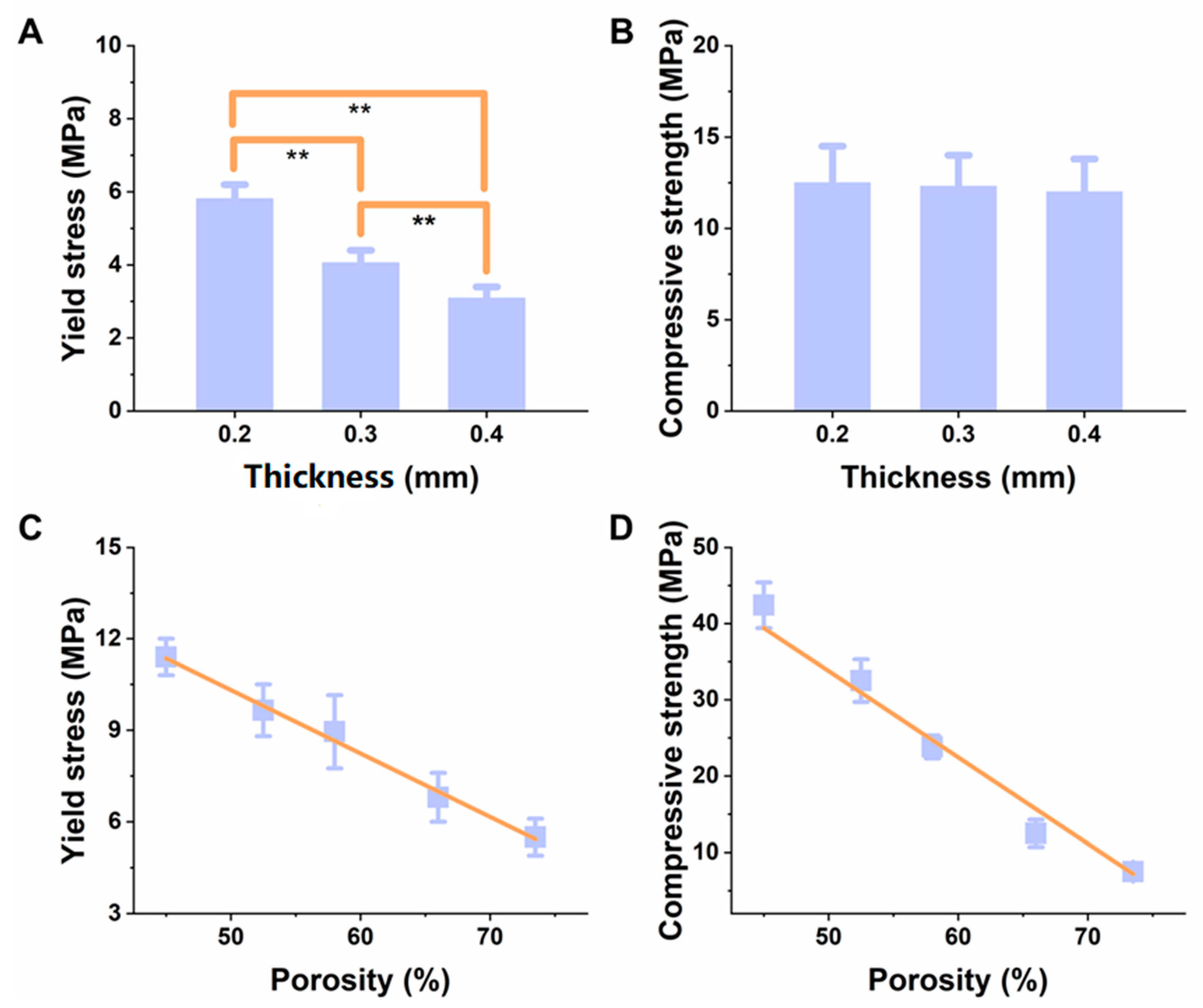
| Nozzle Inner Diameter (mm) | Temperature (°C) | Pressure (MPa) | Velocity (mm/s) | Layer Thickness (mm) | Filling Distance (mm) |
|---|---|---|---|---|---|
| 0.2 | 215 ± 2 | 0.15–0.3 | 8–11 | 0.17 | 0.8–1.1 |
| 0.3 | 205 ± 2 | 0.1–0.25 | 8–11 | 0.25 | 0.8–1.2 |
| 0.4 | 197 ± 2 | 0.08–0.2 | 10–12 | 0.33 | 0.9–1.2 |
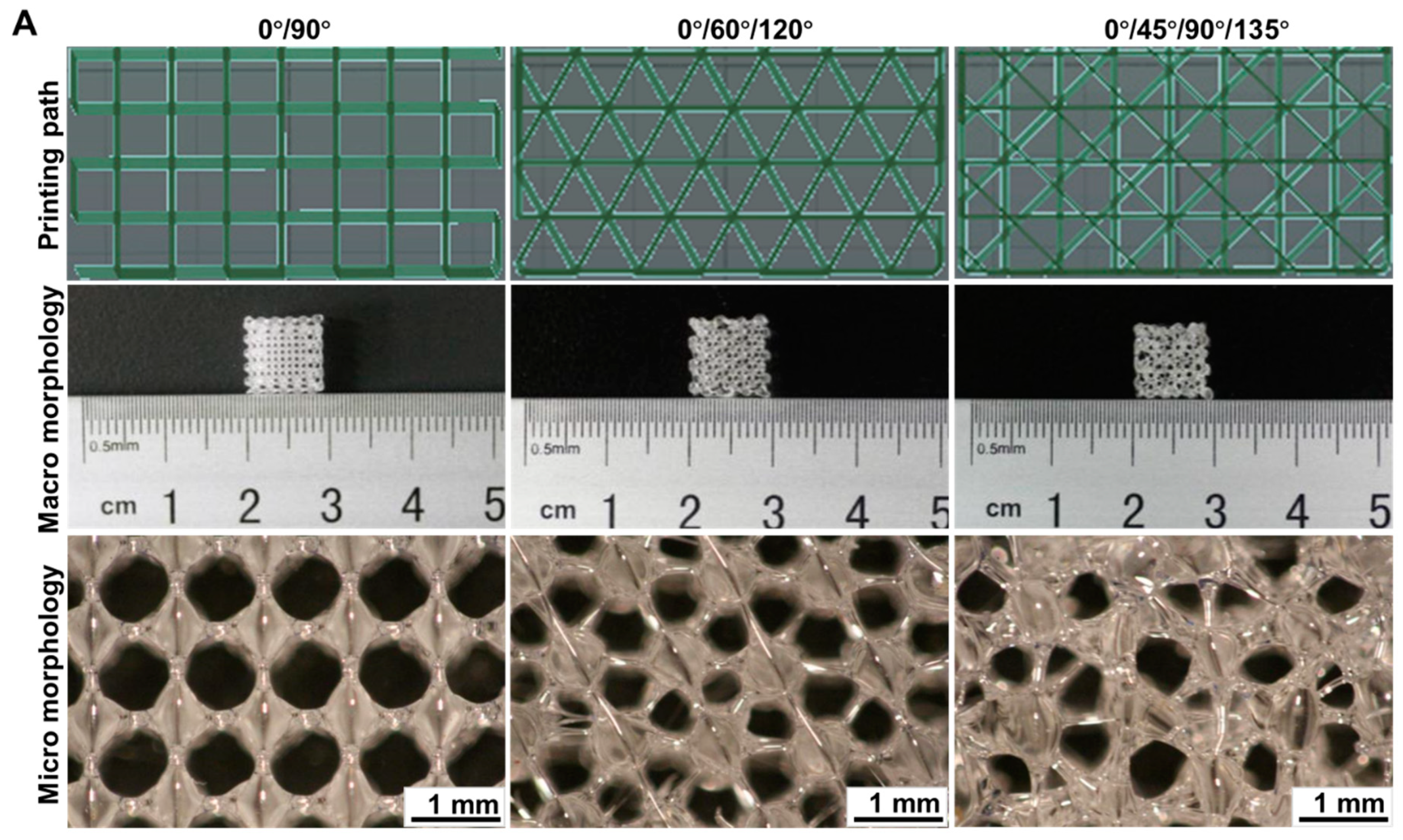
| Structures | 0°/90° | 0°/60°/120° | 0°/45°/90°/135° |
|---|---|---|---|
| Pore size (μm) | 575–742 | 584–775 | 443–761 |
| Wire diameter (μm) | 221–342 | 205–268 | 205–322 |
© 2018 by the authors. Licensee MDPI, Basel, Switzerland. This article is an open access article distributed under the terms and conditions of the Creative Commons Attribution (CC BY) license (http://creativecommons.org/licenses/by/4.0/).
Share and Cite
Liu, C.-G.; Zeng, Y.-T.; Kankala, R.K.; Zhang, S.-S.; Chen, A.-Z.; Wang, S.-B. Characterization and Preliminary Biological Evaluation of 3D-Printed Porous Scaffolds for Engineering Bone Tissues. Materials 2018, 11, 1832. https://doi.org/10.3390/ma11101832
Liu C-G, Zeng Y-T, Kankala RK, Zhang S-S, Chen A-Z, Wang S-B. Characterization and Preliminary Biological Evaluation of 3D-Printed Porous Scaffolds for Engineering Bone Tissues. Materials. 2018; 11(10):1832. https://doi.org/10.3390/ma11101832
Chicago/Turabian StyleLiu, Chen-Guang, Yu-Ting Zeng, Ranjith Kumar Kankala, Shan-Shan Zhang, Ai-Zheng Chen, and Shi-Bin Wang. 2018. "Characterization and Preliminary Biological Evaluation of 3D-Printed Porous Scaffolds for Engineering Bone Tissues" Materials 11, no. 10: 1832. https://doi.org/10.3390/ma11101832
APA StyleLiu, C.-G., Zeng, Y.-T., Kankala, R. K., Zhang, S.-S., Chen, A.-Z., & Wang, S.-B. (2018). Characterization and Preliminary Biological Evaluation of 3D-Printed Porous Scaffolds for Engineering Bone Tissues. Materials, 11(10), 1832. https://doi.org/10.3390/ma11101832