Article

Thermoelectric Mixed Thick-/Thin Film Microgenerators Based on Constantan/Silver

by
Mirosław Gierczak
*,
Joanna Prażmowska-Czajka
and
Andrzej Dziedzic
Faculty of Microsystem Electronics and Photonics, Wrocław University of Science and Technology, Janiszewskiego 11/17, 50-372 Wrocław, Poland
*
Author to whom correspondence should be addressed.
Materials 2018, 11(1), 115; https://doi.org/10.3390/ma11010115
Submission received: 18 December 2017 / Revised: 5 January 2018 / Accepted: 8 January 2018 / Published: 12 January 2018

Abstract

:
This paper describes the design, manufacturing and characterization of newly developed mixed thick-/thin film thermoelectric microgenerators based on magnetron sputtered constantan (copper-nickel alloy) and screen-printed silver layers. The thermoelectric microgenerator consists of sixteen thermocouples made on a 34.2 × 27.5 × 0.25 mm3 alumina substrate. One of thermocouple arms was made of magnetron-sputtered constantan (Cu-Ni alloy), the second was a Ag-based screen-printed film. The length of each thermocouple arm was equal to 27 mm, and their width 0.3 mm. The distance between the arms was equal to 0.3 mm. In the first step, a pattern mask with thermocouples was designed and fabricated. Then, a constantan layer was magnetron sputtered over the whole substrate, and a photolithography process was used to prepare the first thermocouple arms. The second arms were screen-printed onto the substrate using a low-temperature silver paste (Heraeus C8829A or ElectroScience Laboratories ESL 599-E). To avoid oxidation of constantan, they were fired in a belt furnace in a nitrogen atmosphere at 550/450 °C peak firing temperature. Thermoelectric and electrical measurements were performed using the self-made measuring system. Two pyrometers included into the system were used for temperature measurement of hot and cold junctions. The estimated Seebeck coefficient, α was from the range 35 − 41 µV/K, whereas the total internal resistances R were between 250 and 3200 ohms, depending on magnetron sputtering time and kind of silver ink (the resistance of a single thermocouple was between 15.5 and 200 ohms).

1. Introduction

Small and cost-effective thermoelectric microgenerators based on the Seebeck effect in semiconductors or metals usually convert waste thermal energy directly into useable electrical energy. They are potential energy sources for low-power autonomous microsystems. The most commonly investigated thermoelectric materials, sensors and microgenerators are based on metals, materials based on silicon and/or germanium (SiGe, silicides, germanides), Bi2Te3, materials based on elements from group V (As, Sb, Bi) and group VI (Se, Te), PGEC materials (phonon-glass, electron-crystal), e.g., skutterudites, intermetallic clathrates or half-Heusler alloys), TAGS (Te-Ag-Ge-Sb) or LAST (Pb-Sb-Ag-Te) systems, and oxides with metallic conductivity or Thermoelectric Materials Functionally Graded (TMFG) [1,2,3,4,5,6,7,8,9,10]. It should be noted that some of the previously reported highly efficient thermoelectric compositions (mostly semiconductive ones, such as half-Heuslers, lead telluride and germanium telluride) can be used for power-generation applications [11].
Various methods are used for the fabrication of modern thermoelectric microsensors (e.g., temperature [12,13], heat flux [14,15], thermal insolation [15,16,17], laser power [1,18,19], Seebeck nanoantennas for solar energy harvesting [20] or calorimeters [21]) and microgenerators [1,2,3,4,5,6,7,10,22,23,24,25,26,27]—classical semiconductor technology and silicon micromachining [1], volume micromachining [1,5,6,9,25] (where, for example, vapor phase soldering is used to improve solder joint quality and reliability of the various microgenerator parts [28]), plasma spraying and laser patterning [29,30], thin-film deposition (evaporation, magnetron sputtering, electrochemical deposition) [3,8,24,25,31], thick-film technology (planar, 3D, on flexible substrates, alumina or LTCC ones) [2,4,6,7,10,11,12,13,22,26,32,33,34,35].
In general, thick-film technology is cheaper than thin-film technology, but so far, the largest Seebeck coefficient achieved for screen-printed metallic films was equal to 24 µV/K (Ag/Ni system [4,18]). On the other hand, mixed (thick/thin) film microgenerators fabricated and investigated at the Wrocław University of Science and Technology, where one arm was made from a screen-printed Ag- or Ni-based metallic film and the second one was made from magnetron-sputtered germanium-doped films [18,36,37,38], had a larger effective Seebeck coefficient, but simultaneously exhibited a much larger internal resistance, causing a lower power output compared to thick-film metallic microgenerators.
This paper presents the design, fabrication and characterization of newly developed, cost-effective thermoelectric microgenerators. The whole thermopile is based on metallic films, realized in mixed (hybrid) technology; this means that both arms are made from metallic layers. The constantan (copper-nickel alloy) arms were fabricated using thin-film technology, whereas the silver arms were prepared using standard thick-film technology. The test structures were realized on 24 alumina (96% Al2O3) substrates with a length of 34.2 mm, width of 27.5 and thickness of 0.25 mm. Sixteen thermocouples were performed on the surface of each substrate. Fabrication of the test structures can be divided into several steps: magnetron sputtering, photolithography and etching process of the constantan layer [39], and screen-printing and firing of the Ag-based film.
The thermoelectric force as a function of the temperature difference between hot and cold junctions as well as internal resistance was measured for microgenerators differing by the thickness of the magnetron-sputtered constantan layer and the kind of silver film. Measurements of structures were performed on the self-made automatic system for characterization of thermoelectric microgenerators, consisting of two pyrometers, the heating-cooling module, computer, measuring table, DC power supply and data acquisition unit [40].
This paper also presents the results of geometrical measurements, and shows total internal resistance and generated thermoelectric force as a function of temperature difference, as well as changes of the Seebeck coefficient (α), internal resistance (R) and Power Factor (PF) after long-term thermal exposure (it is well known that high temperature has a negative effect on most materials). The obtained results are very interesting and promising.

2. Materials and Methods
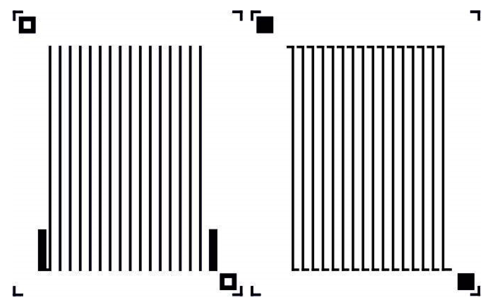
2.1. Design

The design of the masks for the microgenerator is shown in Figure 1. The width of the paths and the distance between them is 300 µm, and the length is 27 mm (the length of one path is equal to 90 squares—in the future, it will be possible to reduce the planar dimensions of the microgenerator, in particular the length of its arms; this should result in a decrease in the internal resistance of the thermopile). The mask pattern for silver paths with pads is shown on the left side, whereas the mask for the constantan (copper-nickel alloy) arms is presented on the right side.
The silver mask pattern was used to create the appropriate screen, while the mask pattern for the constantan (Cu-Ni alloy) was used in the photolithography process.

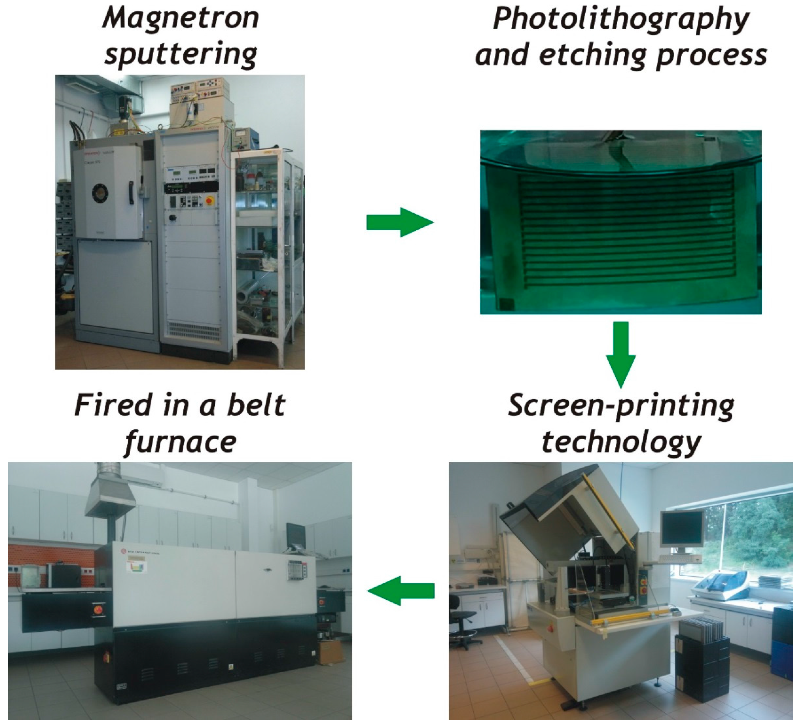
2.2. Fabrication of Test Structures
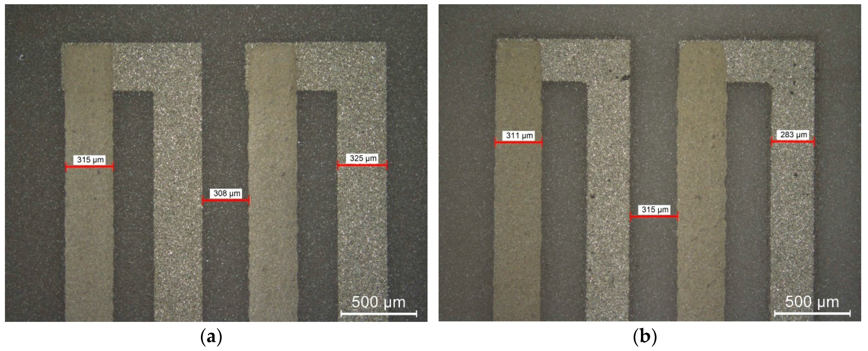
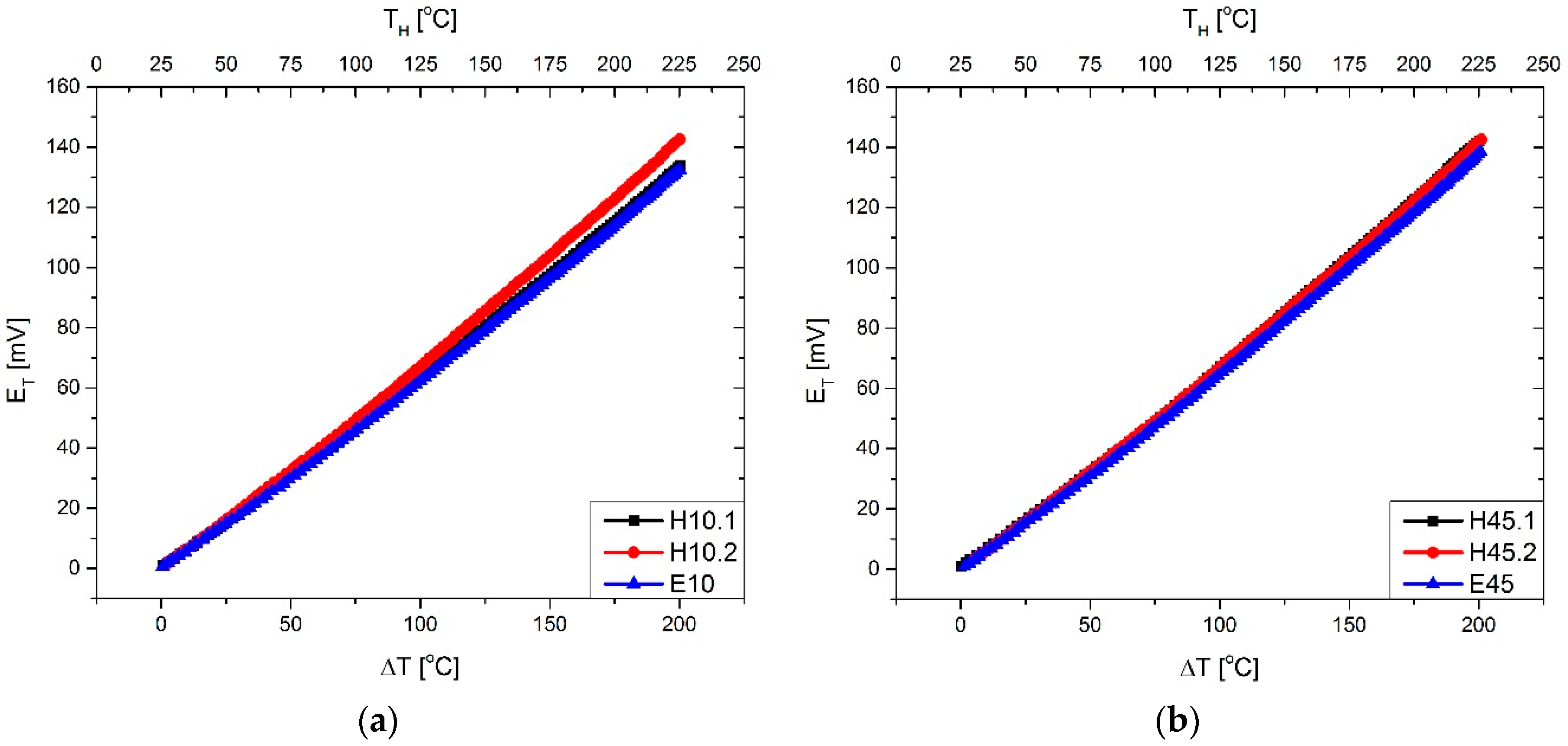
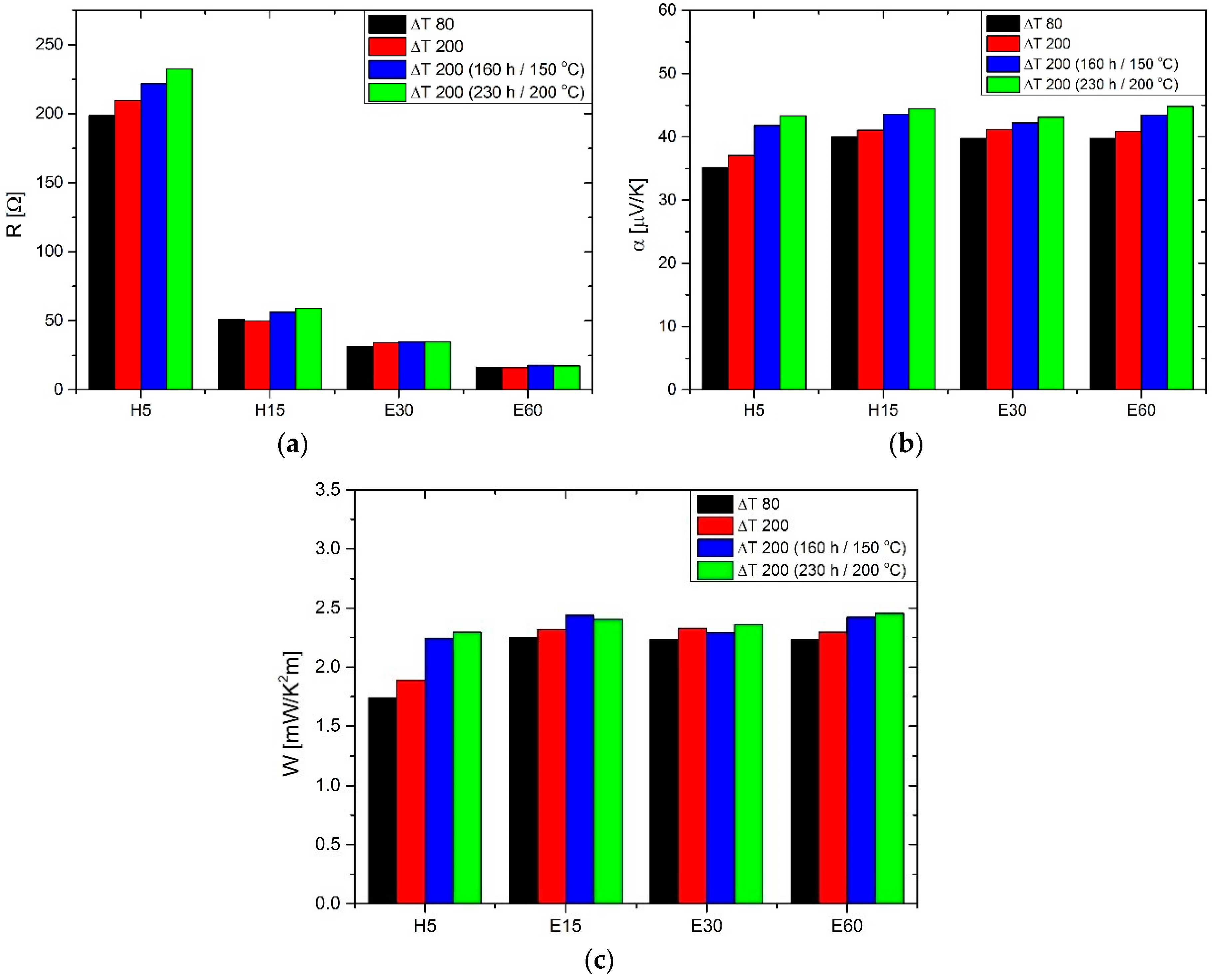
Twenty-four alumina substrates with dimensions of 34.2 × 27.5 × 0.25 mm3 were chemically cleaned and degreased in the first step. Next, the constantan layer was magnetron-sputtered onto the entire substrates. The thickness of these layers was dependent on sputtering time. There were six processes, with sputtering times of 5, 10, 15, 30, 45 and 60 min, respectively.
In the next step, a photolithography process was performed for all structures to make the first thermocouple arms. The etching solution used in this process consisted of 50 mL HNO3, 25 mL CH3COOH and 25 mL of deionized water (for 100 mL solution) [39]. Depending on the thickness of the layer, the etching time varied from about 30 s (for a sputtering time of 5 min) to about 7 min (for a magnetron sputtering time of 60 min).
Then, the second arms of the thermopile were made of Ag-based ink using screen-printing technology. Low-temperature cermet silver inks—Heraeus C8829A (Heraeus, Phoenixville, PA, USA) and ESL 599-E (ESL, King of Prussia, PA, USA) were applied. These films, after printing and drying, were fired in a belt furnace in a nitrogen atmosphere for a 60 min firing cycle with 550 °C peak firing temperature for the Heraeus ink and 450 °C for the ESL one (please note that according to manufacturers’ data sheets, these inks are recommended for air firing). The method of fabrication of the thermoelectric microgenerator is shown in Figure 2.

3. Results

Firstly, measurements of the geometry (path width and thickness) of the constantan and silver-based layer were made. The width of the paths and the distance between them was measured with an optical microscope (Leica Microsystems, Wetzlar, Germany), whereas an optical profilometer (Taylor Hobson, Leicester, UK) was applied for thickness measurements. The results for constantan films are collected in Table 1. Moreover, the chosen microscopic pictures of the structure, together with the path widths and the distance between them, are shown in Figure 3.
It can be seen that the increase of magnetron sputtering time leads to the increase of layer thickness. This, in turn, increases the time needed to etch the correct pattern of constantan arms. This process is accompanied by undercuts, and as a result, the increase in thickness of the constantan layer leads to the width decrease of the tracks made from this material and the same the gap between the thermopile arms is increased. The width of screen-printed silver-based film is almost constant within a range of 310–315 µm, whereas its thickness tAg is equal to about 9.5 μm.
In the rest of this article, the structures will be marked as follows: letter H means a path made from Heraeus C8829A paste, while letter E indicates ones made from ESL 599-E composition. The number before the dot refers to the time of constantan sputtering, and the number after the dot to the sample number.
Then, the values of the total internal resistance (R) of the structures were measured at room temperature. The results are presented in Table 2. The resistance decreased with increasing sputtering time of the constantan layer, and was almost independent on the kind of silver film. The total internal resistance of the thermopile (R) is the sum of the resistance of the constantan (RCu-Ni) and silver (RAg) tracks, as well as the resistance of the constantan/silver junctions (Rj). It can be assumed that the resistance of the silver paths and resistance of the constantan/silver junctions are constant. Moreover, it can be assumed that Rj << RAg. Thus, the systematic decrease in thermopile resistance is connected with resistance decrease of the constantan paths associated with the increase in their thickness.
Because
R = R C u N i + R A g + R j R C u N i + R A g = ρ C u N i t C u N i × n C u N i + ρ A g t A g × n A g
and, according to the mask pattern shown in Figure 1, n C u N i 1489 , whereas n A g 1441 , we can estimate that ρ A g 2.85 × 10 8 Ω·m, while ρ C u N i is from the range between 5.2 × 10 7 and 8.5 × 10 7 Ω·m.
Thermoelectric measurements (thermoelectric force vs. temperature difference between hot and cold junction) were performed by means of a self-made measuring system [40]. Two pyrometers included in the system were used for the temperature measurement of hot and cold junctions. The chosen results are shown in Figure 4.
For each measurement, a linear regression analysis was carried out, and Seebeck coefficients were calculated for a single thermocouple. The results are collected in Table 3.
It can be seen that in the case of the thinnest (submicron) constantan film, the Seebeck coefficient was slightly lower, and that the use of Heraeus silver ink in the thermopile leads to a slightly higher value of this parameter than for film made of ESL paste.
Knowledge of Seebeck coefficient (α) and resistivity (ρ) permits the calculation of Power Factor (PF). In the case of thermopiles consisting of constantan and silver arms, it can be calculated from the following formula:
P F = α 2 ( ρ C u N i + ρ A g )
Long-term thermal exposure was performed for all structures. In practically all cases, an increase in Seebeck coefficient, internal thermopile resistance and Power Factor was observed. Larger relative changes were noticed for structures with shorter magnetron sputtering time (thinner layer) of constantan. It should be noted that, despite the initial differences, the values of the Seebeck coefficient and the Power Factor after the post-process thermal aging became very close to one another. This indicates the homogenization of the internal structure of the thermopiles. Figure 5 shows the results for the selected structures. The initial measurements of the structures carried out for the temperature difference 80 °C is marked in the graphs as ΔT 80, while for a temperature difference of 200 °C—ΔT 200. The next two marks refer to the measurements after thermal exposure—first for 160 h at 150 °C and next for 230 h at 200 °C.

4. Discussion

This paper describes the design, fabrication and characterization of newly developed, cost-effective thermoelectric microgenerators based on magnetron-sputtered constantan (copper-nickel alloy) and screen-printed silver layers. The average value of the Seebeck coefficients calculated for the manufactured structures were in the range 35–41 µV/K—larger values were obtained for thicker films of constantan. The received value of the Seebeck coefficient is similar to the parameters of Cu-constantan or Ag-constantan wire thermocouples. After several stages of thermal aging, the Seebeck coefficient increased to a level of about 44–45 μV/K, regardless of the initial thickness of the constantan film.
Geometrical measurements of the width of paths and the distance between them showed very similar results to the designed values.
The largest generated thermoelectric force was produced by the structure H45, and was about 143 mV at a temperature difference of around 200 °C.
These results are very promising and the investigations are ongoing.

Acknowledgments

This work was supported by the National Science Center (Poland), Grant 2014/13/B/ST7/01634 (project FALCON).

Author Contributions

Mirosław Gierczak and Andrzej Dziedzic conceived and designed the experiments, analyzed the data and together wrote the paper; Mirosław Gierczak moreover designed and manufactured of structures (magnetron sputtering, etching process, screen-printing technology and fired in a belt furnace), Joanna Prażmowska-Czajka performed photolithography process.

Conflicts of Interest

The authors declare no conflict of interest.

References

  1. Brand, O.; Fedder, G.K.; Hierold, C.; Korvink, J.G.; Tabata, O. Thermoelectrics Energy Conversion, Basic Concepts and Device Applications; Pineda, D.D., Rezania, A., Eds.; Wiley-VCH: Weinheim, Germany, 2017. [Google Scholar]
  2. Ohta, T.; Kajikawa, T.; Kumashiro, Y. Characteristics of (Bi,Sb)2(Te,Se)3-based thick-film thermoelectric elements for power generation. Electr. Eng. Jpn. 1990, 110, 213–219. [Google Scholar] [CrossRef]
  3. Castaño, E.; Revuelto, E.; Martin, M.C.; Garcia-Alonso, A.; Gracia, F.J. Metallic thin-film thermocouple for thermoelectric microgenerators. Sens. Actuators A 1997, 60, 65–67. [Google Scholar] [CrossRef]
  4. Markowski, P.; Dziedzic, A. Planar and three-dimensional thick-film thermoelectric microgenerators. Microelectron. Reliab. 2008, 48, 890–896. [Google Scholar] [CrossRef]
  5. Koumoto, K.; Funahashi, R.; Guilmeau, E.; Miyazaki, Y.; Weindenkaff, A.; Wang, Y.; Wan, C. Thermoelectric ceramics for energy harvesting. J. Am. Ceram. Soc. 2013, 96, 1–23. [Google Scholar] [CrossRef]
  6. Rudež, R.; Markowski, P.; Presečnik, M.; Košir, M.; Dziedzic, A.; Bernik, S. Development of thick-film thermoelectric microgenerators based on p-type Ca3Co4O9 and n-type (ZnO)5∙In2O3 legs. Ceram. Int. 2015, 41, 13201–13209. [Google Scholar] [CrossRef]
  7. Dorey, R.A. Integrated powder-based thick films for thermoelectric, pyroelectric and piezoelectric energy harvesting devices. IEEE Sens. J. 2014, 14, 2177–2184. [Google Scholar] [CrossRef]
  8. Markowski, P.; Prociów, E.; Urbaniak, Ł. Thermoelectric properties of thin-film germanium-based layers. Microelectron. Int. 2015, 32, 115–121. [Google Scholar] [CrossRef]
  9. Xu, Y.; Qu, X.; Lu, S.; Bai, L.; Niu, L. Influence of external magnetic field on microstructure and electrical transport properties of Ca3−xLaxCo4O9+δ ceramics. Ceram. Int. 2016, 42, 11404–11410. [Google Scholar] [CrossRef]
  10. Orrill, M.; LeBlanc, S. Printed thermoelectric materials and devices; fabrication techniques, advantages and challenges. J. Appl. Polym. Sci. 2017, 133. [Google Scholar] [CrossRef]
  11. Appel, O.; Zilber, T.; Kalabukhov, S.; Beeri, O.; Gelbstein, Y. Morphological effects on the thermoelectric properties of Ti0.3Zr0.35Hf0.35Ni1+δSn alloys following phase separation. J. Mater. Chem. C 2015, 3, 11653–11659. [Google Scholar] [CrossRef]
  12. Kita, J.; Wiegaertner, S.; Moos, R.; Weigand, P.; Pliscott, A.; LaBranche, M.H.; Glicksman, H.D. Screen-printable type S thermocouple for thick-film technology. Procedia Eng. 2015, 120, 828–831. [Google Scholar] [CrossRef]
  13. Rebenklau, L.; Gierth, P.; Paproth, A.; Irrgang, K.; Lippmann, L.; Wodtke, A.; Niedermeyer, L.; Augsburg, K.; Bechtold, F. Temperature sensors based on thermoelectric effect. In Proceedings of the European Microelectronics Packaging Conference EMPC 2015, Friedrichshafen, Germany, 14–16 September 2015; pp. 1–5. [Google Scholar]
  14. Hrovat, M.; Zgonik, M.; Belavic, D.; Macek, S. Thick-film materials for heat flux sensors. J. Mater. Sci. Lett. 1992, 11, 89–90. [Google Scholar] [CrossRef]
  15. Kwikkers, T. Two thick film thermal sensors. Microelectron. Int. 1998, 5, 39–42. [Google Scholar] [CrossRef]
  16. Dziedzic, A.; Żdanowicz, T. Thick-film insolation sensor. In Proceedings of the 17th European Photovoltaic Solar Energy Conference, Munich, Germany, 22–26 October 2001; pp. 537–539. [Google Scholar]
  17. Dziedzic, A.; Młynarczyk, K.; Prociów, E. Thermal insolation sensor with thick/thin film thermopile. In Proceedings of the 26th International Spring Seminar on Electronics Technology, High Tatras, Slovakia, 8–11 May 2003; pp. 57–62. [Google Scholar]
  18. Smetana, W.; Nicolics, J. Application of integrated thick-film thermocouples for a laser power detector. Sens. Actuators A 1993, 37, 565–570. [Google Scholar] [CrossRef]
  19. Markowski, P.; Prociów, E.; Dziedzic, A. Mixed thick/thin-film thermocouples for thermoelectric microgenerators and laser power sensor. Opt. Appl. 2009, 39, 681–690. [Google Scholar]
  20. Briones, E.; Briones, J.; Cuadrado, A.; Martinez-Anton, J.C.; McMurtry, S.; Hehn, M.; Montaigne, F.; Alda, J.; Gonzalez, F.J. Seebeck nanoantennas for solar energy harvesting. Appl. Phys. Lett. 2014, 105, 093108. [Google Scholar] [CrossRef] [Green Version]
  21. Schubert, F.; Gollner, M.; Kita, J.; Linseis, F.; Moos, R. First steps to develop a sensor for a Tian-Calvert calorimeter with increased sensitivity. J. Sens. Sens. Syst. 2016, 5, 205–212. [Google Scholar] [CrossRef]
  22. Navone, C.; Soulier, M.; Testard, J.; Simon, J.; Caroff, T. Optimization and fabrication of a thick printed thermoelectric device. J. Electron. Mater. 2011, 40, 789–793. [Google Scholar] [CrossRef]
  23. Fan, H.N.; Singh, R.; Akbarzadeh, A. Electric power generation from thermoelectric cells using a solar dish concentrator. J. Electron. Mater. 2011, 40, 1311–1320. [Google Scholar] [CrossRef]
  24. Nozariasbmarz, A.; Rad, A.T.; Zamanipour, Z.; Krasinski, J.S.; Tayebi, L.; Vashaee, D. Enhancement of thermoelectric power of silicon germanium films grown by electrophoresis deposition. Scr. Mater. 2013, 69, 549–552. [Google Scholar] [CrossRef]
  25. Saini, S.; Mele, P.; Miyazaki, K.; Tiwari, A. On-chip thermoelectric module comprised of oxide thin film legs. Energy Convers. Manag. 2016, 114, 251–257. [Google Scholar] [CrossRef]
  26. Gima, Z.T.; Gururangan, K.; Evans, J.; Wright, P. Annular screen printed thermoelectric generators for ultra-low-power sensor applications. J. Phys. Conf. Ser. 2016, 773, 012115-1–012115-4. [Google Scholar] [CrossRef]
  27. Ting, W.-Y.; Young, T.-F. Characteristics of nano crystallite Te-Bi composited thermoelectrics for cooling by screen-printing. In Proceedings of the 12th IEEE International Conference on Nano/Micro Engineered and Molecular Systems, Los Angeles, CA, USA, 9–12 April 2017; pp. 231–234. [Google Scholar]
  28. Skwarek, A.; Synkiewicz, B.; Kulawik, J.; Guzdek, P.; Witek, K. High temperature thermogenerators made on DBC substrate using vapour phase soldering. Solder. Surf. Mt. Technol. 2015, 27, 125–128. [Google Scholar] [CrossRef]
  29. Chen, Q.; Longtin, J.P.; Tankiewicz, S.; Sampath, S.; Gambino, R.J. Ultrafast laser micromachining and patterning of thermal spray multilayers for thermopile fabrication. J. Micromech. Microeng. 2004, 14, 506–513. [Google Scholar] [CrossRef]
  30. Markowski, P. Thick-film photoimageable and laser-shaped as for thermoelectric microgenerators. Microelectron. Int. 2011, 28, 43–50. [Google Scholar] [CrossRef]
  31. Ou, W.; Plőtner, M.; Fischer, W.-J. Microfabrication of thermoelectric generators on flexible foil substrates as a power source for autonomous microsystems. J. Micromech. Microeng. 2001, 11, 146–152. [Google Scholar]
  32. Navone, C.; Soulier, M.; Plissonnier, M.; Seiler, A.L. Development of (Bi,Sb)2(Te,Se)3-based thermoelectric modules by a screen-printing process. J. Electron. Mater. 2010, 39, 1755–1759. [Google Scholar] [CrossRef]
  33. Markowski, P. Thermocouples fabrication using laser shaping technique. Microelectron. Mater. Technol. 2012, 2, 243–255. [Google Scholar]
  34. Markowski, P. Thermoelectric energy harvester fabricated in thick-film/LTCC technology. Microelectron. Int. 2014, 31, 176–185. [Google Scholar] [CrossRef]
  35. Markowski, P. Multilayer thick-film thermoelectric microgenerator based on LTCC technology. Microelectron. Int. 2016, 33, 155–161. [Google Scholar] [CrossRef]
  36. Markowski, P.; Dziedzic, A.; Prociów, E. Thick/thin film thermocouples as power source for autonomous microsystems—Preliminary results. Microelectron. Int. 2005, 22, 3–7. [Google Scholar] [CrossRef]
  37. Markowski, P.; Dziedzic, A.; Prociów, E. Thermoelectric microgenerators made in mixed thick/thin film technology. Elektronika 2006, 47, 7–8. [Google Scholar]
  38. Markowski, P.; Dziedzic, A.; Prociów, E. Mixed thick-/thin-film thermoelectric microgenerators. In Proceedings of the 2nd Electronic Systemintegration Technology Conference, London, UK, 1–4 September 2008; pp. 601–606. [Google Scholar] [CrossRef]
  39. Bharani, R.H. Single Crystal Growth of Constantan by Vertical Bridgman Method; EPFL: Lausanne, Switzerland, 2011. [Google Scholar]
  40. Gierczak, M.; Dziewięcki, S.; Markowski, P. The automatic system for the characterization of thermoelectric microgenerators. Elektronika 2015, 56, 34–37. [Google Scholar] [CrossRef]
Figure 1. Mask pattern for microgenerators.
Materials 11 00115 g001
Figure 2. The method of fabrication of the thermoelectric microgenerator.
Materials 11 00115 g002
Figure 3. Measurement of path width (a) for H10.1 structure; (b) for H60.1 structure.
Materials 11 00115 g003
Figure 4. Generated thermoelectric force as a function of temperature difference (a) sputtering time—10 min; (b) sputtering time—45 min.
Materials 11 00115 g004
Figure 5. Long-term thermal exposure results (a) resistance; (b) Seebeck coefficient; (c) thermoelectric power factor.
Materials 11 00115 g005
Table 1. Geometrical properties of the constantan layers versus magnetron sputtering time.
Magnetron Sputtering Time [min]Width of the Constantan Layer [µm]Thickness of the Constantan Layer, tCu-Ni [µm]Etching Time [s]
53270.428
103250.633
153271.034
303112.4159
453152.8330
602833.2420
Table 2. Internal resistance (at room temperature) of thermoelectric microgenerators.
StructureResistance [Ω]StructureResistance [Ω]
H53180E52540
H101310E101290
H15820E151200
H30480E30500
H45365E45320
H60290E60260
Table 3. Seebeck coefficient for single thermocouples.
StructureSeebeck Coefficient, α [µV/K]StructureSeebeck Coefficient, α [µV/K]
H535.1E536.9
H1040.2E1037.5
H1539.9E1537.2
H3039.8E3039.8
H4541.1E4537.9
H6039.8E6039.8

