Mechanical Contact Characteristics of PC3 Human Prostate Cancer Cells on Complex-Shaped Silicon Micropillars

 and
and 
Abstract
:1. Introduction
2. Materials and Methods
2.1. Substrate Preparation
2.2. Cell Culture and Staining
3. Results and Discussion
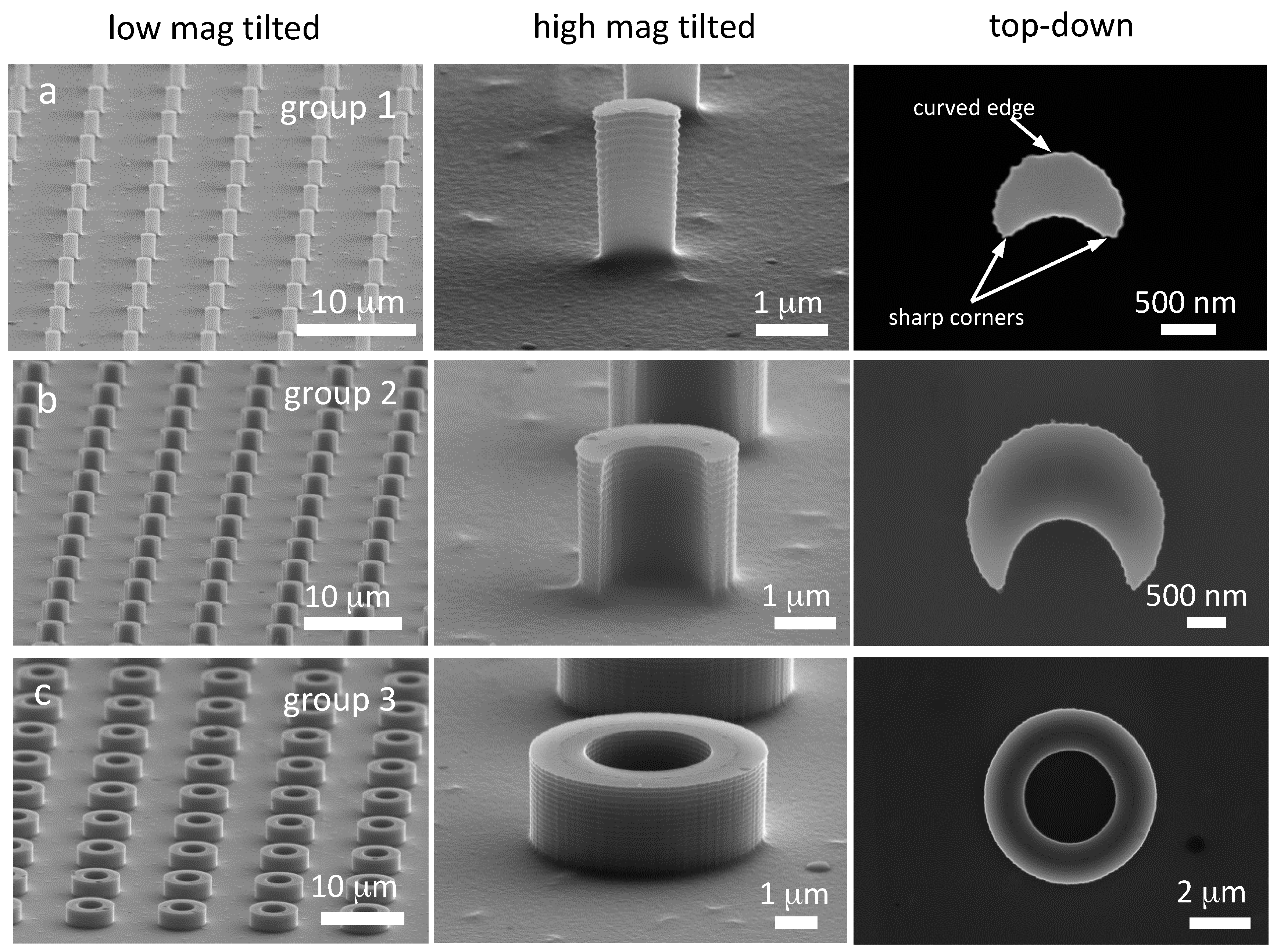
3.1. Silicon Pillars
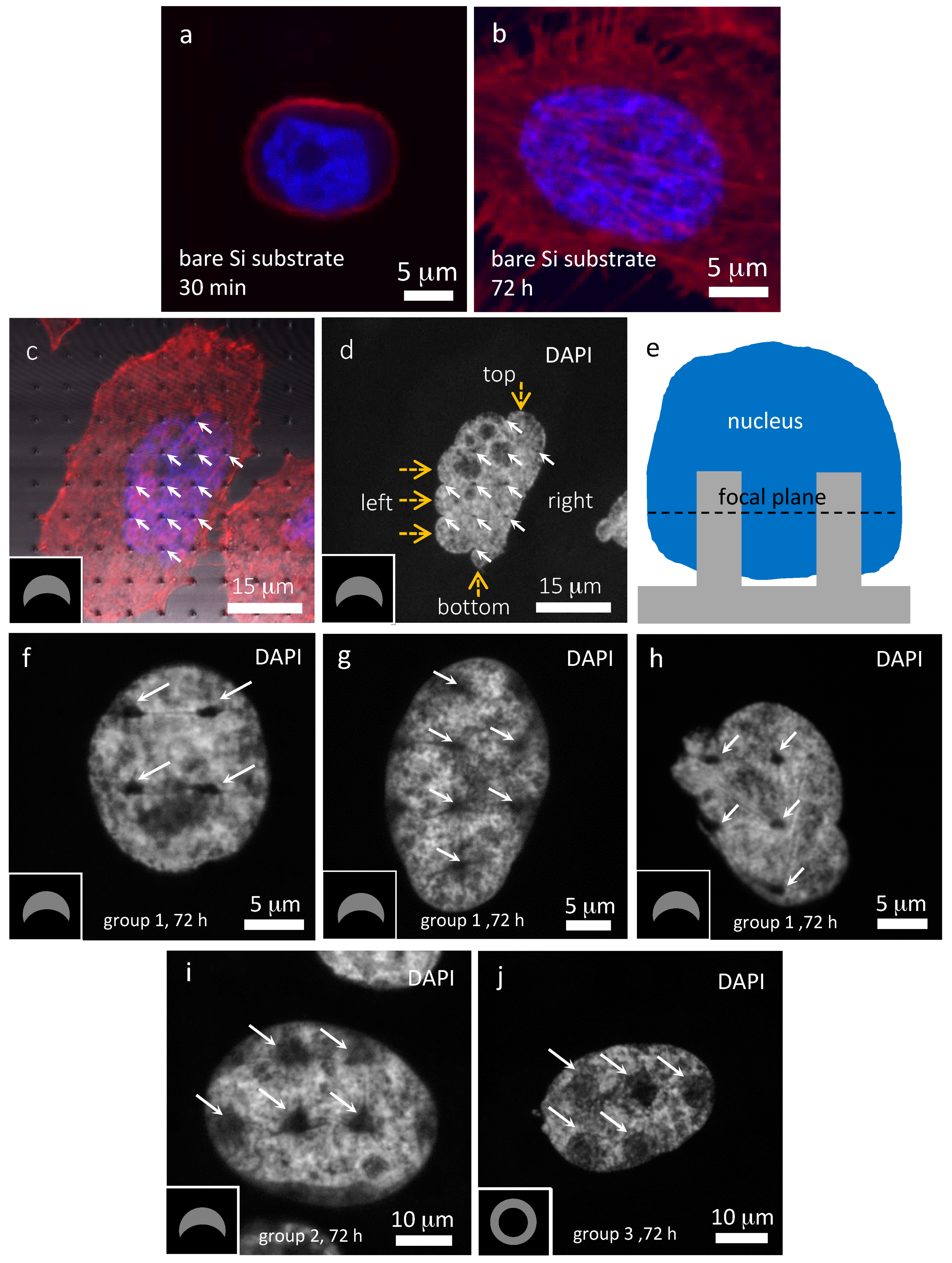
3.2. Cells on Bare Silicon Substrates
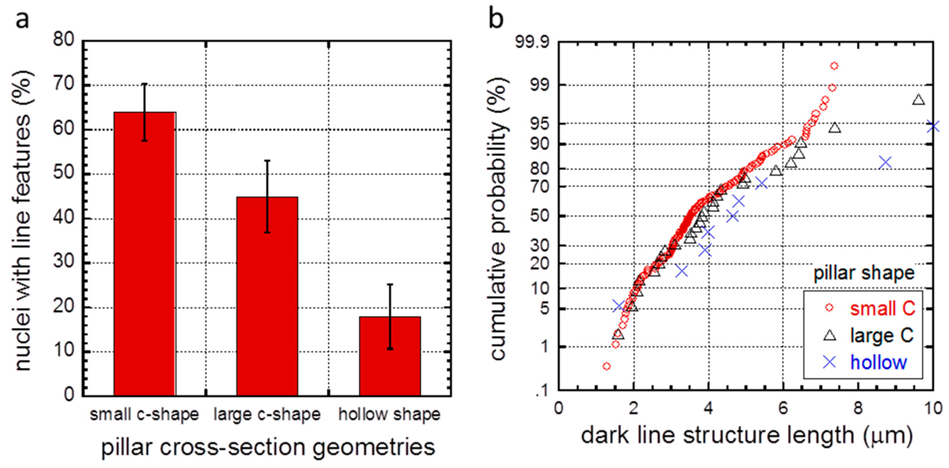
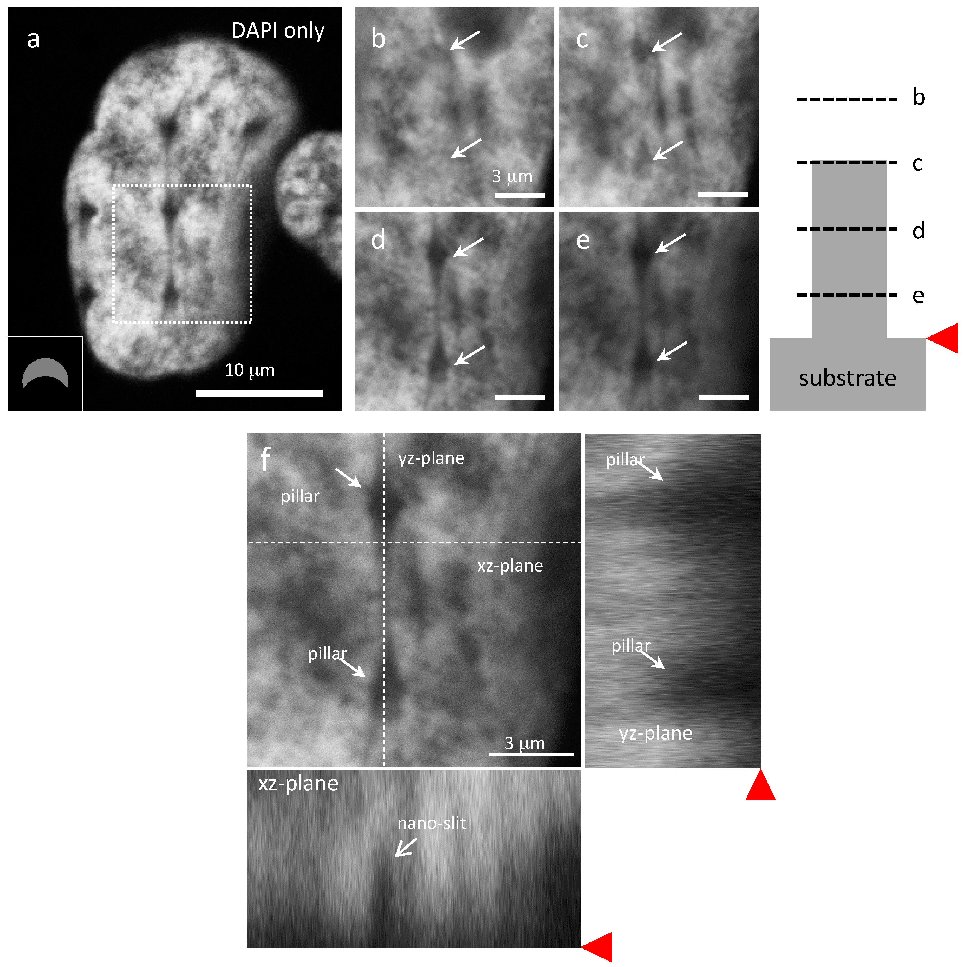
3.3. Cells on Patterned Silicon Substrates
4. Conclusions
Supplementary Materials
Acknowledgments
Author Contributions
Conflicts of Interest
References
- Bettinger, C.J.; Langer, R.; Borenstein, J.T. Engineering Substrate Micro- and Nanotopography to Control Cell Function. Angew. Chem. Int. Ed. Engl. 2009, 48, 5406–5415. [Google Scholar] [CrossRef] [PubMed]
- Bettinger, C.J.; Orrick, B.; Misra, A.; Langer, R.; Borenstein, J.T. Microfabrication of poly (glycerol-sebacate) for contact guidance applications. Biomaterials 2006, 27, 2558–2565. [Google Scholar] [CrossRef] [PubMed]
- Bucaro, M.A.; Vasquez, Y.; Hatton, B.D.; Aizenberg, J. Fine-tuning the degree of stem cell polarization and alignment on ordered arrays of high-aspect-ratio nanopillars. ACS Nano 2012, 6, 6222–6230. [Google Scholar] [CrossRef] [PubMed]
- Hanson, L.; Zhao, W.; Lou, H.-Y.; Lin, Z.C.; Lee, S.W.; Chowdary, P.; Cui, Y.; Cui, B. Vertical nanopillars for in situ probing of nuclear mechanics in adherent cells. Nat. Nanotechnol. 2015, 10, 554–562. [Google Scholar]
- Hu, W.; Crouch, A.S.; Miller, D.; Aryal, M.; Luebke, K.J. Inhibited cell spreading on polystyrene nanopillars fabricated by nanoimprinting and in situ elongation. Nanotechnology 2010, 21, 385301. [Google Scholar] [CrossRef] [PubMed]
- Kim, D.-H.; Provenzano, P.P.; Smith, C.L.; Levchenko, A. Matrix nanotopography as a regulator of cell function. J. Cell Biol. 2012, 197, 351–360. [Google Scholar] [CrossRef] [PubMed]
- Liu, X.; Chen, L.; Liu, H.; Yang, G.; Zhang, P.; Han, D.; Wang, S.; Jiang, L. Bio-inspired soft polystyrene nanotube substrate for rapid and highly efficient breast cancer-cell capture. NPG Asia Mater. 2013, 5, e63. [Google Scholar] [CrossRef]
- Wang, S.; Wan, Y.; Liu, Y. Effects of nanopillar array diameter and spacing on cancer cell capture and cell behaviors. Nanoscale 2014, 6, 12482–12489. [Google Scholar] [CrossRef] [PubMed]
- Wang, L.; Asghar, W.; Demirci, U.; Wan, Y. Nanostructured substrates for isolation of circulating tumor cells. Nano Today 2013, 8, 347–387. [Google Scholar] [CrossRef] [PubMed]
- Kim, W.; Ng, J.K.; Kunitake, M.E.; Conklin, B.R.; Yang, P. Interfacing silicon nanowires with mammalian cells. J. Am. Chem. Soc. 2007, 129, 7228–7229. [Google Scholar] [CrossRef] [PubMed]
- Fujie, T.; Shi, X.; Ostrovidov, S.; Liang, X.; Nakajima, K.; Chen, Y.; Wu, H.; Khademhosseini, A. Biomaterials Spatial coordination of cell orientation directed by nanoribbon sheets. Biomaterials 2015, 53, 86–94. [Google Scholar] [CrossRef] [PubMed]
- Lu, Y.; Peng, S.; Luo, D.; Lal, A. Low-concentration mechanical biosensor based on a photonic crystal nanowire array. Nat. Commun. 2011, 2, 576–578. [Google Scholar] [CrossRef] [PubMed]
- Gupta, B.; Zhu, Y.; Guan, B.; Reece, P.J.; Gooding, J.J. Functionalised porous silicon as a biosensor: Emphasis on monitoring cells in vivo and in vitro. Analyst 2013, 138, 3593–3615. [Google Scholar] [CrossRef] [PubMed]
- Xie, C.; Lin, Z.; Hanson, L.; Cui, Y.; Cui, B. Intracellular recording of action potentials by nanopillar electroporation. Nat. Nanotechnol. 2012, 7, 185–190. [Google Scholar] [CrossRef] [PubMed]
- Xie, C.; Hanson, L.; Xie, W.; Lin, Z.; Cui, B.; Cui, Y. Noninvasive neuron pinning with nanopillar arrays. Nano Lett. 2010, 10, 4020–4024. [Google Scholar] [CrossRef] [PubMed]
- Spira, M.E.; Hai, A. Multi-electrode array technologies for neuroscience and cardiology. Nat. Nanotechnol. 2013, 8, 83–94. [Google Scholar] [CrossRef] [PubMed]
- Nguyen, J.K.; Park, D.J.; Skousen, J.L.; Jorfi, M.; Skousen, J.L.; Weder, C.; Potter, K.A.; Buck, A.C.; Self, W.K.; Mcconnell, G.C.; et al. Mechanically adaptive intracortical implants improve the proximity of neuronal cell bodies. J. Neural Eng. 2011, 8, 066011. [Google Scholar]
- Potter, K.A.; Buck, A.C.; Self, W.K.; Mcconnell, G.C.; Rees, H.D.; Levey, A.I.; Nguyen, J.K.; Park, D.J.; Skousen, J.L.; Prasad, A.; et al. Comprehensive characterization and failure modes of tungsten microwire. J. Neural Eng. 2012, 9, 56015. [Google Scholar]
- Harris, J.P.; Hess, A.E.; Rowan, S.J.; Weder, C.; Zorman, C.A.; Tyler, D.J.; Capadona, J.R. In vivo deployment of mechanically adaptive nanocomposites for intracortical microelectrodes. J. Neural Eng. 2011, 8, 046010. [Google Scholar] [CrossRef] [PubMed]
- Okun, M.; Lak, A.; Carandini, M.; Harris, K.D. Long term recordings with immobile silicon probes in the mouse cortex. PLoS ONE 2016, 11, 1–17. [Google Scholar] [CrossRef] [PubMed]
- Polikov, V.S.; Tresco, P.A.; Reichert, W.M. Response of brain tissue to chronically implanted neural electrodes. J. Neurosci. Methods 2005, 148, 1–18. [Google Scholar] [CrossRef] [PubMed]
- Pan, Z.; Yan, C.; Peng, R.; Zhao, Y.; He, Y.; Ding, J. Control of cell nucleus shapes via micropillar patterns. Biomaterials 2012, 33, 1730–1735. [Google Scholar] [CrossRef] [PubMed]
- Davidson, P.M.; Özçelik, H.; Hasirci, V.; Reiter, G.; Anselme, K. Microstructured surfaces cause severe but non-detrimental deformation of the cell nucleus. Adv. Mater. 2009, 21, 3586–3590. [Google Scholar] [CrossRef]
- Badique, F.; Stamov, D.R.; Davidson, P.M.; Veuillet, M.; Reiter, G.; Freund, J.; Franz, C.M.; Anselme, K. Biomaterials Directing nuclear deformation on micropillared surfaces by substrate geometry and cytoskeleton organization. Biomaterials 2013, 34, 2991–3001. [Google Scholar] [CrossRef] [PubMed]
- Tan, J.L.; Tien, J.; Pirone, D.M.; Gray, D.S.; Bhadriraju, K.; Chen, C.S. Cells lying on a bed of microneedles: An approach to isolate mechanical force. Proc. Natl. Acad. Sci. USA 2003, 100, 1484–1489. [Google Scholar] [CrossRef] [PubMed]
- Shakoor, A.; Muhammad, R.; Thomas, N.L.; Silberschmidt, V.V. Mechanical and thermal characterisation of poly (l-lactide) composites reinforced with hemp fibres. J. Phys. Conf. Ser. 2013, 451, 12010. [Google Scholar] [CrossRef]
- Petersen, K.E. Silicon as a Mehcanical Material. Proc. IEEE 1982, 70, 420–455. [Google Scholar] [CrossRef]
- Johnson, K.L. Contact Mechanics; Cambridge University Press: Cambridge, UK, 1985. [Google Scholar]
- Jahed, Z.; Shahsavan, H.; Verma, M.S.; Rogowski, J.L.; Seo, B.B.; Zhao, B.; Tsui, T.Y.; Gu, F.X.; Mofrad, M.R.K. Bacterial networks on hydrophobic micropillars. ACS Nano 2017, 11, 675–683. [Google Scholar] [CrossRef] [PubMed]
- Jahed, Z.; Lin, P.; Seo, B.B.; Verma, M.S.; Gu, F.X.; Tsui, T.Y.; Mofrad, M.R.K. Responses of Staphylococcus aureus bacterial cells to nanocrystalline nickel nanostructures. Biomaterials 2014, 35, 4249–4254. [Google Scholar] [CrossRef] [PubMed]
- World Health Organization; International Agency for Research on Cancer. World Cancer Report 2014; IARC Press: Lyon, France, 2014. [Google Scholar]
- Laermer, F.; Schilp, A. Method of Anisotropically Etching Silicon. U.S. Patent 5,501,893, 26 March 1996. [Google Scholar]
- Özçelik, H.; Padeste, C.; Hasirci, V. Systematically organized nanopillar arrays reveal differences in adhesion and alignment properties of BMSC and Saos-2 cells. Coll. Surf. B Biointerfaces 2014, 119, 71–81. [Google Scholar]
- Li, P.; Wang, D.; Li, H.; Yu, Z.; Chen, X.; Fang, J. Identification of nucleolus-localized PTEN and its function in regulating ribosome biogenesis. Mol. Biol. Rep. 2014, 41, 6383–6390. [Google Scholar] [CrossRef] [PubMed]
- Park, S.; Ang, R.R.; Duffy, S.P.; Bazov, J.; Chi, K.N.; Black, P.C.; Ma, H. Morphological differences between circulating tumor cells from prostate cancer patients and cultured prostate cancer cells. PLoS ONE 2014, 9, e85264. [Google Scholar] [CrossRef] [PubMed]
- Nexcelom Bioscience LLC, NCI-60 Cancer Cell Lines. 2017. [Online]. Available online: http://www.nexcelom.com/Applications/bright-field-analysis-of-nci-60-cancer-cell-lines.php (accessed on 16 June 2017).
- Albuschies, J.; Vogel, V. The role of filopodia in the recognition of nanotopographies. Sci. Rep. 2013, 3. [Google Scholar] [CrossRef] [PubMed]
- Jahed, Z.; Molladavoodi, S.; Seo, B.B.; Gorbet, M.; Tsui, T.Y.; Mofrad, M.R.K. Cell responses to metallic nanostructure arrays with complex geometries. Biomaterials 2014, 35, 9363–9371. [Google Scholar] [CrossRef] [PubMed]
- Aalipour, A.; Xu, A.M.; Leal-ortiz, S.; Garner, C.C.; Melosh, N.A. Plasma membrane and actin cytoskeleton as synergistic barriers to nanowire cell penetration. Langmuir 2014, 30, 12362–12367. [Google Scholar] [CrossRef] [PubMed]
- Robinson, J.T.; Jorgolli, M.; Shalek, A.K.; Yoon, M.; Gertner, R.S.; Park, H. Vertical nanowire electrode arrays as a scalable platform for intracellular interfacing to neuronal circuits. Nat. Nanotechnol. 2012, 7, 180–184. [Google Scholar] [CrossRef] [PubMed]
- Xie, X.; Aalipour, A.; Gupta, S.V.; Melosh, N.A.; Science, M.; States, U.; Sciences, T.; Francisco, S.; Francisco, S.; States, U. Determining the time window for dynamic nanowire cell penetration. ACS Nano 2015, 8, 11667–11677. [Google Scholar] [CrossRef] [PubMed]
- Berthing, T.; Bonde, S.; Rostgaard, K.R.; Madsen, M.H.; Sørensen, C.B.; Nygård, J.; Martinez, K.L. Cell membrane conformation at vertical nanowire array interface revealed by fluorescence imaging. Nanotechnology 2012, 23, 415102. [Google Scholar] [CrossRef] [PubMed]


| Group | Pillar Shape | Outer Diameter (μm) | Wall Thickness (μm) | Center-to-Center Distance (μm) | Nuclei Inspected | Nuclei with Line Features | % Nuclei with Line Features |
|---|---|---|---|---|---|---|---|
| 1 | small C-shape | 1.2 | -- | 6.2 | 55 | 35 | 64 ± 6 |
| 2 | large C-shape | 2.7 | -- | 7.6 | 38 | 17 | 45 ± 8 |
| 3 | hollow | 5.6 | 1.3 | 10.5 | 28 | 5 | 18 ± 7 |
© 2017 by the authors. Licensee MDPI, Basel, Switzerland. This article is an open access article distributed under the terms and conditions of the Creative Commons Attribution (CC BY) license (http://creativecommons.org/licenses/by/4.0/).
Share and Cite
Seo, B.B.; Jahed, Z.; Coggan, J.A.; Chau, Y.Y.; Rogowski, J.L.; Gu, F.X.; Wen, W.; Mofrad, M.R.K.; Tsui, T.Y. Mechanical Contact Characteristics of PC3 Human Prostate Cancer Cells on Complex-Shaped Silicon Micropillars. Materials 2017, 10, 892. https://doi.org/10.3390/ma10080892
Seo BB, Jahed Z, Coggan JA, Chau YY, Rogowski JL, Gu FX, Wen W, Mofrad MRK, Tsui TY. Mechanical Contact Characteristics of PC3 Human Prostate Cancer Cells on Complex-Shaped Silicon Micropillars. Materials. 2017; 10(8):892. https://doi.org/10.3390/ma10080892
Chicago/Turabian StyleSeo, Brandon B., Zeinab Jahed, Jennifer A. Coggan, Yeung Yeung Chau, Jacob L. Rogowski, Frank X. Gu, Weijia Wen, Mohammad R. K. Mofrad, and Ting Yiu Tsui. 2017. "Mechanical Contact Characteristics of PC3 Human Prostate Cancer Cells on Complex-Shaped Silicon Micropillars" Materials 10, no. 8: 892. https://doi.org/10.3390/ma10080892
APA StyleSeo, B. B., Jahed, Z., Coggan, J. A., Chau, Y. Y., Rogowski, J. L., Gu, F. X., Wen, W., Mofrad, M. R. K., & Tsui, T. Y. (2017). Mechanical Contact Characteristics of PC3 Human Prostate Cancer Cells on Complex-Shaped Silicon Micropillars. Materials, 10(8), 892. https://doi.org/10.3390/ma10080892