An Advanced Characterization Method for the Elastic Modulus of Nanoscale Thin-Films Using a High-Frequency Micromechanical Resonator


Abstract
:1. Introduction
2. Materials and Methods
2.1. Materials
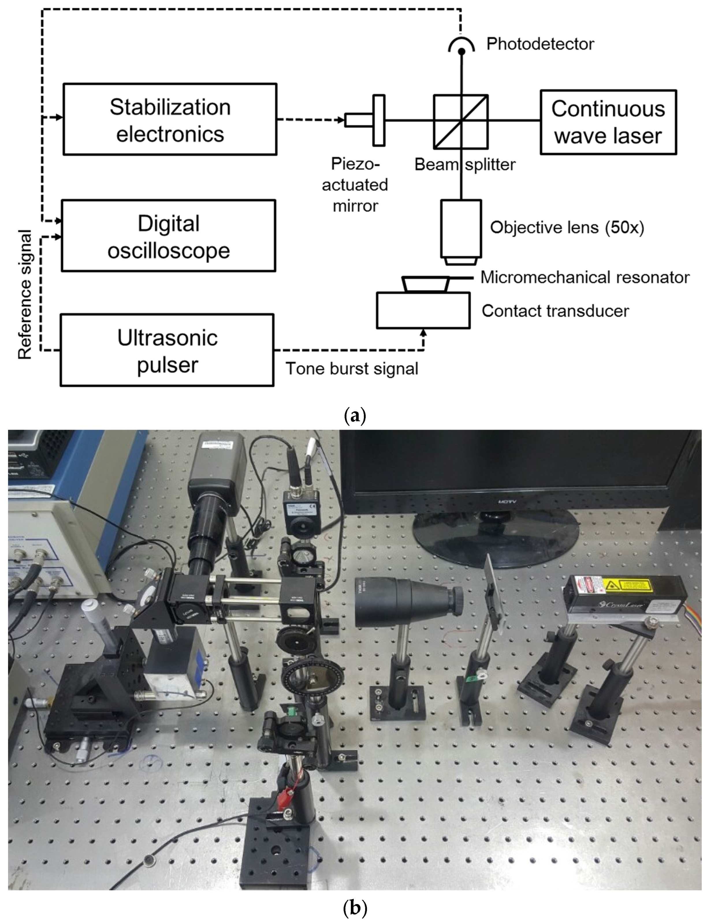
2.2. Characterization Methods
3. Theory and Calculation
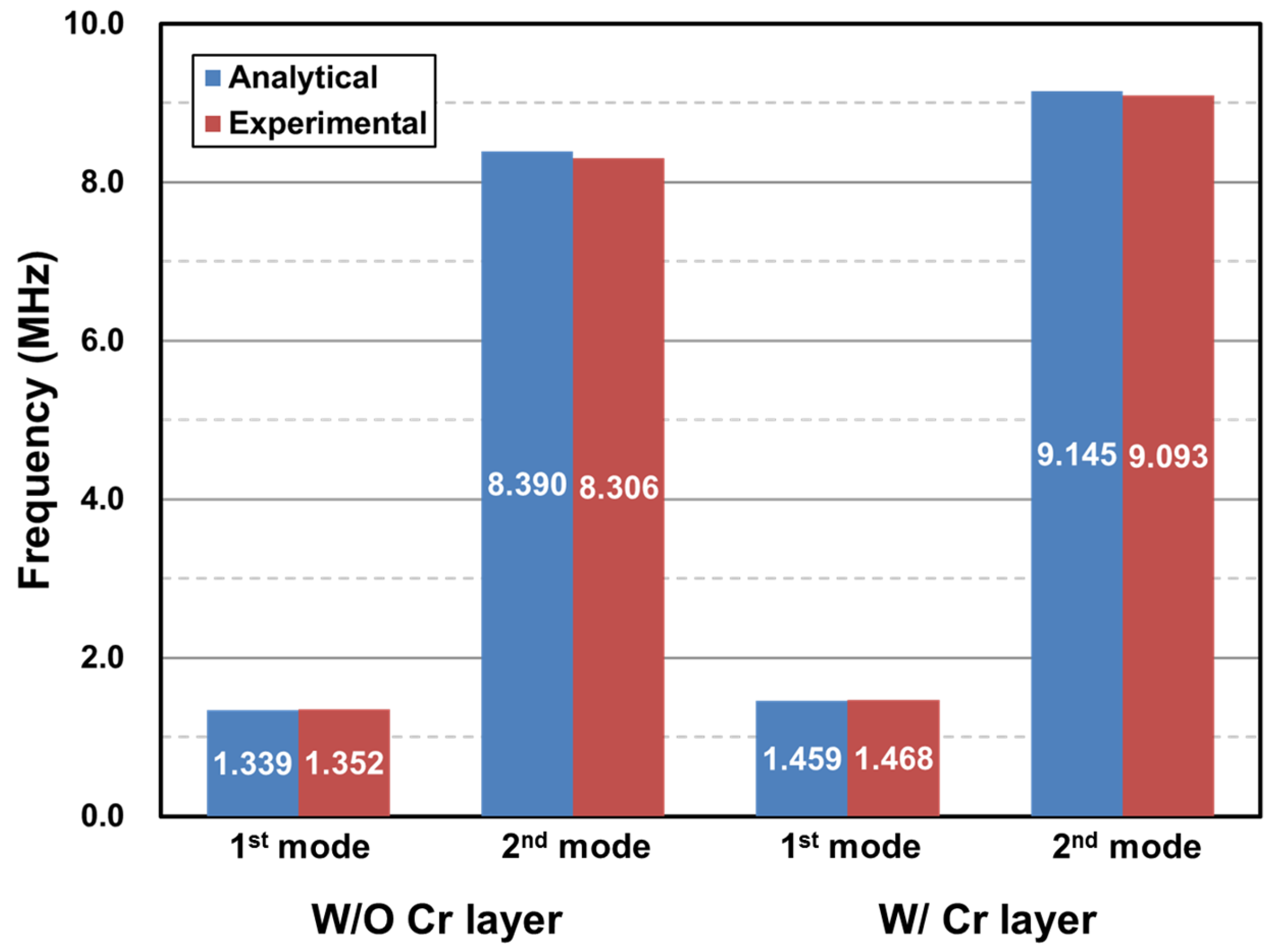
4. Results and Discussion
5. Conclusions
Acknowledgments
Conflicts of Interest
References
- Chang, K.-B.; Kim, Y.Y.; Sue, J.; Lee, H.; Chung, W.-Y.; Lee, K.-H.; Park, Y.-K.; Jung, E.; Chung, I. The novel stress simulation method for contemporary dram capacitor arrays. In Proceedings of the 2013 International Conference on Simulation of Semiconductor Processes and Devices (SISPAD), Glasgow, UK, 3–5 September 2013; IEEE: New York, NY, USA, 2013; pp. 424–427. [Google Scholar]
- Bamber, M.; Cooke, K.; Mann, A.; Derby, B. Accurate determination of Young’s modulus and Poisson’s ratio of thin films by a combination of acoustic microscopy and nanoindentation. Thin Solid Films 2001, 398, 299–305. [Google Scholar] [CrossRef]
- Pharr, G.M. Recent advances in small-scale mechanical property measurement by nanoindentation. Curr. Opin. Solid State Mater. Sci. 2015, 19, 315–316. [Google Scholar] [CrossRef]
- Kihara, Y.; Nagoshi, T.; Chang, T.-F.M.; Hosoda, H.; Tatsuo, S.; Sone, M. Tensile behavior of micro-sized specimen made of single crystalline nickel. Mater. Lett. 2015, 153, 36–39. [Google Scholar] [CrossRef]
- Zhang, F.; Krishnaswamy, S.; Fei, D.; Rebinsky, D.A.; Feng, B. Ultrasonic characterization of mechanical properties of Cr-and W-doped diamond-like carbon hard coatings. Thin Solid Films 2006, 503, 250–258. [Google Scholar] [CrossRef]
- Mahmoud, M.A. Validity and accuracy of resonance shift prediction formulas for microcantilevers: A review and comparative study. Crit. Rev. Solid State Mater. Sci. 2016, 41, 386–429. [Google Scholar] [CrossRef]
- Lakshmoji, K.; Prabakar, K.; Kumar, A.; Brijitta, J.; Jayapandian, J.; Tata, B.V.R.; Tyagi, A.K.; Sundar, C.S. Microcantilever-based mass sensors: Working at higher modes against reducing the dimensions. Micro Nano Lett. 2012, 7, 613–616. [Google Scholar] [CrossRef]
- Narducci, M.; Figueras, E.; Lopez, M.J.; Gracia, I.; Santander, J.; Ivanov, P.; Fonseca, L.; Cane, C. Sensitivity improvement of a microcantilever based mass sensor. Microelectron. Eng. 2009, 86, 1187–1189. [Google Scholar] [CrossRef]
- Brown, K.A.; Yang, B.H.; Westervelt, R.M. Self-driving capacitive cantilevers for high-frequency atomic force microscopy. Appl. Phys. Lett. 2012, 100, 053110. [Google Scholar] [CrossRef]
- Chaste, J.; Eichler, A.; Moser, J.; Ceballos, G.; Rurali, R.; Bachtold, A. A nanomechanical mass sensor with yoctogram resolution. Nat. Nanotechnol. 2012, 7, 300–303. [Google Scholar] [CrossRef] [PubMed]
- Li, M.; Tang, H.X.; Roukes, M.L. Ultra-sensitive NEMS-based cantilevers for sensing, scanned probe and very high-frequency applications. Nat. Nanotechnol. 2007, 2, 114–120. [Google Scholar] [CrossRef] [PubMed]
- Burke, B.G.; LaVan, D.A. Characterization of a 10-MHz quadrant APD for measuring frequency oscillations and tip displacements of microcantilevers. Appl. Phys. B Lasers Opt. 2012, 109, 127–132. [Google Scholar] [CrossRef]
- Landau, L.D.; Kosevich, A.; Pitaevskii, L.P.; Lifshitz, E.M. Theory of Elasticity; Pergamon Press: Oxford, UK, 1986. [Google Scholar]
- Cortes, F.; Sarria, I. Dynamic analysis of three-layer sandwich beams with thick viscoelastic damping core for finite element applications. Shock Vib. 2015, 2015. [Google Scholar] [CrossRef]
- Birleanu, C.; Pustan, M. The Effect of Film Thickness on the Tribomechanical Properties of the Chrome-Gold Thin Film. In Proceedings of the 2016 Symposium on Design, Test, Integration and Packaging of MEMS/MOEMS (DTIP), Budapest, Hungary, 30 May–2 June 2016; IEEE: New York, NY, USA, 2016; pp. 1–6. [Google Scholar]
- Salvadori, M.C.; Brown, I.G.; Vaz, A.R.; Melo, L.L.; Cattani, M. Measurement of the elastic modulus of nanostructured gold and platinum thin films. Phys. Rev. B 2003, 67. [Google Scholar] [CrossRef]
- Nix, W.D. Mechanical properties of thin films. Metall. Mater. Trans. A 1989, 20, 2217–2245. [Google Scholar] [CrossRef]
- Pamula, V.K.; Jog, A.; Fair, R.B. Mechanical Property Measurement of Thin-Film Gold Using Thermally Actuated Bimetallic Cantilever Beams. In Proceedings of the Modeling and Simulation of Microsystems, Hilton Head Island, SC, USA, 19–21 March 2001. [Google Scholar]
- Huh, Y.-H.; Kim, D.-I.; Kim, D.-J.; Lee, H.-M.; Park, J.-H. Dependency of micro-mechanical properties of gold thin films on grain size. In Engineering Against Fracture; Springer: Berlin, German, 2009; pp. 339–346. [Google Scholar]
- Espinosa, H.D.; Prorok, B.C. Size effects on the mechanical behavior of gold thin films. J. Mater. Sci. 2003, 38, 4125–4128. [Google Scholar] [CrossRef]
- Nilsson, S.G.; Borrise, X.; Montelius, L. Size effect on Young’s modulus of thin chromium cantilevers. Appl. Phys. Lett. 2004, 85, 3555–3557. [Google Scholar] [CrossRef]
- Rehder, G.P.; Carreño, M.N. Piezoelectric stimulation of microcantilever beams for Young’s modulus determination of Amorphous Hydrogenated Silicon Carbide. ECS Trans. 2008, 14, 63–71. [Google Scholar]
- Schneider, D.; Tucker, M.D. Non-destructive characterization and evaluation of thin films by laser-induced ultrasonic surface waves. Thin Solid Films 1996, 290, 305–311. [Google Scholar] [CrossRef]
- Waggoner, P.S.; Craighead, H.G. Micro-and nanomechanical sensors for environmental, chemical, and biological detection. Lab Chip 2007, 7, 1238–1255. [Google Scholar] [CrossRef] [PubMed]
- Ghatkesar, M.K.; Barwich, V.; Braun, T.; Ramseyer, J.-P.; Gerber, C.; Hegner, M.; Lang, H.P.; Drechsler, U.; Despont, M. Higher modes of vibration increase mass sensitivity in nanomechanical microcantilevers. Nanotechnology 2007, 18, 445502. [Google Scholar] [CrossRef]
- Chaudhary, M.; Gupta, A. Microcantilever-based Sensors. Def. Sci. J. 2009, 59, 634–641. [Google Scholar] [CrossRef]


| Property | Material | ||
|---|---|---|---|
| Gold | Quartz | Chromium | |
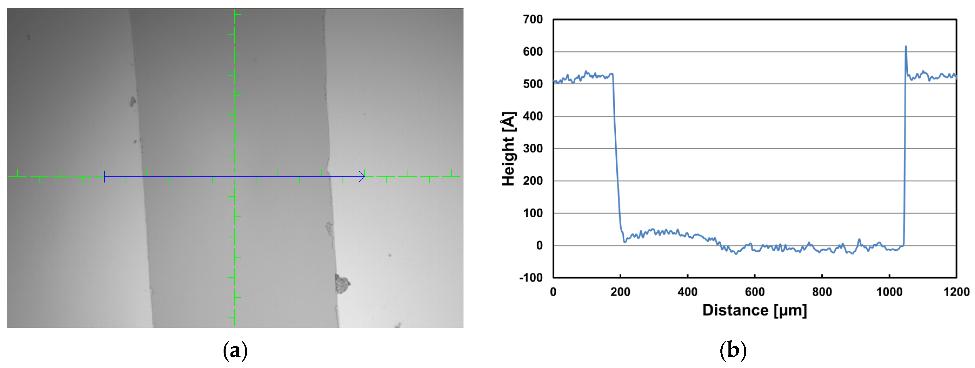
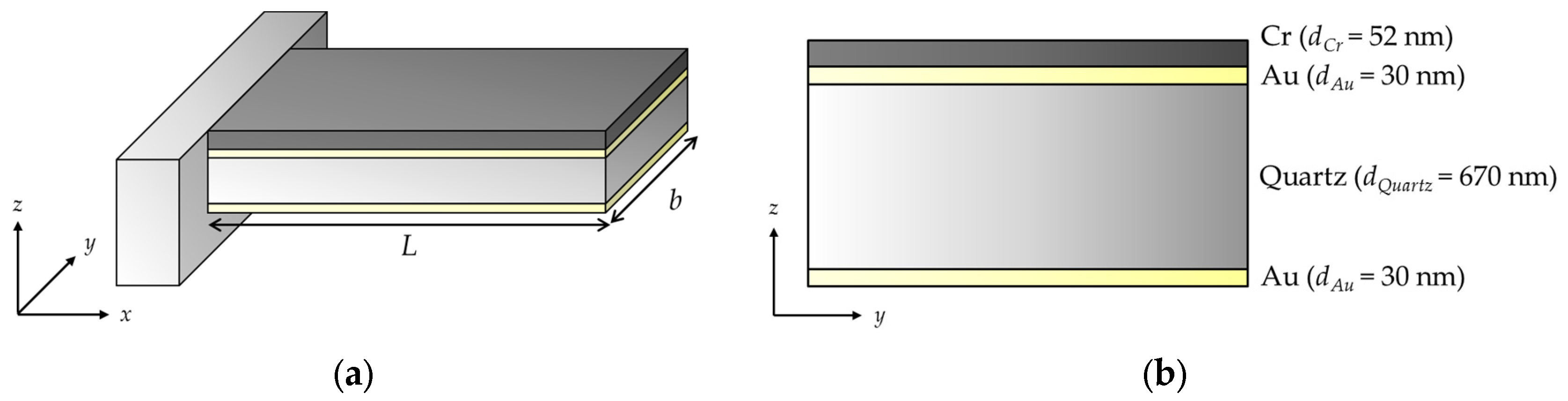
| Thickness (d) (nm) | 30 | 670 | 52 |
| Density (ρ) (kg/m3) | 19,300 | 2200 | 7190 |
| Young’s modulus (E) (GPa) | 79 | 73 | - |
| Reference | Fabrication Method | Characterization Method | Film Thickness (nm) | Young’s Modulus (GPa) |
|---|---|---|---|---|
| [15] | E-beam evaporation | Nanoindentation testing | 100 | 55.5 |
| 300 | 64.1 | |||
| 500 | 88.76 | |||
| [16] | Metal plasma immersion ion implantation and deposition | Microcantilever beam testing | 19–62 | 69.1 |
| [17] | E-beam evaporation | Microbeam testing | 1000 | 57 |
| Nanoindentation testing | 74 | |||
| [18] | Multi-user microelectromechanical systems processes | Microcantilever beam testing | 500 | 78 |
| [19] | Sputtering | Microtensile testing | 180 | 61.0 |
| 310 | 49.5 | |||
| 500 | 53.9 | |||
| 680 | 53.1 | |||
| 950 | 51.2 | |||
| 1000 | 57.5 | |||
| [20] | E-beam evaporation | Membrane deflection experiment | 300 | 53–55 |
| 500 | ||||
| 1000 |
© 2017 by the author. Licensee MDPI, Basel, Switzerland. This article is an open access article distributed under the terms and conditions of the Creative Commons Attribution (CC BY) license (http://creativecommons.org/licenses/by/4.0/).
Share and Cite
Kim, Y.Y. An Advanced Characterization Method for the Elastic Modulus of Nanoscale Thin-Films Using a High-Frequency Micromechanical Resonator. Materials 2017, 10, 806. https://doi.org/10.3390/ma10070806
Kim YY. An Advanced Characterization Method for the Elastic Modulus of Nanoscale Thin-Films Using a High-Frequency Micromechanical Resonator. Materials. 2017; 10(7):806. https://doi.org/10.3390/ma10070806
Chicago/Turabian StyleKim, Yun Young. 2017. "An Advanced Characterization Method for the Elastic Modulus of Nanoscale Thin-Films Using a High-Frequency Micromechanical Resonator" Materials 10, no. 7: 806. https://doi.org/10.3390/ma10070806
APA StyleKim, Y. Y. (2017). An Advanced Characterization Method for the Elastic Modulus of Nanoscale Thin-Films Using a High-Frequency Micromechanical Resonator. Materials, 10(7), 806. https://doi.org/10.3390/ma10070806