
3D Molding of Veneers by Mechanical and Pneumatic Methods

Abstract
:
1. Introduction
2. Experimental Section
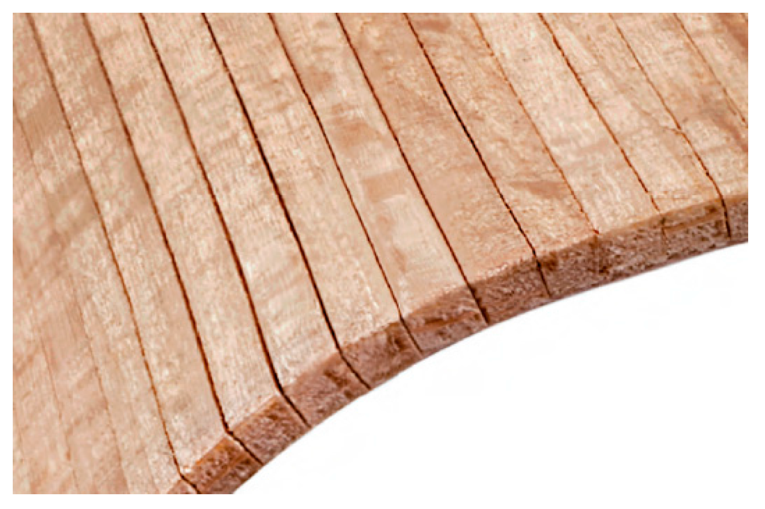
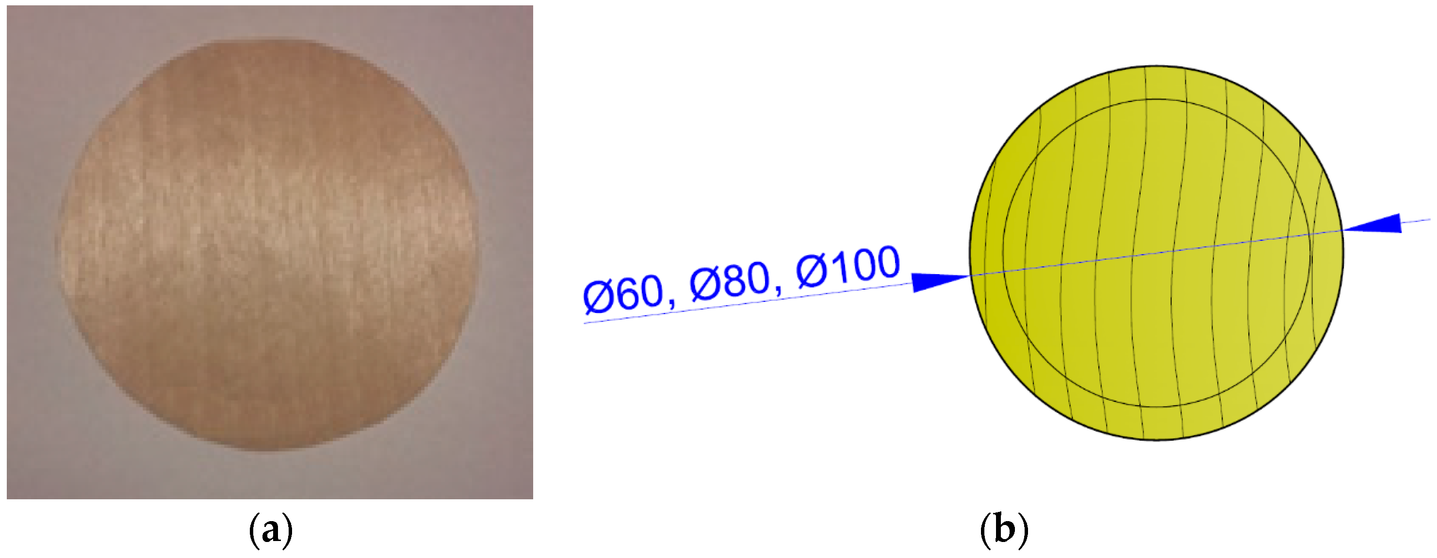
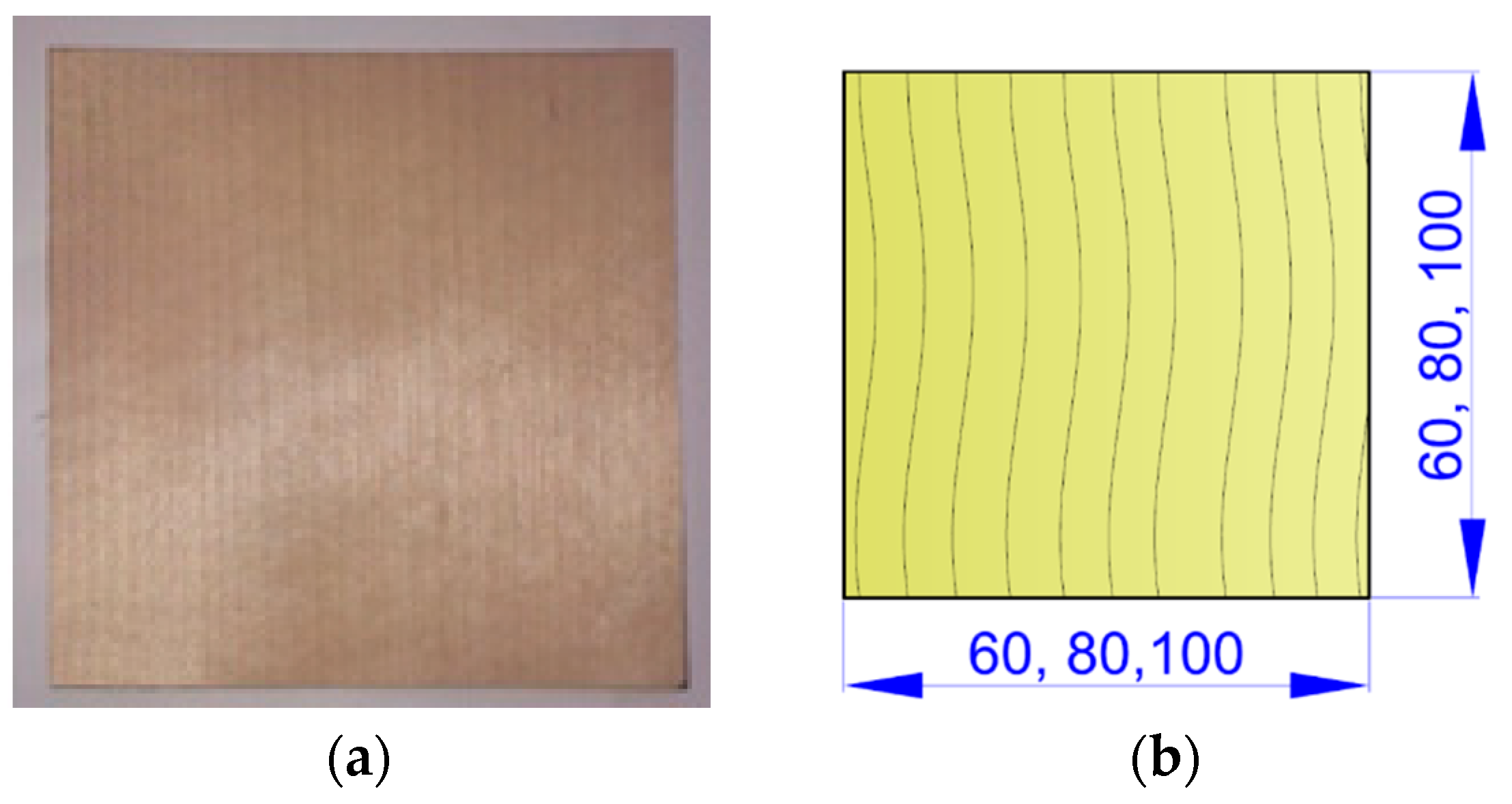
2.1. Material
2.2. Methods
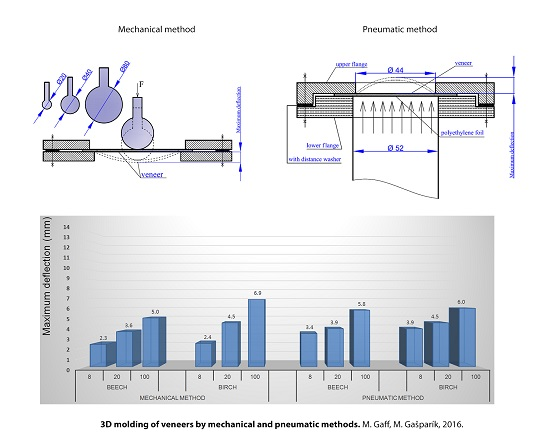
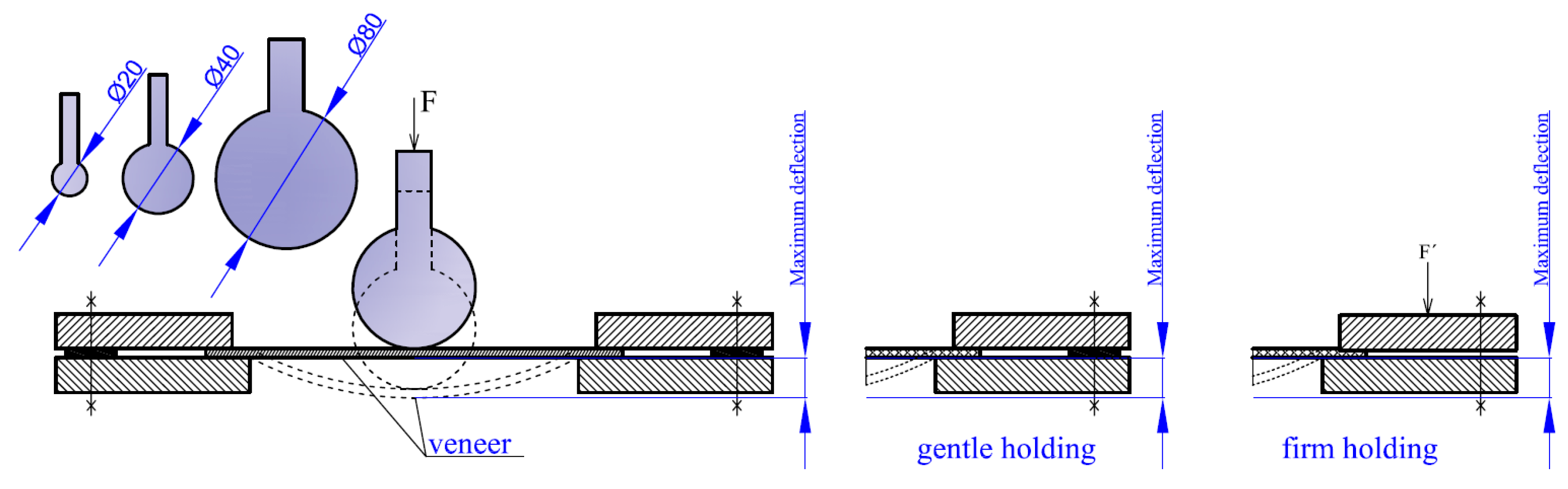
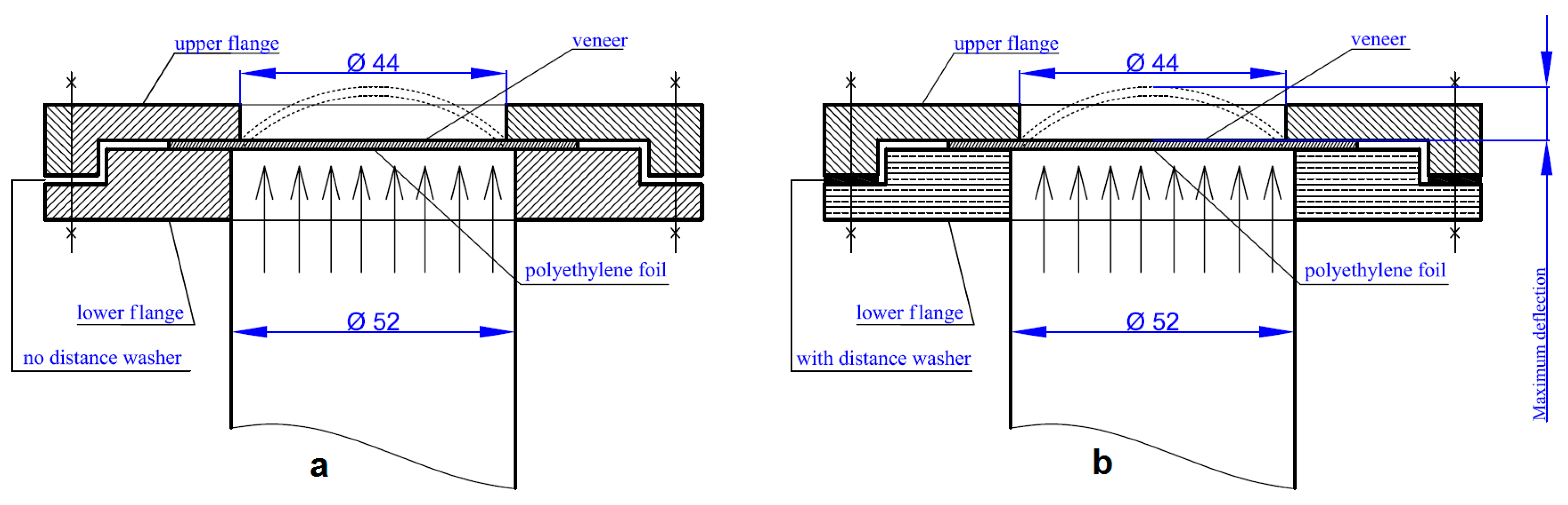
2.2.1. General Basic Mechanical Method
2.2.2. Mechanical Method with Lamination Treatment and Steaming
2.2.3. Mechanical Method with Plasticizing by Water and Ammonia
2.2.4. Pneumatic Method
2.2.5. Measurements
3. Results and Discussion
3.1. Maximum Deflection
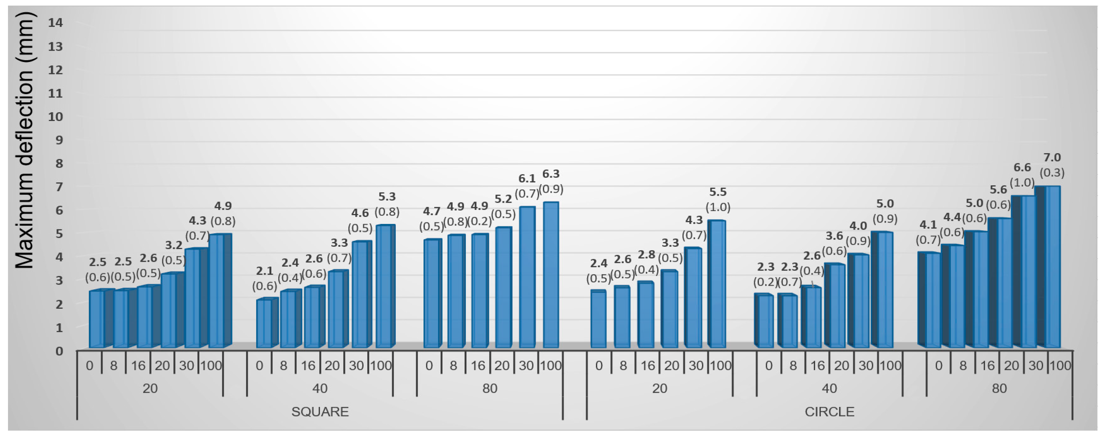
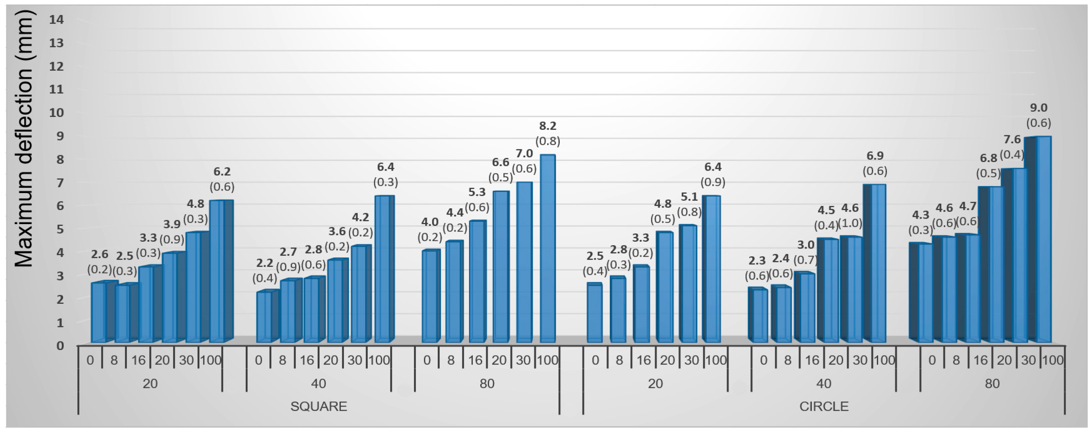
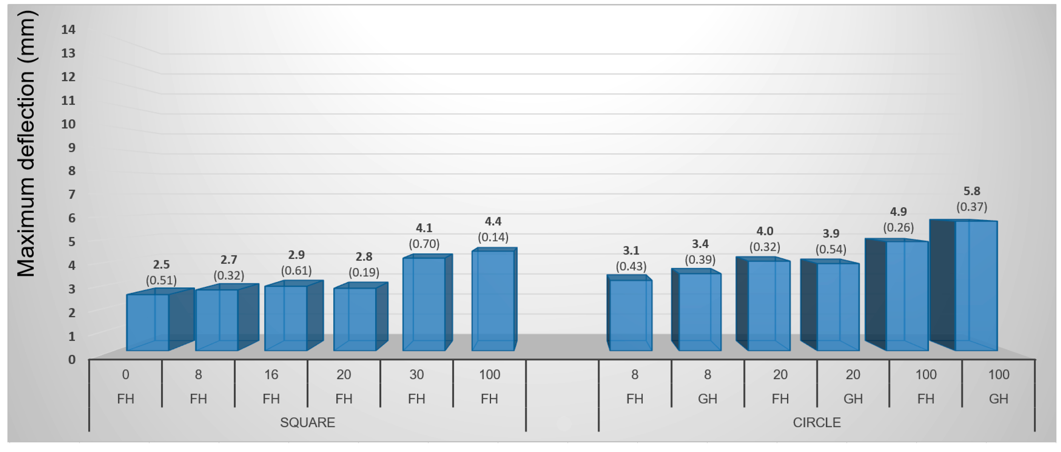
3.1.1. General Basic Mechanical Method
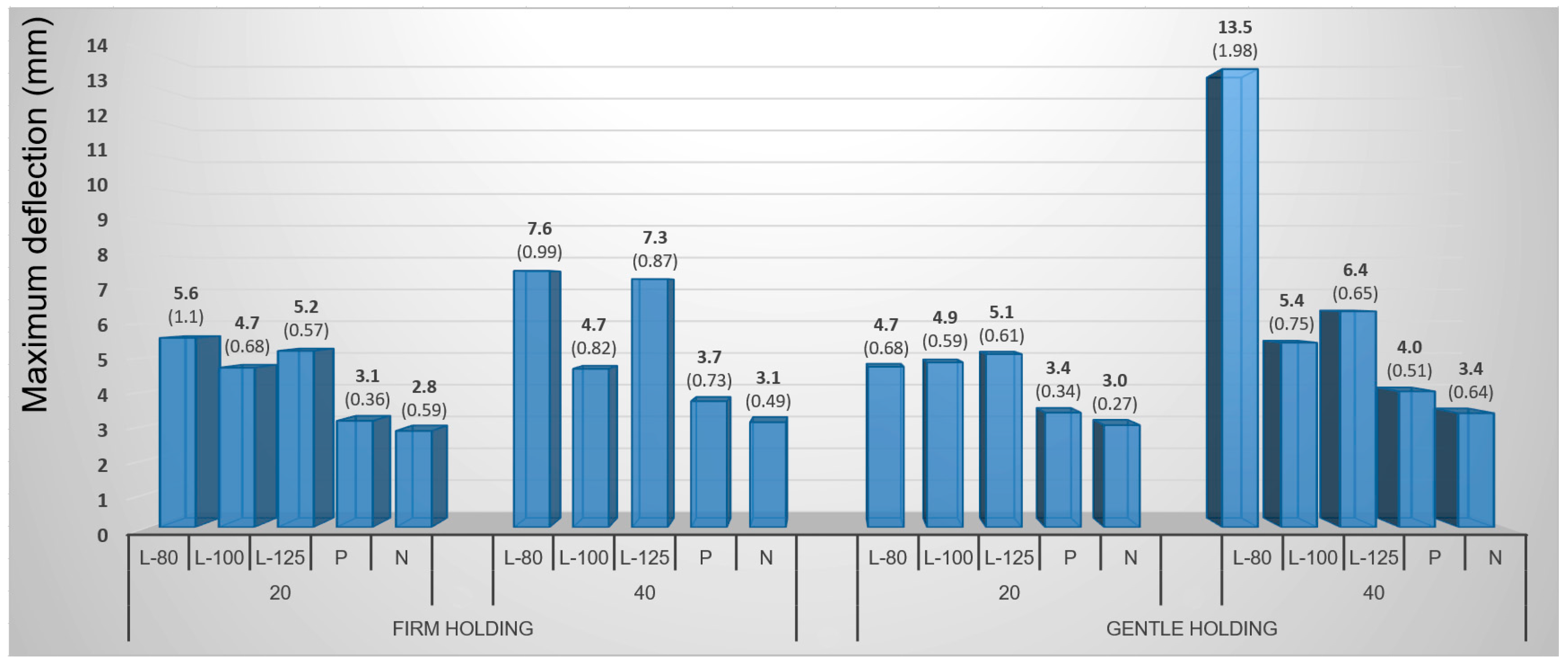
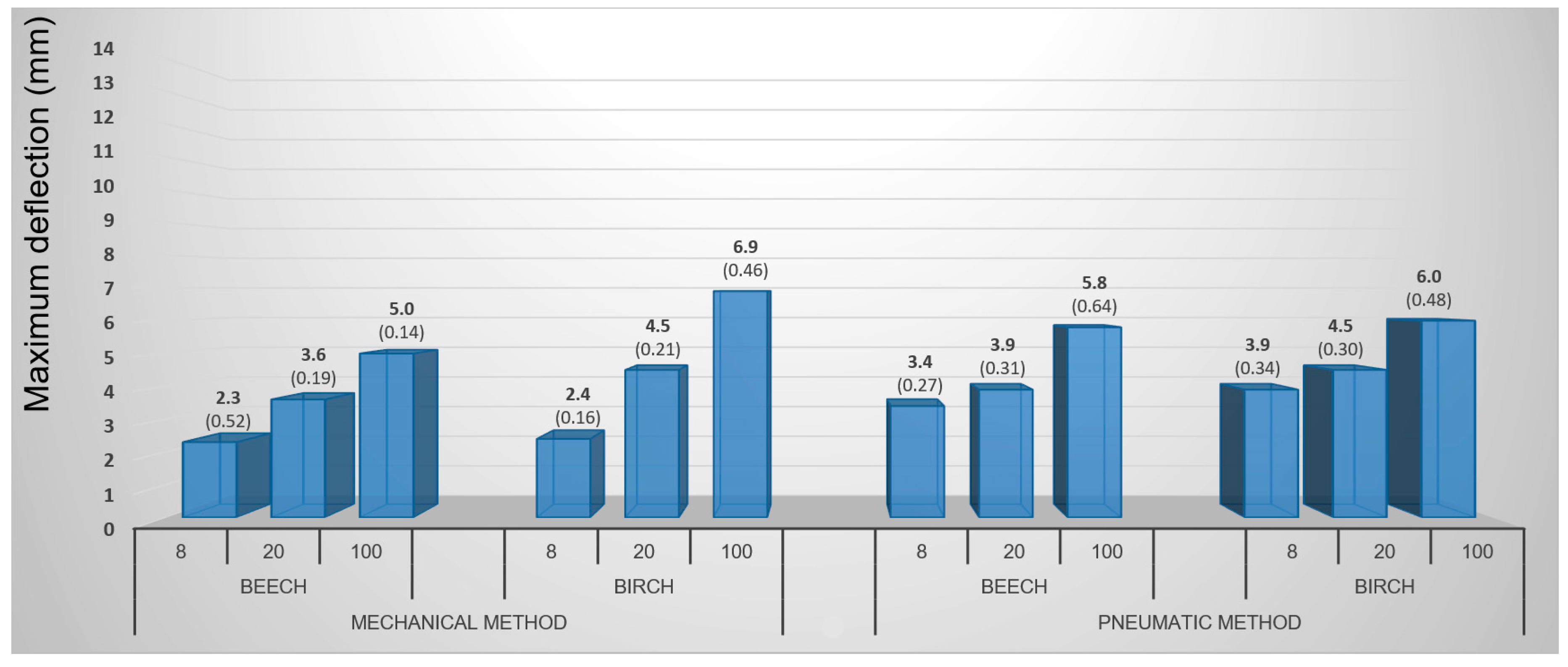
3.1.2. Mechanical Method with Lamination Treatment and Steaming
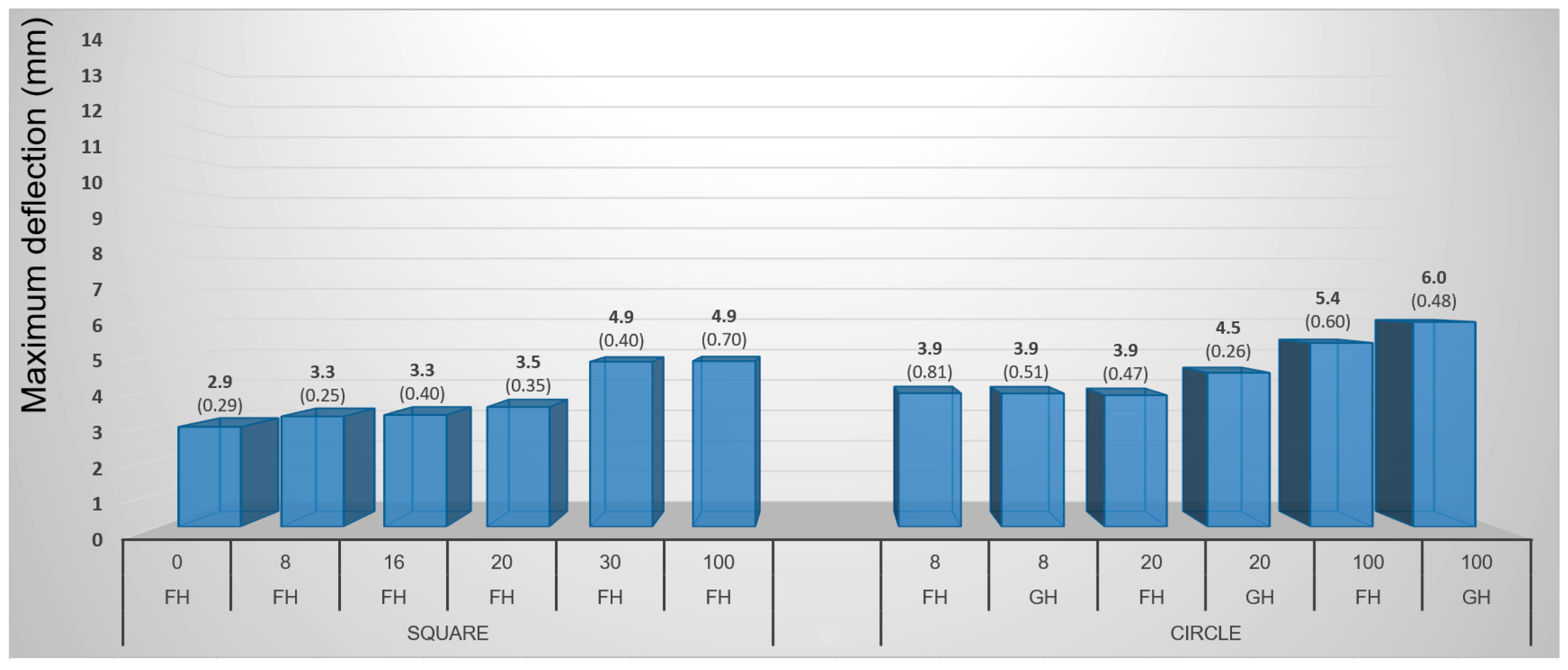
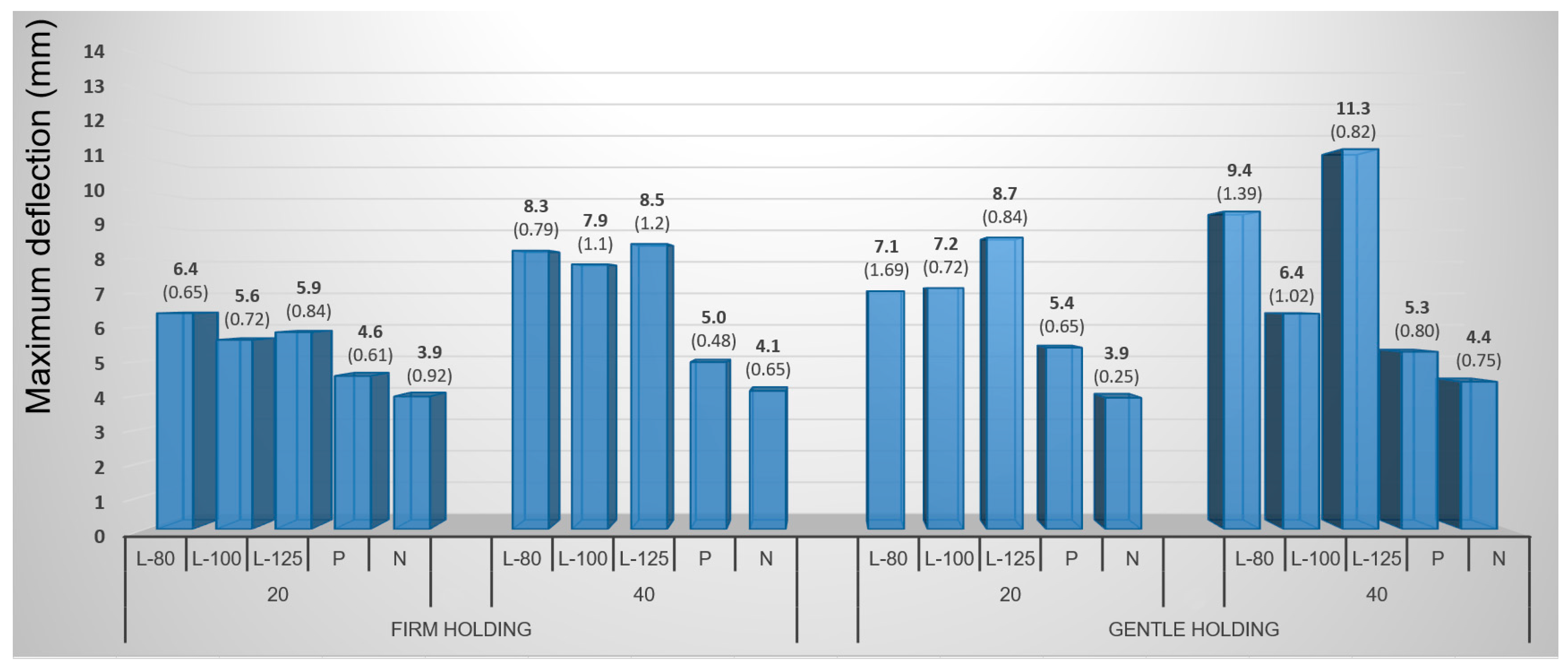
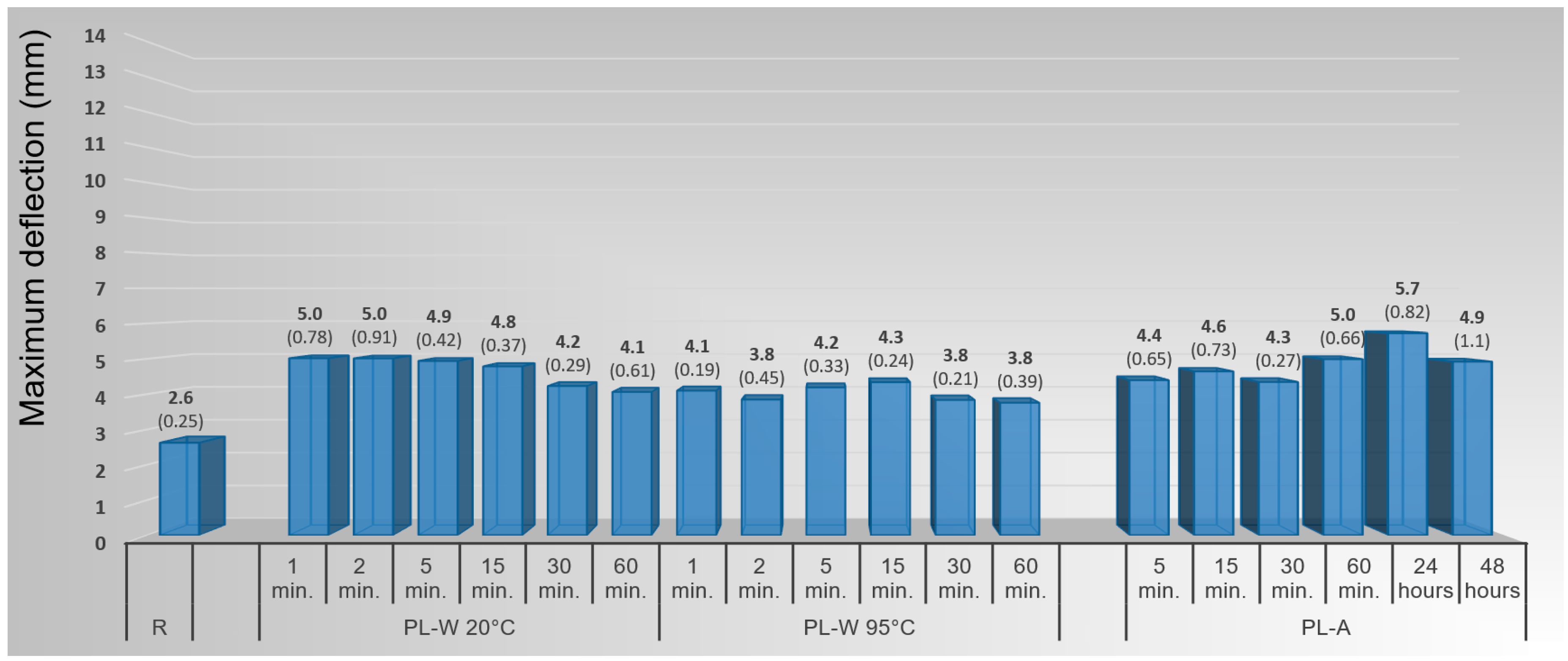
3.1.3. Mechanical Method with Plasticizing by Water and Ammonia
3.1.4. Pneumatic Method
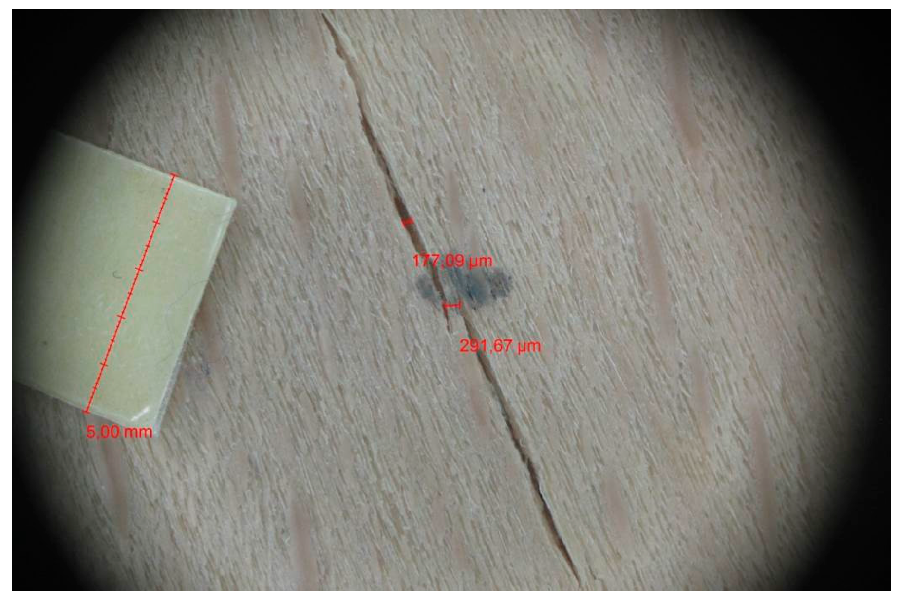
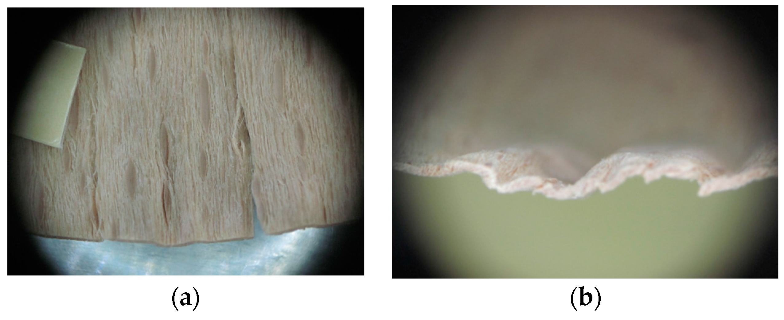
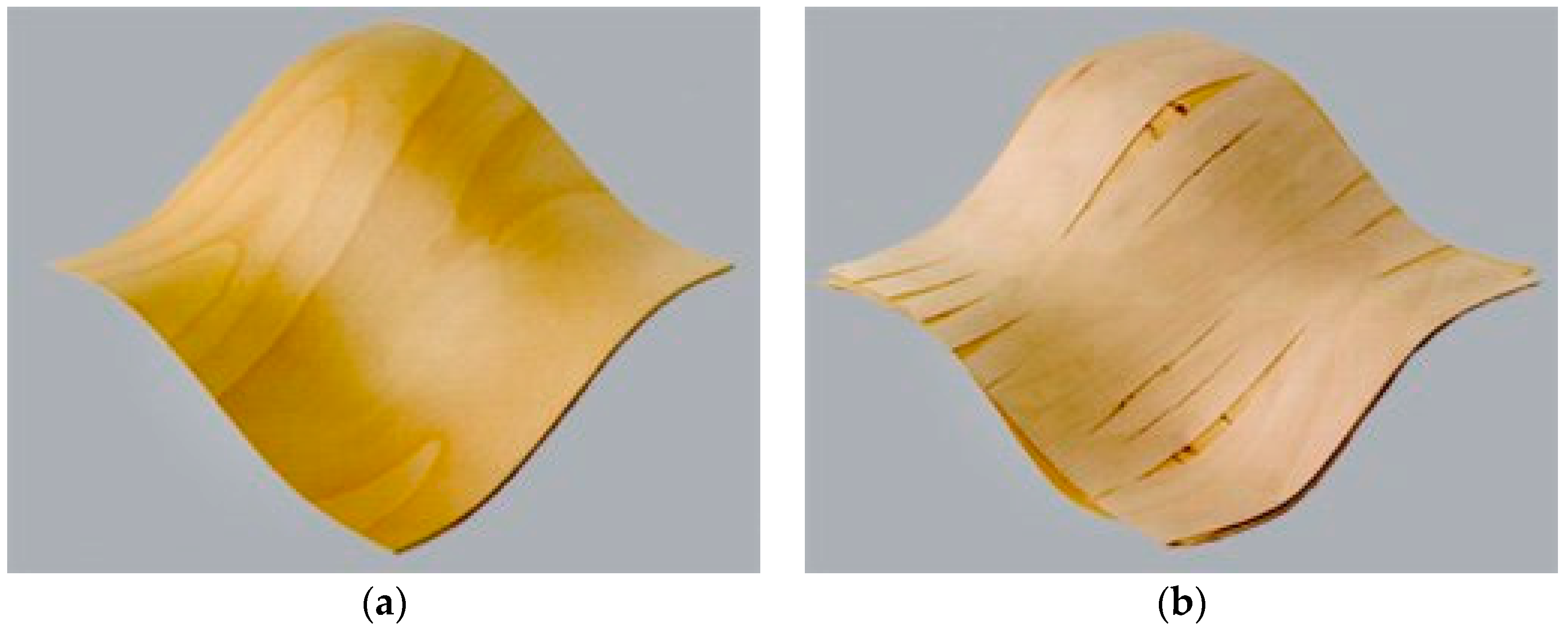
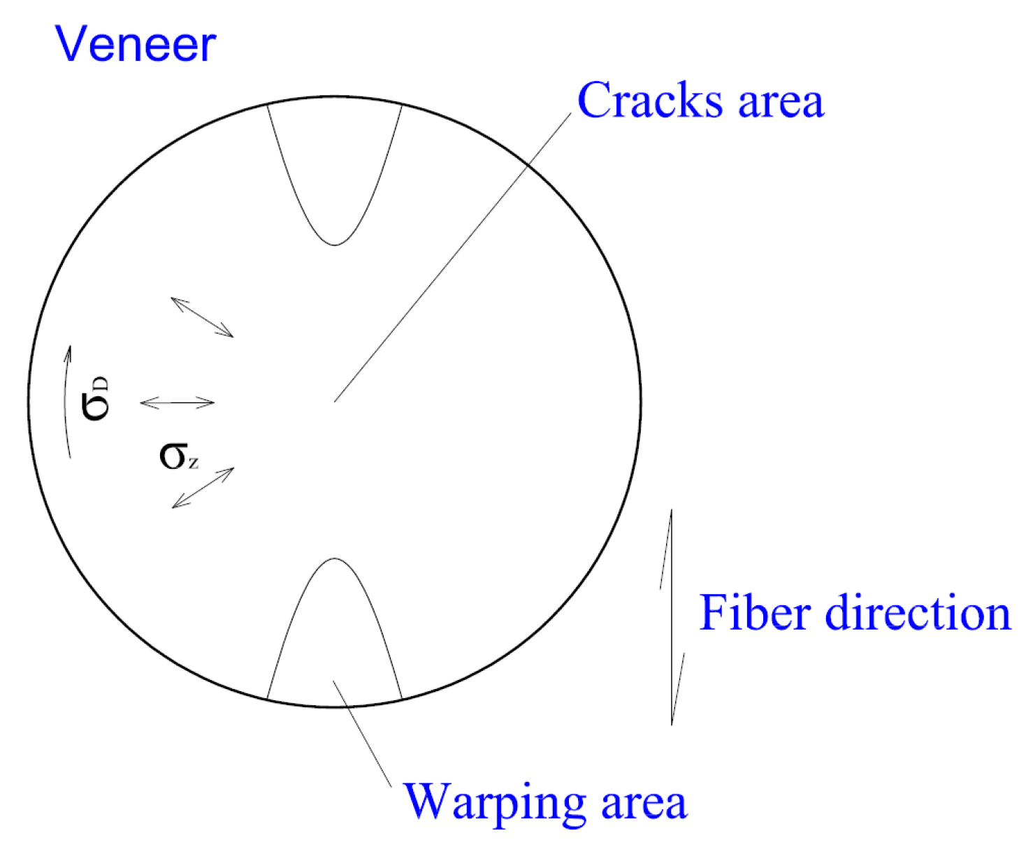
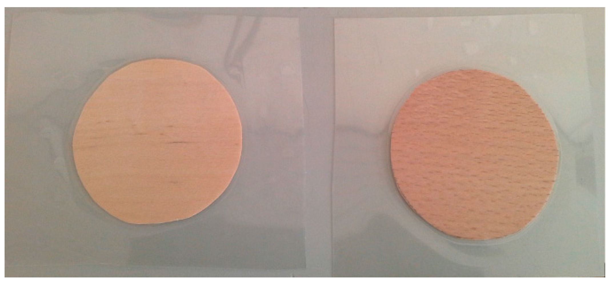
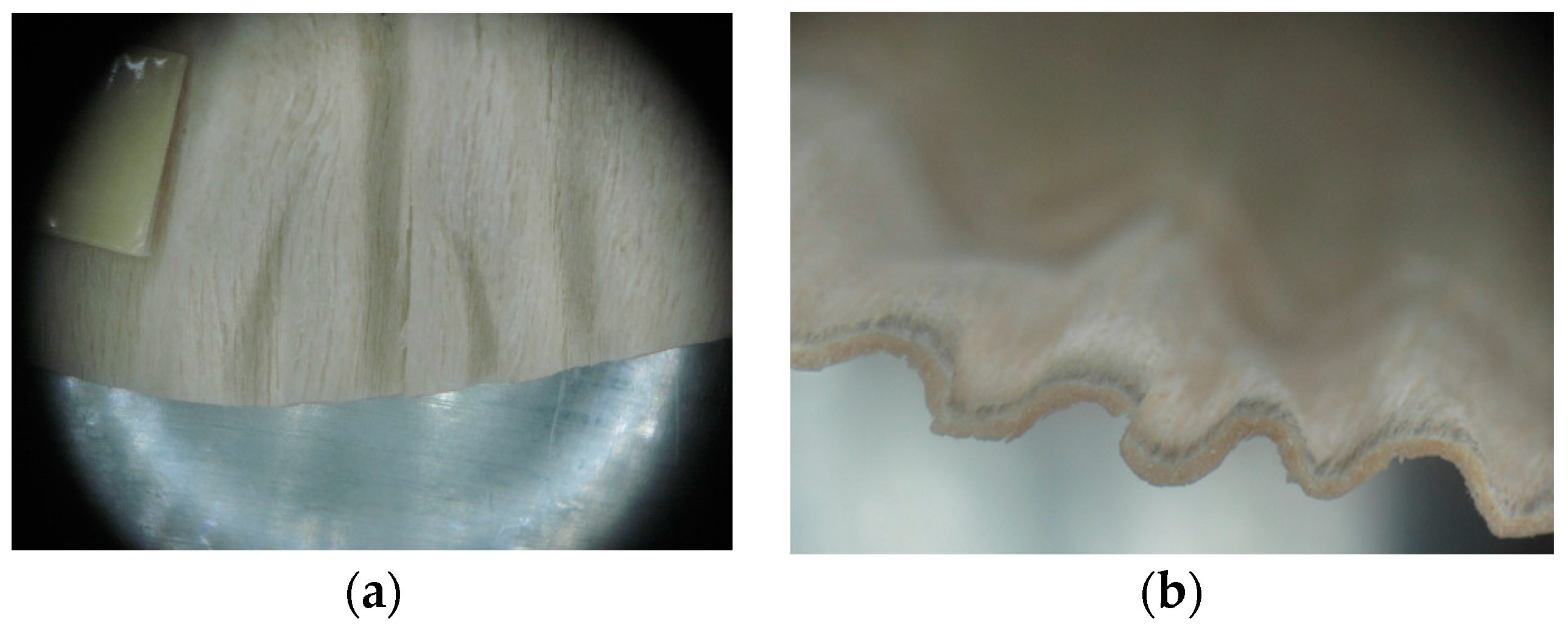
3.2. Warping and Micro Cracks
4. Conclusions
Acknowledgments
Author Contributions
Conflicts of Interest
References
- Wagenführ, A.; Buchelt, B. Untersuchungen zum materialverhalten beim dreidimensionalen Formen von Furnier. Holztechnologie 2005, 46, 13–19. (In German) [Google Scholar]
- Danzer Veneer Europe GmbH. 3-D Veneers—Processing/Technology 2016. Available online: http://www.danzer.cz/Processing-Technology.3064.0.html (accessed on 20 April 2016).
- Wagenführ, A.; Buchelt, B.; Pfriem, A. Material behaviour of veneer during multidimensional molding. Holz als Roh-und Werkst. 2006, 64, 83–89. [Google Scholar] [CrossRef]
- Navi, P.; Sandberg, D. Thermo-Hydro-Mechanical Processing of Wood, 1st ed.; EPFL Press: Lausanne, Switzerland, 2012; p. 376. [Google Scholar]
- Peres, M.L.; de Delucis, R.Á.; Gatto, D.A.; Beltrame, R. Mechanical behavior of wood species softened by microwave heating prior to bending. Eur. J. Wood Wood Prod. 2016, 74, 143–149. [Google Scholar] [CrossRef]
- Kutnar, A.; Kamke, F.A. Compression of wood under saturated steam, superheated steam, and transient conditions at 150 °C, 160 °C, and 170 °C. Wood Sci. Technol. 2012, 46, 73–78. [Google Scholar] [CrossRef]
- Yildiz, S.; Gezer, E.D.; Yildiz, U.C. Mechanical and chemical behavior of spruce wood modified by heat. Build. Environ. 2006, 41, 1762–1766. [Google Scholar] [CrossRef]
- Gašparík, M.; Barcík, Š. Impact of plasticization by microwave heating on the total deformation of beech wood. BioResources 2013, 8, 6297–6308. [Google Scholar] [CrossRef]
- Pařil, P.; Brabec, M.; Maňák, O.; Rousek, R.; Rademacher, P.; Čermák, P.; Dejmal, A. Comparison of selected physical and mechanical properties of densified beech wood plasticized by ammonia and saturated steam. Eur. J. Wood Wood Prod. 2014, 72, 583–591. [Google Scholar] [CrossRef]
- Weigl, M.; Müller, U.; Wimmer, R.; Hansmann, C. Ammonia vs. thermally modified timber—Comparison of physical and mechanical properties. Eur. J. Wood Wood Prod. 2012, 70, 233–239. [Google Scholar] [CrossRef]
- Rousek, R.; Rademacher, P.; Brabec, M.; Dejmal, A.; Horníček, S.; Baar, J.; Šprdlík, V. Beech wood modification with ammonia gas—Improved properties. PRO LIGNO 2015, 11, 230–238. [Google Scholar]
- Sandberg, D.; Haller, P.; Navi, P. Thermo-hydro and thermo-hydro-mechanical wood processing: An opportunity for future environmentally friendly wood products. Wood Mater. Sci. Eng. 2013, 8, 64–88. [Google Scholar] [CrossRef]
- Physical and Mechanical Properties of Wood—Test Methods for Small Clear Wood Samples—Part 1: Determination of Moisture Content for Physical and Mechanical Tests; ISO 13061-1; International Organization for Standardization: Geneva, Switzerland, 2014.
- Metallic Materials—Sheet and Strip—Erichsen Cupping Test; EN ISO 20842; European Committee for Standardization: Brussels, Belgium, 2013.
- Zemiar, J.; Fekiač, J. Testing and evaluation of 3D-formability of veneers. Acta Fac. Xylologiae Zvolen 2014, 56, 31–38. [Google Scholar]


| Diameter of Punch (mm) | Diameter of Circular Samples (mm) | Dimensions of Square Samples (mm) |
|---|---|---|
| 20 | ø 60 | 60 × 60 |
| 40 | ø 80 | 80 × 80 |
| 80 | ø 100 | 100 × 100 |
| Parameter | Equilibrium Moisture Content | |||||
|---|---|---|---|---|---|---|
| 0% | 8% | 16% | 20% | 30% | 100% | |
| Air moisture (%) | 0 | 40 | 78 | 87 | 96 | soaking in water |
| Temperature (°C) | 103 ± 2 | 20 | ||||
| Method Condition | Mechanical | Pneumatic | |||||||
|---|---|---|---|---|---|---|---|---|---|
| General Basic Mechanical Method | I. Comparison Group | II. Comparison Group | General Basic Pneumatic Method | ||||||
| No Treatment | Lamination | Plasticizing by Steam | No Treatment | Plasticizing by Water | Plasticizing by Ammonia | ||||
| Wood species | European beech | European beech | European beech | European beech | European beech | European beech | European beech | European beech | European beech |
| Silver birch | Silver birch | Silver birch | Silver birch | Silver birch | Silver birch | ||||
| Moisture content | 0% | 16% | 16% | 16% | 16% | 16% | 16% | 0% | 8% |
| 8% | 8% | ||||||||
| 16% | 16% | 20% | |||||||
| 20% | 20% | ||||||||
| 30% | 30% | 100% | |||||||
| 100% | 100% | ||||||||
| Shape of sample | Square | Circle | Circle | Circle | Circle | Circle | Circle | Square | Circle |
| Circle | |||||||||
| Diameter of pressing punch | 20 mm | 20 mm | 20 mm | 20 mm | 40 mm | 40 mm | 40 mm | - | - |
| 40 mm | |||||||||
| 40 mm | 40 mm | 40 mm | |||||||
| 80 mm | |||||||||
| Thickness of lamination foil | - | - | 80 µm | - | - | - | - | - | - |
| 100 µm | |||||||||
| 125 µm | |||||||||
| Type of sample fixation | gentle holding | firm holding | firm holding | firm holding | firm holding | firm holding | firm holding | firm holding | firm holding |
| gentle holding | gentle holding | gentle holding | gentle holding | ||||||
| Water/steam temperature | - | - | - | 95 °C | - | 20 °C | 20 °C | - | - |
| 95 °C | |||||||||
| Plasticizing time | - | - | - | 15 min. | - | 1 min | 5 min | - | - |
| 2 min | 15 min | ||||||||
| 5 min | 30 min | ||||||||
| 15 min | 60 min | ||||||||
| 30 min | 24 h | ||||||||
| 60 min | 48 h | ||||||||
| Crack and warping evaluation | No | Yes | Yes | Yes | No | No | No | No | No |
| Number of samples * | 720 | 80 | 240 | 80 | 10 | 120 | 60 | 120 | 120 |
| Treatment Type | Firm Holding | Gentle Holding | ||
|---|---|---|---|---|
| Beech | Birch | Beech | Birch | |
| L-80 | 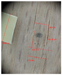 | 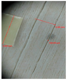 | 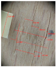 | 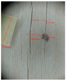 |
| L-100 | 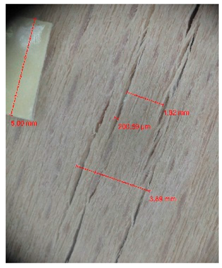 | 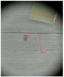 | 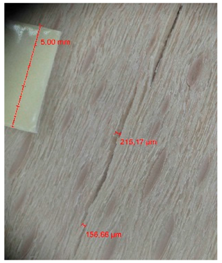 | 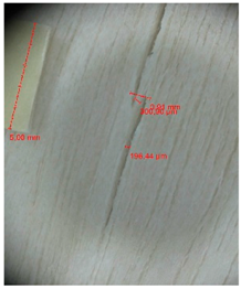 |
| L-125 |  |  |  |  |
| P | 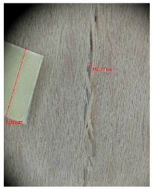 | 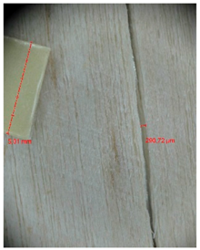 | 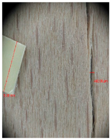 |  |
| N | 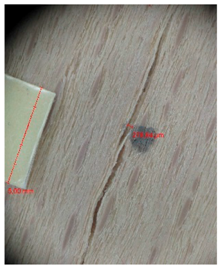 | 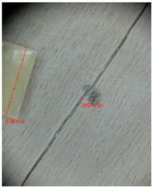 |  |  |
| Treatment Type | Firm Holding | Gentle Holding | ||
|---|---|---|---|---|
| Beech | Birch | Beech | Birch | |
| L-80 |  |  | 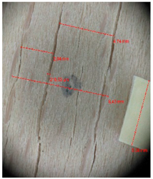 |  |
| L-100 | 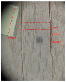 | 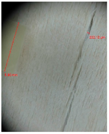 |  | 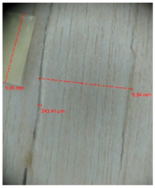 |
| L-125 | 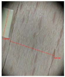 | 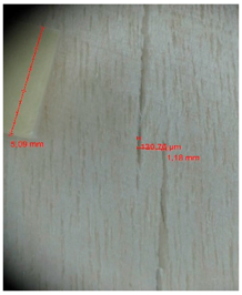 | 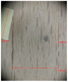 |  |
| P |  |  |  |  |
| N | 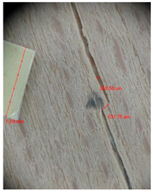 | 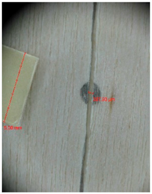 | 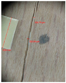 | 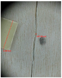 |
© 2017 by the authors. Licensee MDPI, Basel, Switzerland. This article is an open access article distributed under the terms and conditions of the Creative Commons Attribution (CC BY) license ( http://creativecommons.org/licenses/by/4.0/).
Share and Cite
Gaff, M.; Gašparík, M. 3D Molding of Veneers by Mechanical and Pneumatic Methods. Materials 2017, 10, 321. https://doi.org/10.3390/ma10030321
Gaff M, Gašparík M. 3D Molding of Veneers by Mechanical and Pneumatic Methods. Materials. 2017; 10(3):321. https://doi.org/10.3390/ma10030321
Chicago/Turabian StyleGaff, Milan, and Miroslav Gašparík. 2017. "3D Molding of Veneers by Mechanical and Pneumatic Methods" Materials 10, no. 3: 321. https://doi.org/10.3390/ma10030321
APA StyleGaff, M., & Gašparík, M. (2017). 3D Molding of Veneers by Mechanical and Pneumatic Methods. Materials, 10(3), 321. https://doi.org/10.3390/ma10030321