1. Introduction
In the rural areas of developing countries, one of the most critical issues is the preservation of food [
1]. Settlements located in such areas are typically not served by the grid or—if they are—electricity is available only for a few hours per day [
2,
3]. Several stand-alone solutions for food preservation have been developed with the aim to solve this problem; some of them use solar thermal collectors as heat sources [
4,
5,
6,
7] working on sorption refrigeration (adsorption or absorption), others are powered by fossil fuels, such as kerosene or liquid petroleum gas (LPG) [
8]. Since, in recent years, a strong reduction occurred in the manufacturing cost of photovoltaic (PV) modules [
9,
10] and small-size direct current (DC) compressors are commercially available at reasonable prices, the development of PV refrigerators can be considered affordable compared to other solutions [
11].
To this extent, some solutions can be found on the market [
12,
13,
14], although the available products are usually costly [
15] for different reasons. For example, the use of batteries for energy storage in the case of electric refrigeration, and the use of complex solutions involving the absorption cycle in the case of solar thermal application—combined with the fact that the components are usually manufactured in developed countries and shipped as ready-to-use systems—substantially increases the final market cost [
16,
17].
In general, a systematic comparison of the main technologies used for food refrigeration in developing countries and documented in literature is presented in the
Table 1 [
11,
15,
16,
17,
18,
19,
20,
21,
22]. The information refers to small/medium size refrigerators for food/vaccine preservation and the reference costs include the accessories required to operate the system (e.g., PV modules, burner, etc.).
For such reasons, this work presents the characterization of an innovative solution, which was preliminarily developed within a wider research activity [
23] aimed at the application of PV refrigeration in Africa’s tropical-equatorial belt. In detail, the system proposed is modular, battery-free, and can be self-constructed on site using local materials and manpower. Moreover, the use of local materials, combined with technological parts manufactured in developed countries, could produce the following advantages:
Low market price compared with products currently available in Africa, since shipping and manufacturing costs are strongly reduced; the objective is to maintain the final cost of the system below 1000 € for a standard module with 250 L of net capacity;
High availability; the system can be easily repaired by local people; in addition, full operability without solar power is ensured by the thermal storage; the aim of the research is to ensure the air temperature inside the fridge is always below 10 °C even after 48 h without solar radiation;
Reduction in the environmental impact during and at the end of the working life; in the proposed system all of the components can be re-used or recycled;
Active participation of the population during the manufacturing phase, in order to achieve economic benefits and improve technical knowledge. The entire system can be assembled locally without specific expertise or technical equipment. Importing ready-to-use products from developed countries has, in fact, a negative impact on the local technical knowledge.
In addition, the careful selection of the materials for the structure of the refrigerator and the use of specific guidelines on food preservation will guarantee high hygienic performance.
The general aim of the research is, thus, to realize a modular kit, in order to economically and effectively meet the needs of different contexts, taking into specific consideration Africa’s tropical regions. In fact, such areas are the most investigated for the distribution of the technology proposed, and—in particular—a village located in Northwest Cameroon was selected as a case study for the final application. In that village, in the last phase of the research project, the refrigerator will be installed and monitored in its operational environment.
Within such a context, this work describes the first experimental validation of the technology, carried out by means of the construction of a prototype of the system, realized at the Politecnico di Milano (Milan, Italy), and the subsequent testing and monitoring activity, which started in September 2015, as described below.
2. System Description
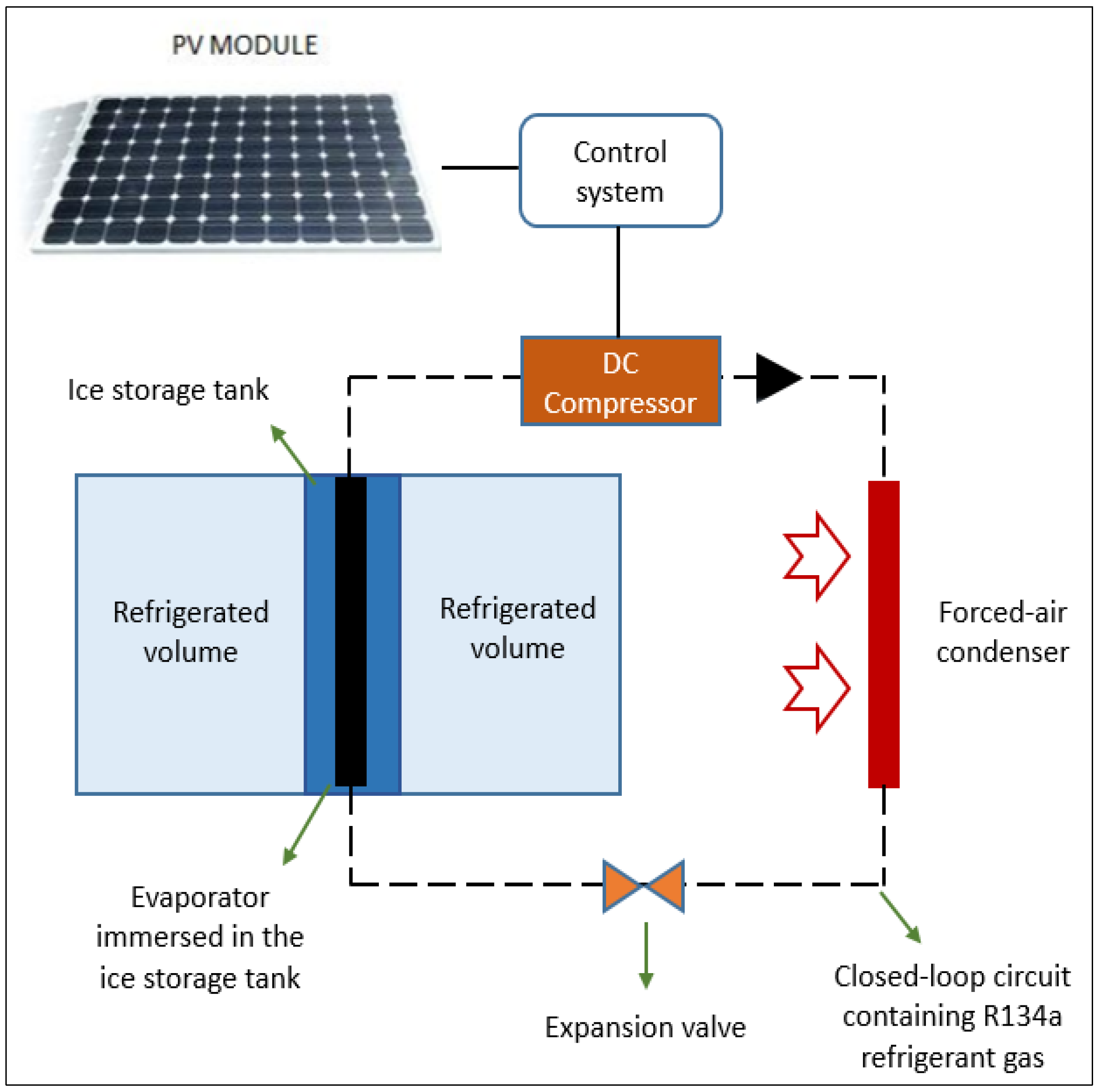
The PV refrigerator is based on a compression cycle and is composed of the following elements: A PV module, a DC compressor with a forced-air-cooled condenser, a roll-bond evaporator, a thermally-insulated envelope containing ice storage, an expansion valve, and the control system (
Figure 1). The main technical specifications of the components are reported in
Table 2.
The evaporator is placed inside a mass of water (ice thermal storage). Such water, once frozen, ensures an optimal storage temperature of the refrigerated volume even without solar radiation.
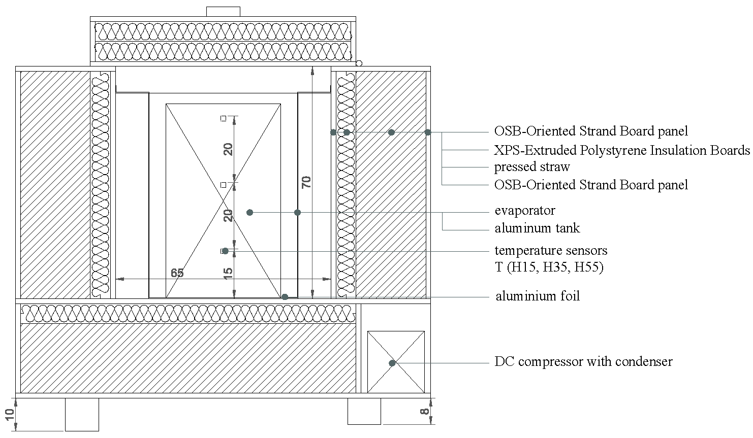
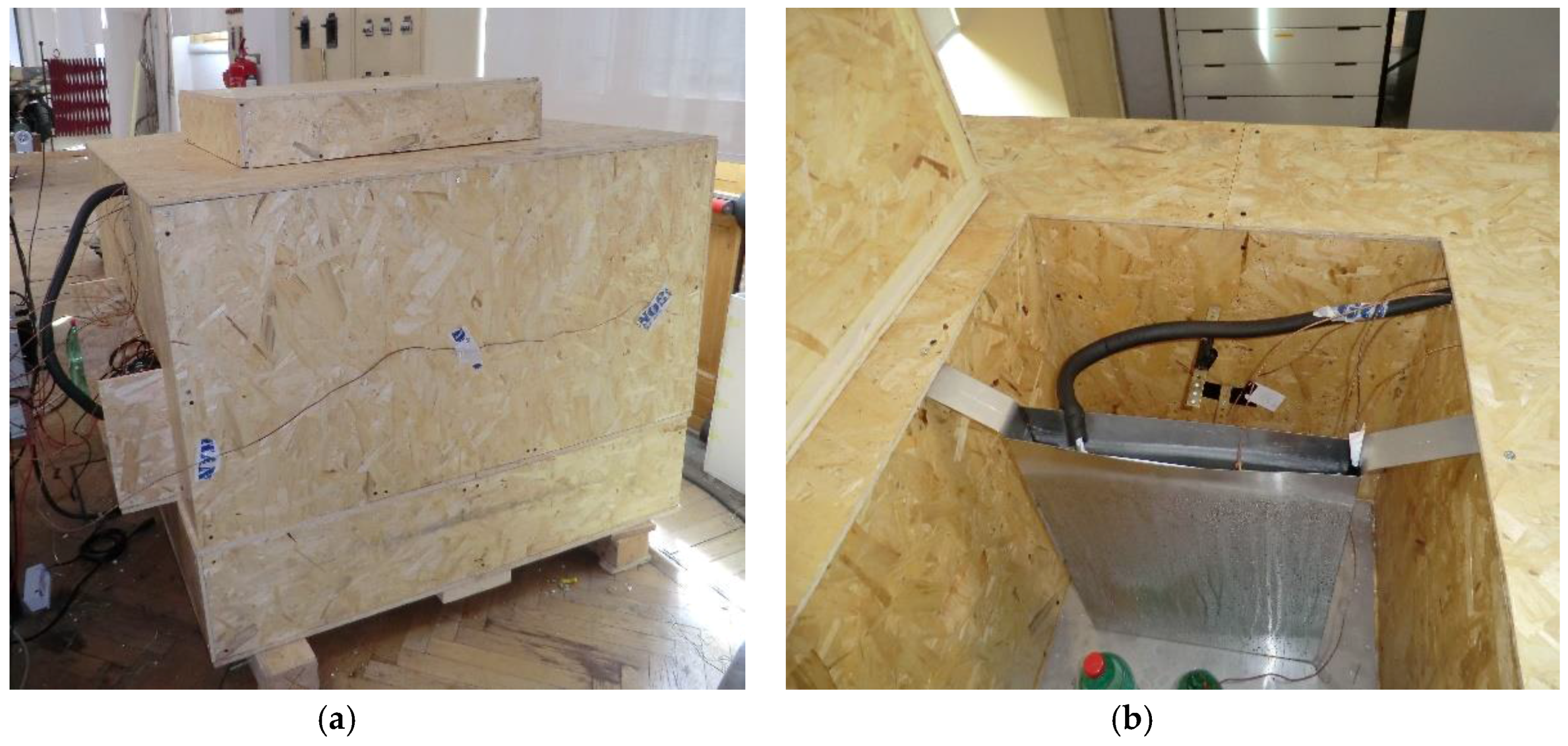
The prototype version of the PV-based refrigerator realized at the Politecnico di Milano is a wooden box with a net capacity of approximately 295 L and an internal dimension of the refrigerated volume equal to 65 cm × 70 cm × 65 cm (L × H × W).
For the realization of the envelope, materials available in Italy were selected, ensuring the same thermo-physical properties of the ones that can be found in Cameroon. The volume of the refrigerator and the ice storage are the ones designed.
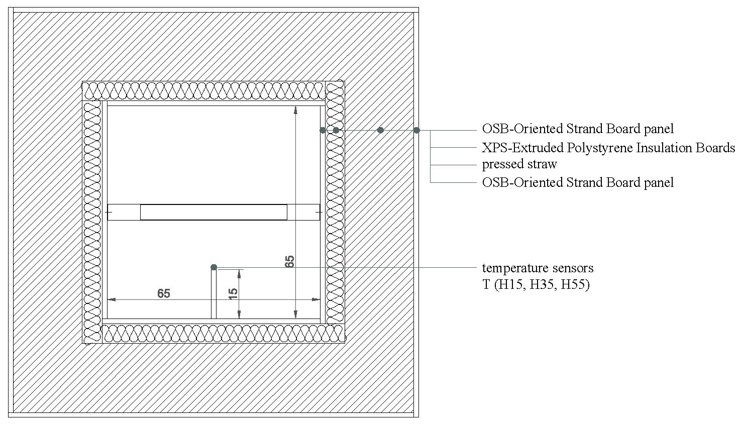
In detail, the envelope of the prototype refrigerator is composed of:
Internal layer: oriented strand board (OSB) panel (1 cm thick);
Thermal insulation: wood-fiber insulation (6 cm thick) and compressed straw (21 cm thick);
External layer: OSB panel (1 cm thick).
In addition, the box has an internal waterproof layer made of a plastic protecting coating, which is applied like a varnish; the bottom of the refrigerated volume is, instead, covered by an aluminum foil (1 mm). The box is lifted off the ground in order for it to stay dry and to ensure a slight gradient that allows internal condensation water to leave through the specially-designed drain channel.
Inside the refrigerated volume, an aluminum tank is placed, to be used as an ice storage with dimension 45 cm × 62 cm × 5 cm (L × H × W); the capacity of the tank is about 15 L and the volume of the contained water was set equal to 12.5 L, in order to provide roughly 72 h of proper operability without solar power.
The box is equipped with a hinged cover on the top, made with the same materials.
Figure 2 shows a vertical and a horizontal section of the prototype while in
Figure 3 the external and internal views of the system used for testing purposes are shown.
3. Energy Model
To assess the energy performance of the system, a simplified energy model was developed. The model estimates the mean air temperature inside the refrigerator and the temperature of the water in the storage container, on the basis of the boundary conditions, assuming the initial conditions are known. The model is based on the energy balances of the internal air and the whole refrigeration system, solved at any desired time step. The thermal inertia of the envelope is considered negligible, since it is realized with lightweight insulation materials.
In addition, in order to define the energy balance of the refrigerator, the items introduced in the fridge to be cooled—such as food and beverages—are considered to be, at each time step, at the same temperature of the surrounding air. It is, thus, assumed that an instantaneous heat transfer between the internal air and the food/beverage occurs. Otherwise, the specific heat transfer coefficient of the food/beverage placed inside the fridge should be known for every kind and size of the same.
This simplification is reasonable insofar that the thermal conductivity and the heat transfer area of the food/beverages inside the fridge are high (e.g., aluminum cans, small fruits rich of water, etc.) and the transient condition during which the load is cooled at the set-point temperature is not considered relevant for the specific scope of this work. The aim of the model is, in fact, to assess the proper functioning of the system (i.e., to maintain the internal set-point temperature in steady state conditions), overlooking the time needed to cool the load.
In detail, the initial/boundary conditions which have to be known are the following:
The external air temperature at each time step, Text,n;
The average irradiance on the module surface at a certain time step In, in W/m2;
The internal air temperature and the water temperature in the storage (Tint,0 and Tw,0) at the initial time t0;
The specific heat, cpload, and the mass, mload, of the items placed inside the refrigerator; and
If there are openings of the refrigerator during a certain time interval.
We assumed that all the quantities of energy removed from the insulated volume of the refrigerator and transferred to the external environment are positive values.
3.1. Thermal Balance of Internal Air
The internal air temperature
Tint,1 and the water temperature inside the energy storage
Tw,1 are calculated on the basis of the thermal balance of the energy storage, defined in the following equation:
which means that, during a certain time interval Δ
t = t1 −
t0, the amount of energy released by the thermal storage
Qsto,0–1 in the air surrounding the refrigerator is equal to the sum of the heat loss through the envelope
Qenv,0–1, the thermal energy adsorbed by the thermal load inside the refrigerator
Qload,0–1, the thermal energy absorbed by the air inside the refrigerator
Qair,0–1, and the thermal energy eventually dissipated during the openings of the cover
Qo,0–1.
By making explicit all the terms, the equation becomes:
where
k is conservatively set equal to 0.5 in case of openings at a certain time step or 0 if there are no openings. The two unknown quantities are
Tint,1 and
Tw,1, which can be determined by also considering the thermal balance of the whole system, as described below.
3.2. Thermal Balance of the System
The global thermal balance of the refrigerator can be described with the following relation:
which means that, during a certain time interval Δ
t = t1 −
t0, the amount of energy removed by the evaporator in the thermal storage
Qeva,0–1 is equal to the sum of the thermal energy dispersed by the envelope of the fridge
Qenv,0–1, the thermal energy adsorbed by the thermal load placed inside the fridge
Qload,0–1, the thermal energy absorbed by the internal air
Qair,0–1, the thermal energy dissipated during the openings
Qo,0–1, and the thermal energy absorbed by the water in the thermal storage
Qw,0–1.
By making explicit all the terms, the equation becomes:
In Equation (4),
Qeva,0–1, which is the thermal energy removed by the evaporator, is calculated according to the following relation:
where:
and:
Text,rif is equal to 32 °C, according to the temperature defined by the UNI EN 12900 [
24], used by the manufacturer to determine the reference coefficient of performance (COP) of the compressor.
Equations (6) and (7) result from the interpolation of experimental data provided by the manufacturer of the compressor.
It must be noted that the mean temperature of the evaporator within the time step can be calculated as:
The condition in Equation (8) was determined experimentally, and it is different from the usual case of a roll-bond evaporator operating in air, when
Teva is usually 10–15 °C lower than the air temperature [
25,
26] due to a lower heat exchange coefficient of the plate.
The minimum power required to start the compressor is, in fact, equal to approximately 45 W and the average electric power required during the operation is 55 W, thus assuming a 250 W
p PV module, when
In is higher than 250 W/m
2 the generated power is assumed sufficient to run the compressor [
27]. Hence:
In detail, when the compressor runs, the mean value of 55 W is referred to 3000 revolutions per minute (RPM), a mean evaporating temperature of −5 °C, and a mean environmental temperature of 25 °C. Such conditions can be considered as a reference for the system. In addition to the 55 W needed by the compressor, a 5 W supplementary power for the condenser fan has to be considered.
It must be noted that, during the laboratory experimentation, the compressor was powered by a DC power supply according to a working profile which simulates the average hours of useful solar radiation in the selected application context (Cameroon). Thus, Ecom is a measured quantity.
The only unknown variables in Equations (2) and (4) are Tw,1 and Tint,1, which can consequently be calculated combining the two equations. The process can be repeated to calculate the two temperatures at the following time steps, until Tw,n = 0 °C is reached.
As the water in the storage starts to freeze, the unknown quantity becomes the water mass that solidifies during a certain time step, while the water temperature is considered constant during the freezing process (
Tw,n =
Tw,n+1 = 0 °C). Equation (4) must also include the latent load absorbed by the water during the freezing process, and becomes:
As in the previous situation, there are two unknown quantities (Tint,n+1 and mw,ice,n), and two available Equations (2) and (10). Thus, the system can be solved and Tint,n+1 and mw,ice,n can be calculated.
This process has to be repeated until all of the water mass inside the tank is completely frozen (mw,ice = mw,tot). Subsequently, Equations (2) and (4) must be used to calculate the ice temperature, changing the value of the specific heat of the water and using that of the ice. When the compressor stops, the calculation process remains the same, assuming Qeva,n = 0.
4. Instrumentation and Data Logging
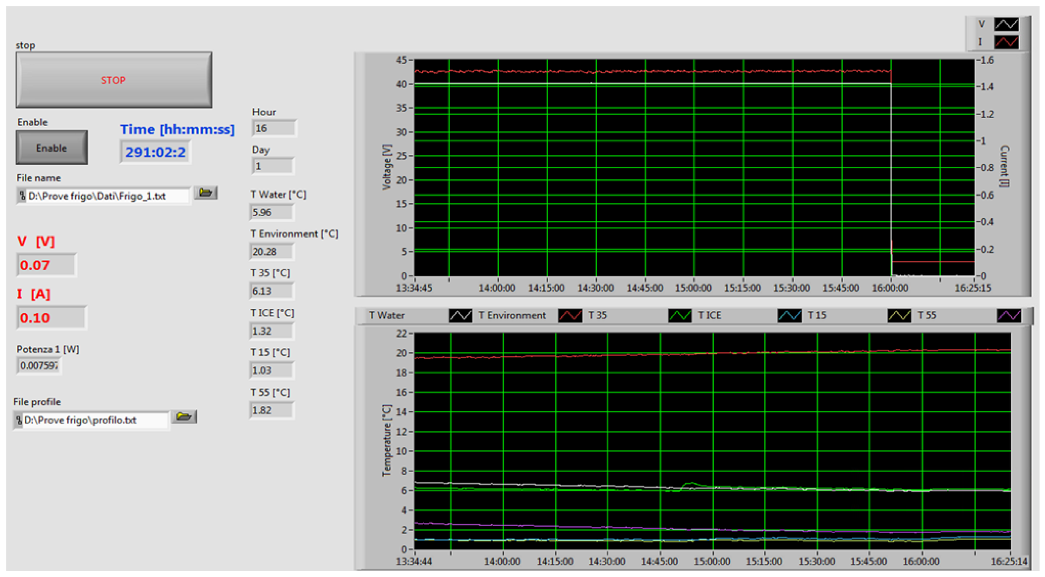
The prototype developed was tested to validate the simulated thermal analysis. For this purpose, an ad hoc testbed was developed. The system allows testing the prototype in actual working conditions. In fact, it permits enforcing a desired power profile over time, thus simulating the behavior of the PV panel in the application context taken into account. The system allows to monitor electrical quantities, voltage, and current, as well as six temperatures.
The system was developed according to a virtual instrument (VI) approach by means of Labview Software (National Instruments, Austin, TX, USA) (
Figure 4).
The PV panel was simulated by means of a DC generator (Sorensen SGI 400-38, AMETEK Programmable Power, San Diego, CA, USA) remotely controlled through a General Purpose Interface Bus (GPIB) connection (
Figure 5). The software provides the set point over the time to the generator. The voltage generated and the flowing current were transduced by means of a voltage divider and a Hall effect transducer. The signals were then acquired by means of 16-bit resolution ADCs (National Instruments, Austin, TX, USA). A sampling frequency of 1280 Hz was used and the samples were averaged over 10 s.
During the test, different temperatures were measured by means of thermocouples (k-type) and dedicated acquisition boards (NI9211). Temperatures were sampled at 1 Hz and the average of ten samples was considered. In particular, the following temperatures were monitored:
Mean water temperature inside the storage (Tw);
Temperature of the air in the environment in which the fridge is located (Text);
Temperature of the air inside the fridge 15 cm from the bottom (Tint,15);
Temperature of the air inside the fridge 35 cm from the bottom (Tint,35);
Temperature of the air inside the fridge 55 cm from the bottom (Tint,55);
Mean temperature of the load inside the fridge (Tload).
The uncertainty of the temperature measurements is 0.4 °C with a coverage factor k = 2.
5. Experimental Results and Model Validation
The simulation model was firstly run considering the reference parameters reported in
Table 3, which correspond to the testing conditions used to monitor the prototype.
It must be specified that the heat loss coefficient of the storage tank and the thermal transmittance of the envelope were experimentally verified according to the following procedure: the water inside the thermal storage was completely frozen and then the compressor was stopped until the mass of ice returned completely to a liquid state. Thus, the time needed for the melting process ∆t is known. During the test, the temperature inside the thermal storage Tw, internal air temperature Tint, and external air temperature were monitored. Knowing the mass of the water inside the thermal storage mw,tot, the heat loss area of the thermal storage tank Ssto, and the heat loss area of the external envelope Senv, it was possible to calculate the two heat transfer coefficients, Usto and Uenv.
The working profile of the compressor during a typical week was defined through the study of the solar radiation measured in Bangang, Cameroon, where the final prototype will be installed. In particular, it was observed that during sunny days there are, on average, 7–8 h of irradiation, sufficient to run the compressor (In is >250 W/m2), while during partially cloudy days there are 4–5 h of viable irradiation. In addition, very few cloudy days with irradiance below 250 W/m2, during which no operation of the compressor is possible, were observed.
According to the elaboration of weather information, the working profile reported in
Table 4 was selected as a reference to test the refrigerator in laboratory conditions.
The first experimental test to validate the theoretical model was started by inserting a thermal load, represented by 9 kg of water (6 × 1.5 L plastic bottles), and running the system according to the pre-defined working profile.
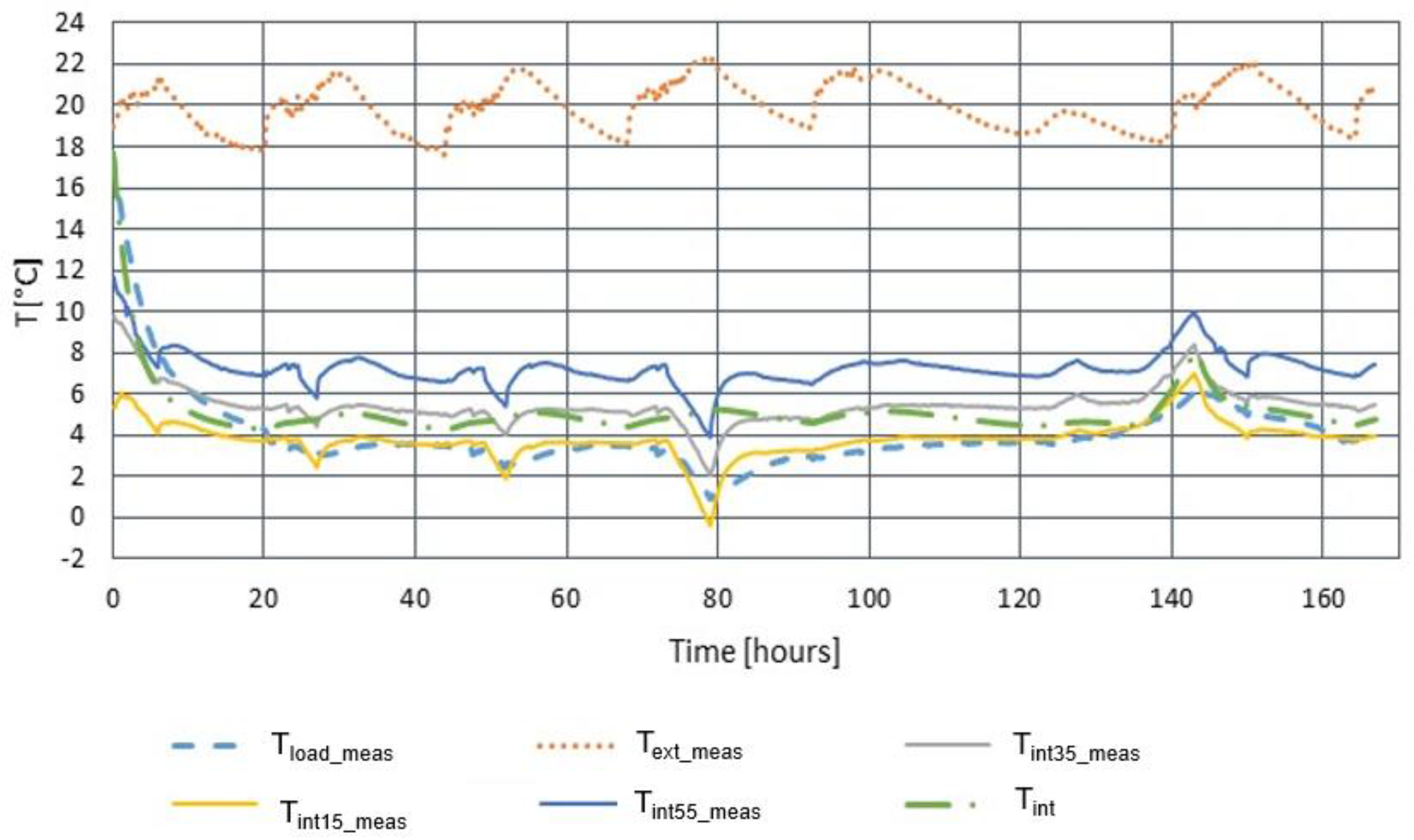
The internal air temperature, calculated, was compared with the temperatures monitored, as shown in
Figure 6.
As it can be observed, the simulated internal air temperature suits well with the temperature measured at the average height of the case (35 cm from bottom), which can be considered representative of the mean air temperature inside the fridge. In detail, the average error between the calculated (Tint) and the measured temperatures (Tint35) is equal to 5.8%. The measured temperature of the load is, instead, on average equal to 4 °C and is very close to the temperature of the air measured 15 cm from the bottom, which is approximately 3.9 °C. The bottles of water were, in fact, placed directly on the bottom of the fridge, therefore they exchanged heat with the coldest part of the air. In general, in any working condition, the mean internal temperature is always around 5.5 °C and the maximum internal temperature, measured at the top of the fridge is, on average, below 8 °C. If the refrigerator remains closed and no additional load is introduced in the course of the two cloudy days, during which the compressor never works, the amount of ice is sufficient to maintain acceptable temperatures of the air and the internal load.
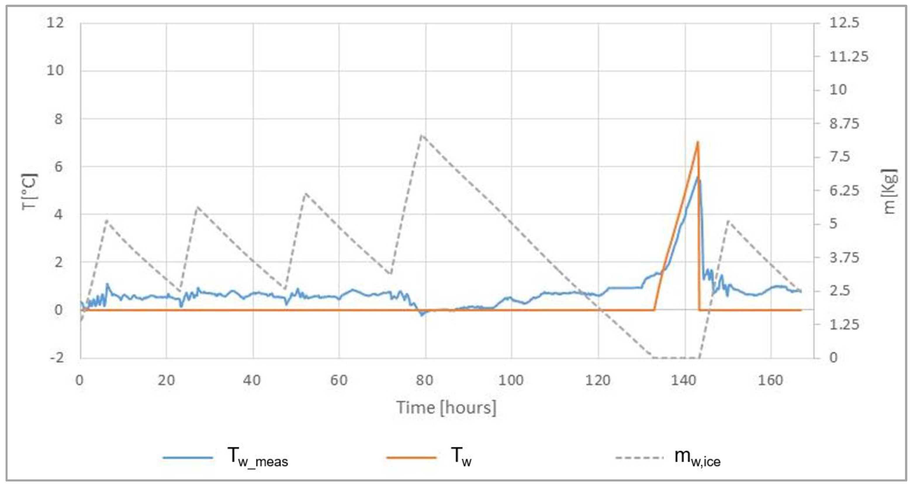
Figure 7 reports the comparison of the average water temperatures simulated and measured in the storage container during a typical working week, along with the amount of frozen water at every time step.
Subsequently, in order to further validate the simulation model, the test was carried out with different kinds of thermal loads placed daily inside the fridge, thus considering the fact that the system is actually to be used as a domestic refrigerator. The amount of new load inserted daily was estimated after the survey carried out in the Bangang village in Cameroon, supposing that the system is used by a group of 3–4 families.
The results obtained are reported in the following
Table 5.
By analyzing the data reported in
Table 5, it is possible to state that, at the end of the transient condition during which the load is cooled at the set-point temperature:
The average air temperature measured inside the refrigerator is always below 10 °C, even if a new thermal load is introduced in the course of the completely cloudy days, when the compressor is off. This result preliminarily confirms the adequate design of the system;
The error between the temperature calculated and that measured is, on average, lower than ±10% and can be mainly attributed to the impossibility to estimate precisely the heat transfer coefficient of the thermal load inside the refrigerator. In any case, as stated before, since the objective of the model is to assess the proper functioning of the system (i.e., to maintain acceptable set-point temperatures in steady state conditions), the approximation introduced can be considered non-relevant.
Finally, it must be noted that, according to the present state of the research, an overall cost of the materials and components needed to realize the refrigerator described in the work is assumed to be around 500 € (excluding value-added tax, shipment costs, and labor). Such results, together with the energy performances above described, can ensure a large penetration of the technology since it can be considered immediately affordable for food retailers and small communities.
6. Conclusions
In this paper, a refrigerator kit—composed of a refrigerated volume, a storage unit, and a PV panel with its control unit—was experimentally tested. For the refrigerator designed, a simplified thermal model is proposed, in order to estimate its operability under the climate conditions of the targeted application context. In addition, a prototype was realized and a test bench was set up in the laboratory. The results of the experimental tests, performed in the lab, confirm the goodness of the thermal model in predicting the steady-state temperature of the food placed inside the refrigerated area as a function of the weather conditions. Experimental results also show that the low-cost and self-constructible refrigerator developed was adequately dimensioned in order to ensure a proper preservation of the food under the typical climate conditions of the Cameroon village that will be the final site of use. In detail, the work demonstrated that the basic module of the refrigerator, with a net capacity of 250 L and an ice storage of 12.5 kg is able to maintain internal temperature below 10 °C even after 48 h of no operation of the compressor and with a new thermal load introduced in the envelope. Finally, the validated model can be successfully used to predict the behavior of the system in different climatic and operational conditions.


 ,
, 


