
A Novel State of Charge Estimation Algorithm for Lithium-Ion Battery Packs of Electric Vehicles


Abstract
:1. Introduction
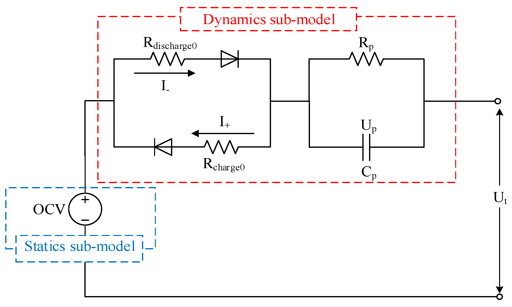
2. Battery Modeling
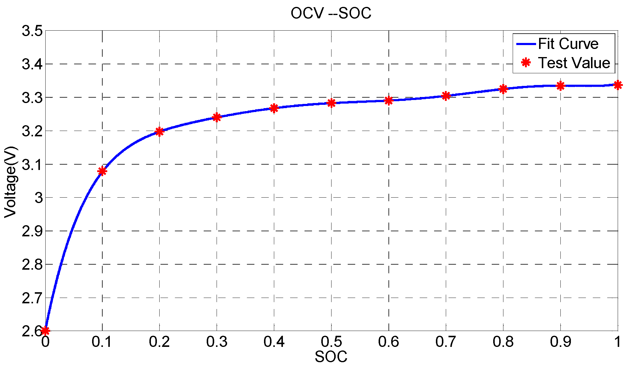
2.1. Battery Cell Modeling
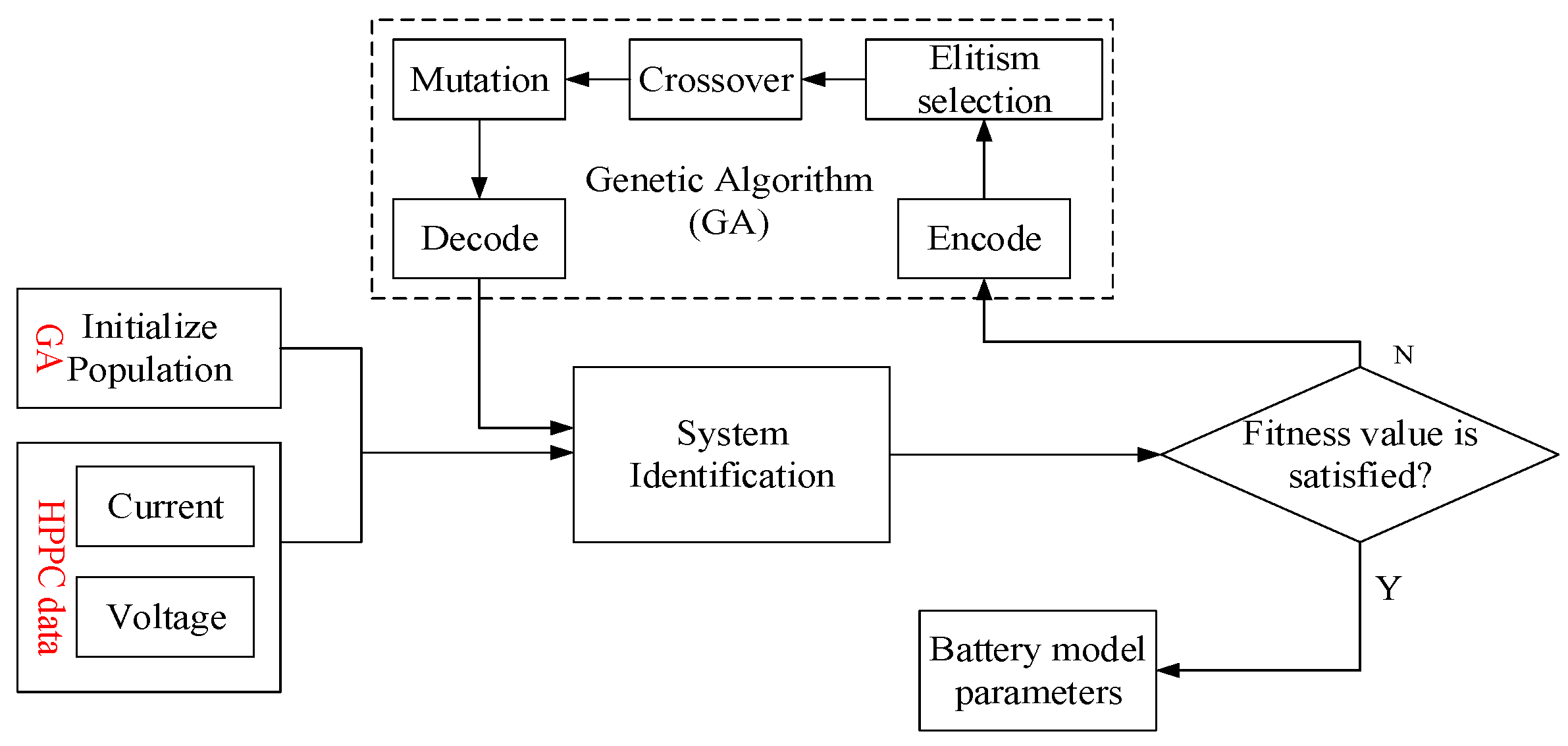
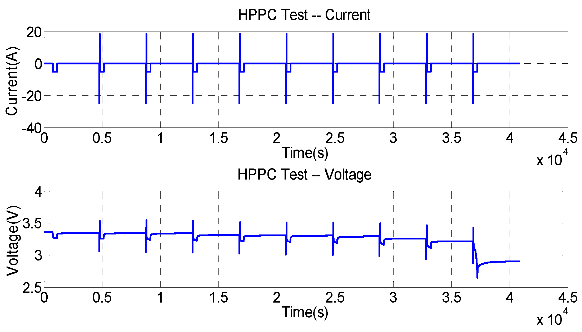
2.2. Parameters Identification Based on Genetic Algorithm
3. State of Charge Estimation Algorithm Design
3.1. The Cell State of Charge Estimation Based on Adaptive Extended Kalman Filter
- (a)
- Initialization of filtering equation:where and are the mean value of the state variable and the covariance of the system, respectively.
- (b)
- Time update, which includes state space update and covariance of error update:where is a prior estimation of state at step , denotes the poster estimation at step , and is the current input at step .
- (c)
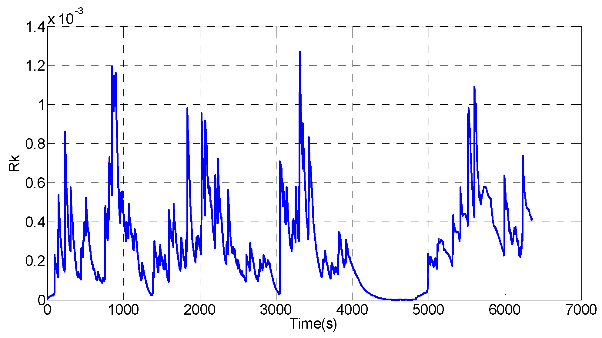
- Measurement update, which involves Kalman gain calculation, state estimation measurement update, and error covariance update:where , can be determined by the voltage sensors during operation, is the acquired measured voltage at step , and states a two-order unit matrix employed to update the error covariance.
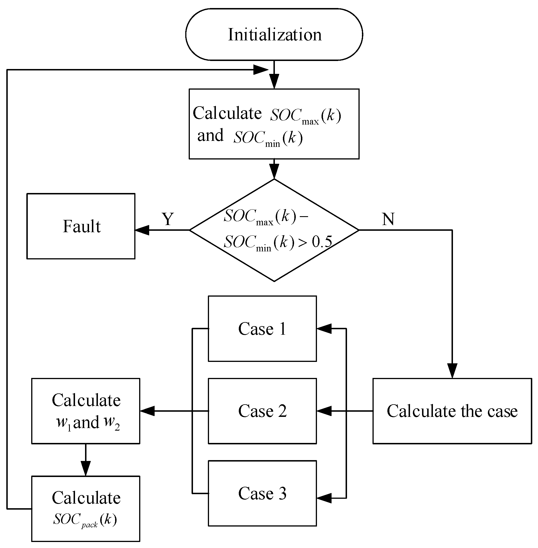
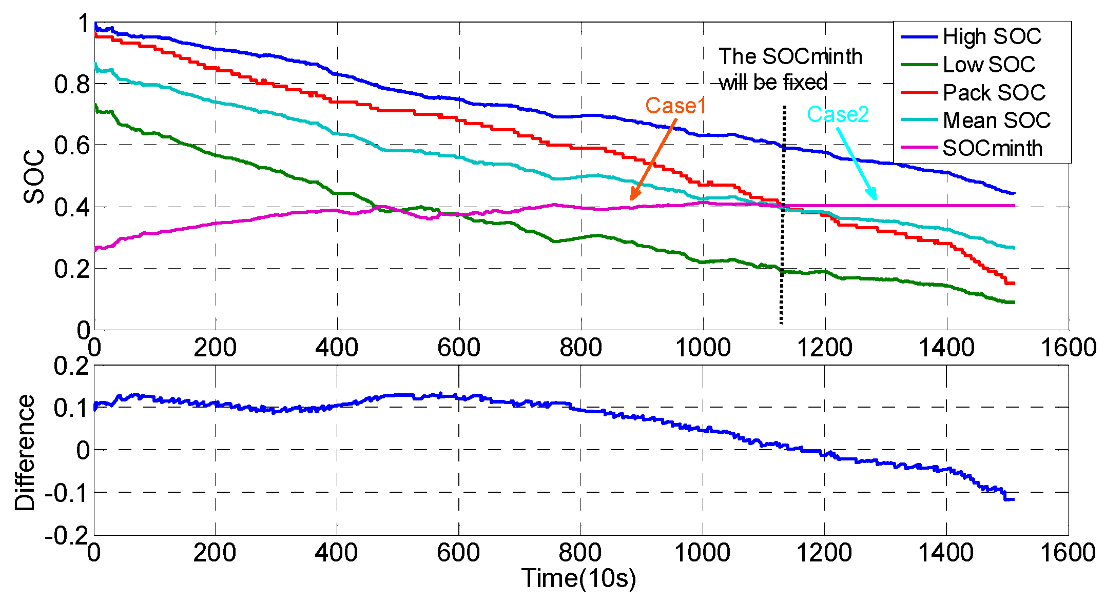
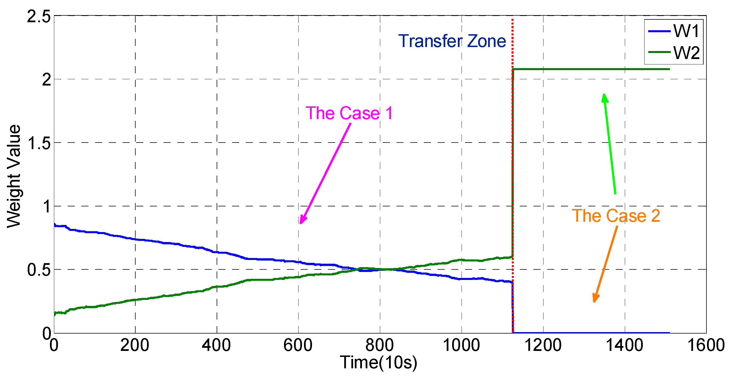
3.2. Battery Pack State of Charge Estimation
- (a)
- Case 1:Condition:Determination:
- (b)
- Case 2:Condition:Determination:
- (c)
- Case 3:Condition:Determination:
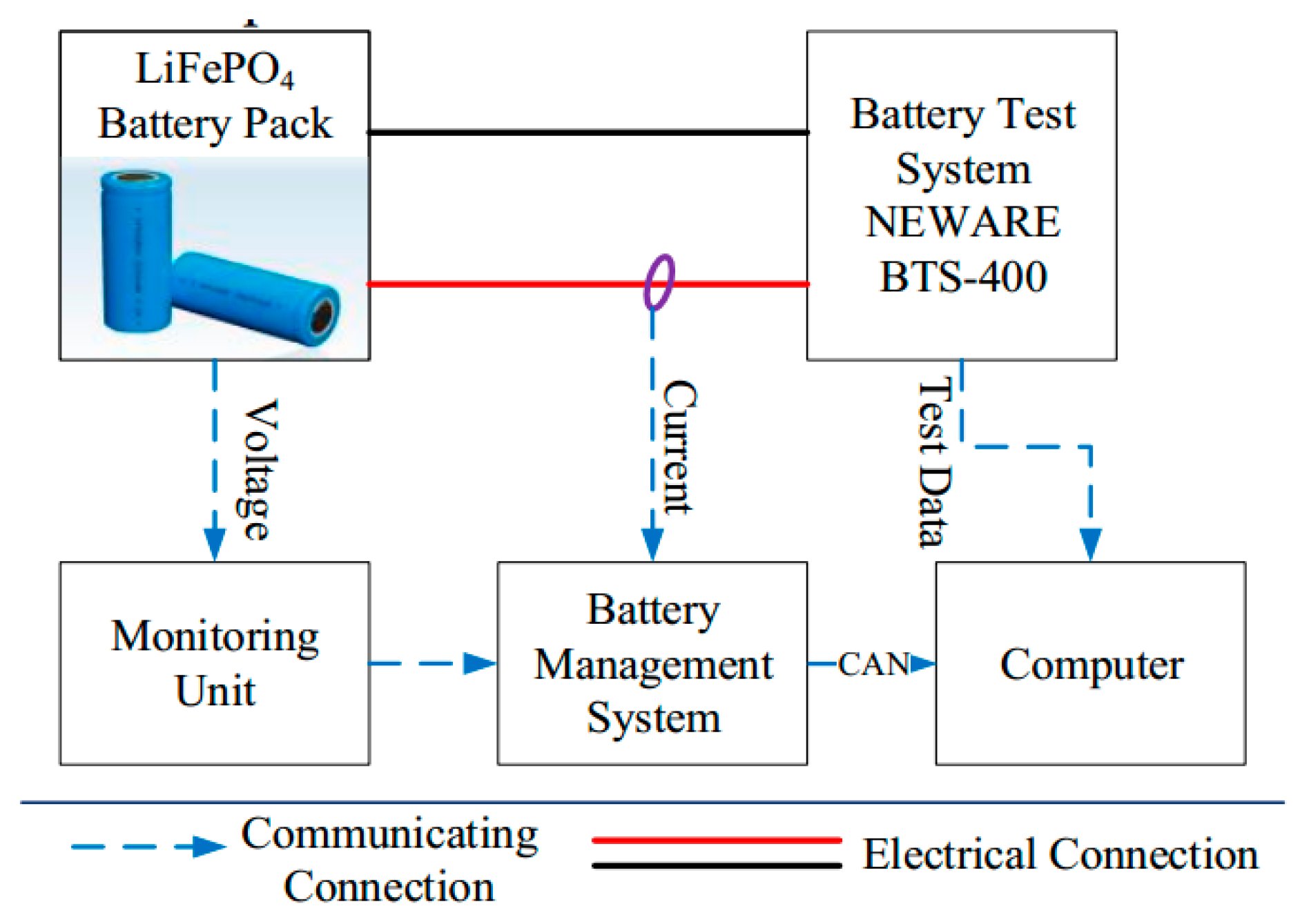
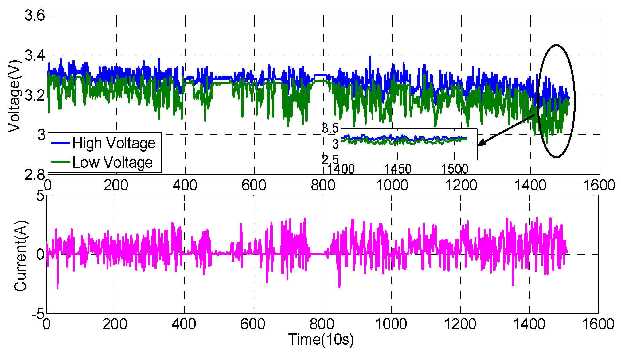
4. Experiment Validation
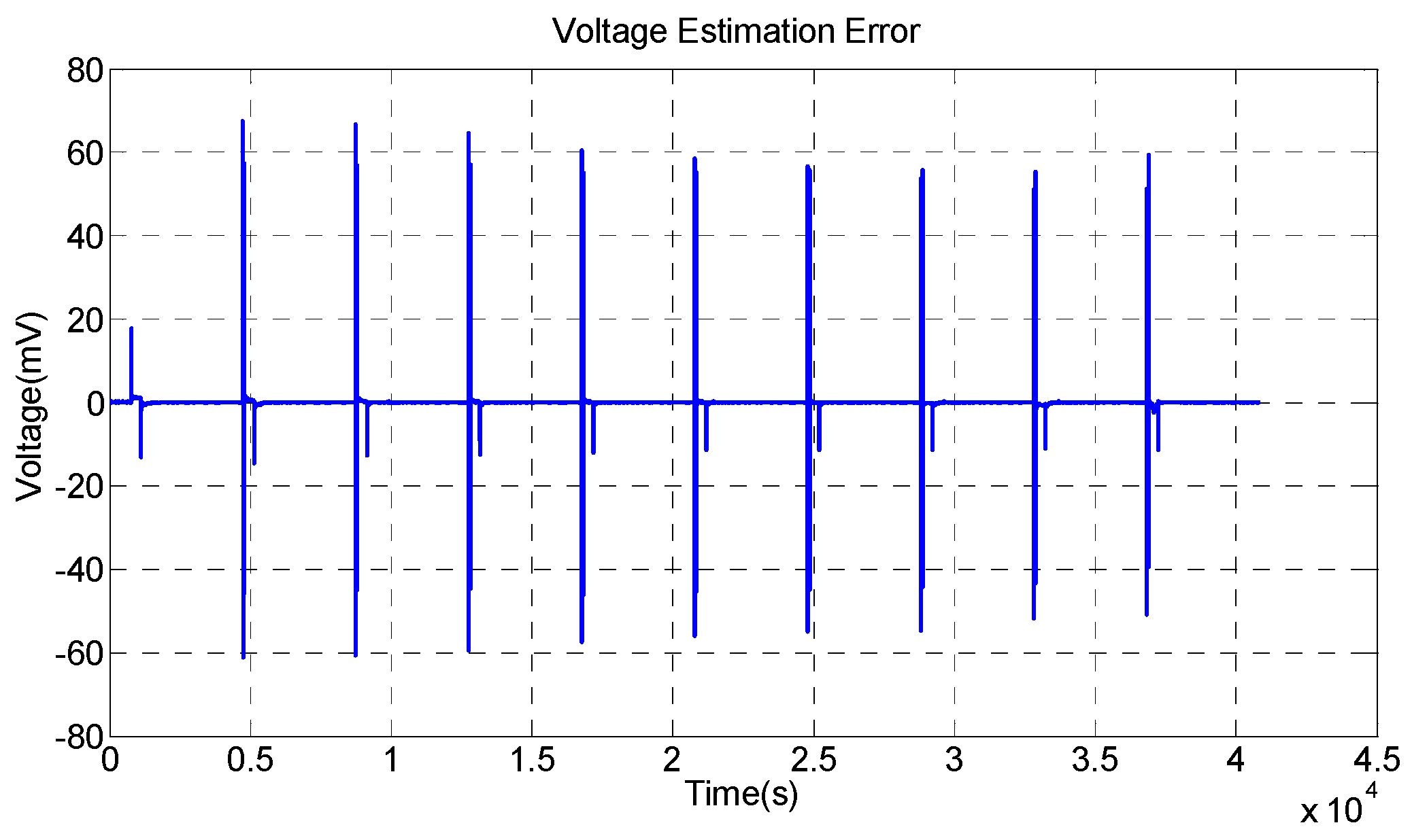
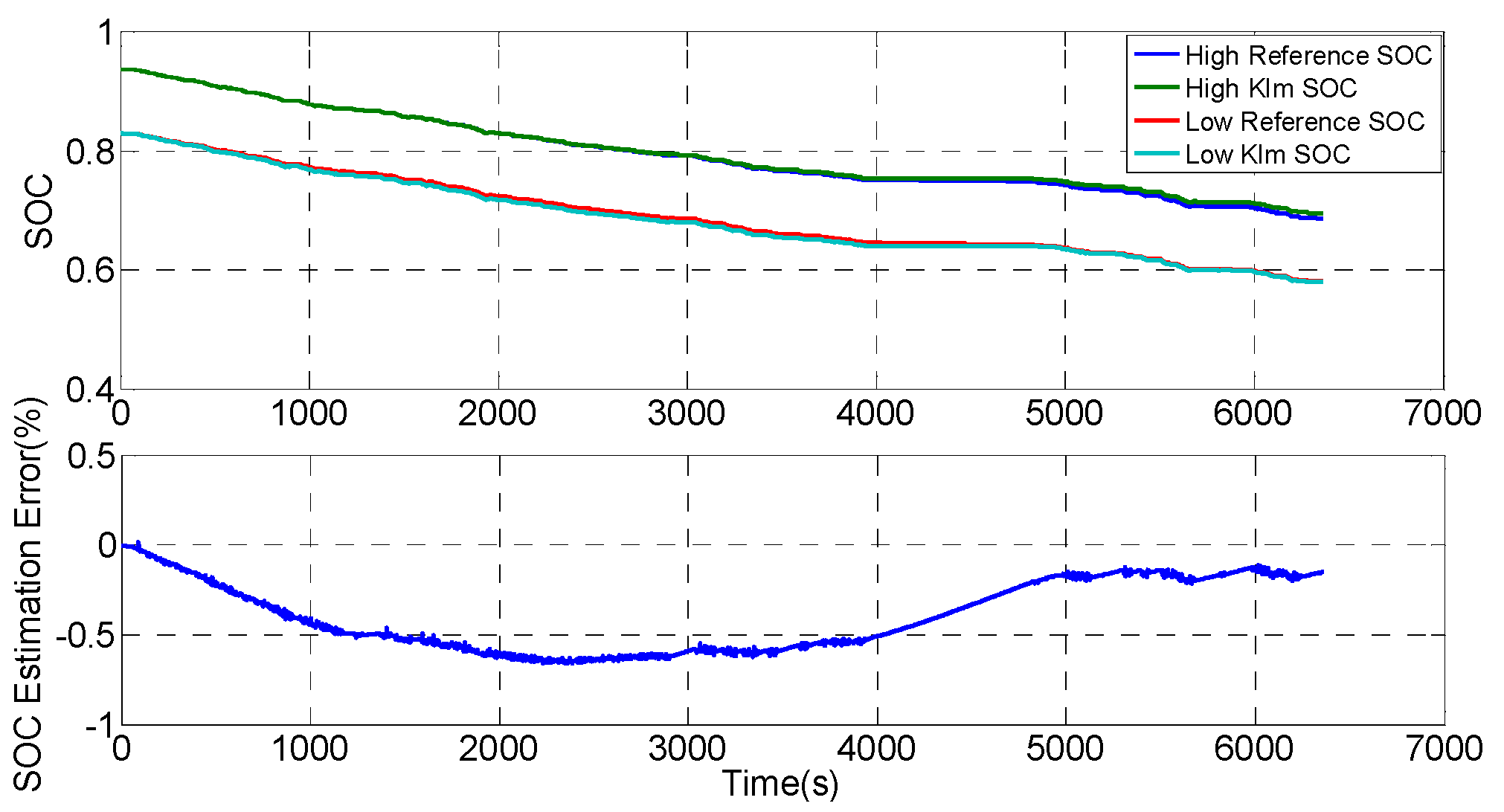
4.1. Laboratory Validation
4.2. Electric Vehicle Validation
5. Conclusions
Acknowledgments
Author Contributions
Conflicts of Interest
References
- Lawder, M.T.; Suthar, B.; Northrop, P.W.C.; De, S.; Hoff, C.M.; Leitermann, O. Battery Energy Storage System (BESS) and Battery Management System (BMS) for Grid-Scale Applications. Proc. IEEE 2014, 102, 1014–1030. [Google Scholar] [CrossRef]
- Lu, L.; Han, X.; Li, J.; Hua, J.; Ouyang, M. A review on the key issues for lithium-ion battery management in electric vehicles. J. Power Sources 2013, 226, 272–288. [Google Scholar] [CrossRef]
- Xiong, R.; Sun, F.; Chen, Z.; He, H. A data-driven multi-scale extended Kalman filtering based parameter and state estimation approach of lithium-ion polymer battery in electric vehicles. Appl. Energy 2014, 113, 463–476. [Google Scholar] [CrossRef]
- Zheng, Y.; Ouyang, M.; Lu, L.; Li, J.; Zhang, Z.; Li, X. Study on the correlation between state of charge and coulombic efficiency for commercial lithium ion batteries. J. Power Sources 2015, 289, 81–90. [Google Scholar] [CrossRef]
- Chen, Z.; Xia, B.; Mi, C.C. A novel state-of-charge estimation method for lithium-ion battery pack of electric vehicles. In Proceedings of the 2015 IEEE Transportation Electrification Conference and Expo (ITEC), Metro Detroit, MI, USA, 14–17 June 2015.
- Berecibar, M.; Gandiaga, I.; Villarreal, I.; Omar, N.; van Mierlo, J.; van den Bossche, P. Critical review of state of health estimation methods of Li-ion batteries for real applications. Renew. Sustain. Energy Rev. 2016, 56, 572–587. [Google Scholar] [CrossRef]
- Rahimi-Eichi, H.; Ojha, U.; Baronti, F.; Chow, M. Battery management system: An overview of its application in the smart grid and electric vehicles. IEEE Ind. Electron. Mag. 2013, 7, 4–16. [Google Scholar] [CrossRef]
- Dang, X.; Yan, L.; Xu, K.; Wu, X.; Jiang, H.; Sun, H. Open-circuit voltage-based state of charge estimation of lithium-ion battery using dual neural network fusion battery model. Electrochim. Acta 2016, 188, 356–366. [Google Scholar] [CrossRef]
- Dong, G.; Zhang, X.; Zhang, C.; Chen, Z. A method for state of energy estimation of lithium-ion batteries based on neural network model. Energy 2015, 90, 879–888. [Google Scholar] [CrossRef]
- Shen, Y. Adaptive online state-of-charge determination based on neuro-controller and neural network. Energy Convers. Manag. 2010, 51, 1093–1098. [Google Scholar] [CrossRef]
- Hu, J.N.; Hu, J.J.; Lin, H.B.; Li, X.P.; Jiang, C.L.; Qiu, X.H. State-of-charge estimation for battery management system using optimized support vector machine for regression. J. Power Sources 2014, 269, 682–693. [Google Scholar] [CrossRef]
- Patil, M.A.; Tagade, P.; Hariharan, K.S.; Kolake, S.M.; Song, T.; Yeo, T. A novel multistage support vector machine based approach for Li ion battery remaining useful life estimation. Appl. Energy 2015, 159, 285–297. [Google Scholar] [CrossRef]
- Sheng, H.; Xiao, J. Electric vehicle state of charge estimation: Nonlinear correlation and fuzzy support vector machine. J. Power Sources 2015, 281, 131–137. [Google Scholar] [CrossRef]
- Cai, C.H.; Du, D.; Liu, Z.Y. Battery state-of-charge (SOC) estimation using adaptive neuro-fuzzy inference system (ANFIS). In Proceedings of the 12th IEEE International Conference on Fuzzy Systems (FUZZ’03), St. Louis, MO, USA, 25–28 May 2003; pp. 1068–1073.
- Dai, H.; Guo, P.; Wei, X.; Sun, Z.; Wang, J. ANFIS (adaptive neuro-fuzzy inference system) based online SOC (State of Charge) correction considering cell divergence for the EV (electric vehicle) traction batteries. Energy 2015, 80, 350–360. [Google Scholar] [CrossRef]
- Zheng, Y.; Ouyang, M.; Lu, L.; Li, J.; Han, X.; Xu, L. On-line equalization for lithium-ion battery packs based on charging cell voltages: Part 2. Fuzzy logic equalization. J. Power Sources 2014, 247, 460–466. [Google Scholar] [CrossRef]
- He, W.; Williard, N.; Chen, C.; Pecht, M. State of charge estimation for Li-ion batteries using neural network modeling and unscented Kalman filter-based error cancellation. Int. J. Electr. Power Energy Syst. 2014, 62, 783–791. [Google Scholar] [CrossRef]
- Kang, L.; Zhao, X.; Ma, J. A new neural network model for the state-of-charge estimation in the battery degradation process. Appl. Energy 2014, 121, 20–27. [Google Scholar] [CrossRef]
- Sakthivel, R.; Anbuvithya, R.; Mathiyalagan, K.; Prakash, P. Combined H∞ and passivity state estimation of memristive neural networks with random gain fluctuations. Neurocomputing 2015, 168, 1111–1120. [Google Scholar] [CrossRef]
- He, Y.; Liu, X.; Zhang, C.; Chen, Z. A new model for State-of-Charge (SOC) estimation for high-power Li-ion batteries. Appl. Energy 2013, 101, 808–814. [Google Scholar] [CrossRef]
- Weigert, T.; Tian, Q.; Lian, K. State-of-charge prediction of batteries and battery-supercapacitor hybrids using artificial neural networks. J. Power Sources 2011, 196, 4061–4066. [Google Scholar] [CrossRef]
- Xu, L.; Wang, J.; Chen, Q. Kalman filtering state of charge estimation for battery management system based on a stochastic fuzzy neural network battery model. Energy Convers. Manag. 2012, 53, 33–39. [Google Scholar] [CrossRef]
- Wang, Y.; Zhang, C.; Chen, Z. On-line battery state-of-charge estimation based on an integrated estimator. Appl. Energy 2015. [Google Scholar] [CrossRef]
- Plett, G.L. Extended Kalman filtering for battery management systems of LiPB-based HEV battery packs: Part 3. State and parameter estimation. J. Power Sources 2004, 134, 277–292. [Google Scholar] [CrossRef]
- Xiao, R.; Shen, J.; Li, X.; Yan, W.; Pan, E.; Chen, Z. Comparisons of modeling and state of charge estimation for lithium-ion battery based on fractional order and integral order methods. Energies 2016, 9, 184. [Google Scholar] [CrossRef]
- Plett, G.L. Sigma-point Kalman filtering for battery management systems of LiPB-based HEV battery packs: Part 1: Introduction and state estimation. J. Power Sources 2006, 161, 1356–1368. [Google Scholar] [CrossRef]
- He, W.; Williard, N.; Chen, C.; Pecht, M. State of charge estimation for electric vehicle batteries using unscented kalman filtering. Microelectron. Reliab. 2013, 53, 840–847. [Google Scholar] [CrossRef]
- Han, J.; Kim, D.; Sunwoo, M. State-of-charge estimation of lead-acid batteries using an adaptive extended Kalman filter. J. Power Sources 2009, 188, 606–612. [Google Scholar] [CrossRef]
- Xiong, R.; He, H.; Sun, F.; Zhao, K. Evaluation on state of charge estimation of batteries with adaptive extended Kalman filter by experiment approach. IEEE Trans. Veh. Technol. 2013, 62, 108–117. [Google Scholar] [CrossRef]
- Zhong, L.; Zhang, C.; He, Y.; Chen, Z. A method for the estimation of the battery pack state of charge based on in-pack cells uniformity analysis. Appl. Energy 2014, 113, 558–564. [Google Scholar] [CrossRef]
- Sun, F.; Xiong, R. A novel dual-scale cell state-of-charge estimation approach for series-connected battery pack used in electric vehicles. J. Power Sources 2015, 274, 582–594. [Google Scholar] [CrossRef]
- Sun, F.; Xiong, R.; He, H. A systematic state-of-charge estimation framework for multi-cell battery pack in electric vehicles using bias correction technique. Appl. Energy 2016, 162, 1399–1409. [Google Scholar] [CrossRef]
- Cuadras, A.; Kanoun, O. SOC Li-ion battery monitoring with impedance spectroscopy. In Proceedings of the 6th International Multi-Conference on Systems, Signals and Devices (SSD ’09), Djerba, Tunisia, 23–26 March 2009.
- Domenico, D.D.; Fiengo, G.; Stefanopoulou, A. Lithium-ion battery state of charge estimation with a Kalman Filter based on an electrochemical model. In Proceedings of the IEEE International Conference on Control Applications (CCA 2008), San Antonio, TX, USA, 3–5 September 2008; pp. 702–707.
- Lee, S.; Kim, J.; Lee, J.; Cho, B.H. State-of-charge and capacity estimation of lithium-ion battery using a new open-circuit voltage versus state-of-charge. J. Power Sources 2008, 185, 1367–1373. [Google Scholar] [CrossRef]
- Sun, D.; Chen, X. Adaptive parameter identification method and state of charge estimation of Lithium ion battery. In Proceedings of the 17th IEEE International Conference on Electrical Machines and Systems (ICEMS), Hangzhou, China, 22–25 October 2014; pp. 855–860.
- Andre, D.; Appel, C.; Soczka-Guth, T.; Sauer, D.U. Advanced mathematical methods of SOC and SOH estimation for lithium-ion batteries. J. Power Sources 2013, 224, 20–27. [Google Scholar] [CrossRef]
- Tong, S.; Klein, M.P.; Park, J.W. On-line optimization of battery open circuit voltage for improved state-of-charge and state-of-health estimation. J. Power Sources 2015, 293, 416–428. [Google Scholar] [CrossRef]
- Chen, Z.; Mi, C.C.; Fu, Y.; Xu, J.; Gong, X. Online battery state of health estimation based on Genetic Algorithm for electric and hybrid vehicle applications. J. Power Sources 2013, 240, 184–192. [Google Scholar] [CrossRef]
- Chen, Z.; Fu, Y.; Mi, C.C. State of charge estimation of lithium-ion batteries in electric drive vehicles using extended Kalman filtering. IEEE Trans. Veh. Technol. 2013, 62, 1020–1030. [Google Scholar] [CrossRef]
- Chen, Z.; Mi, C.C.; Xiong, R.; Xu, J.; You, C. Energy management of a power-split plug-in hybrid electric vehicle based on genetic algorithm and quadratic programming. J. Power Sources 2014, 248, 416–426. [Google Scholar] [CrossRef]
- Yang, X.S. Genetic Algorithms. In Nature-Inspired Optimization Algorithms; Elsevier: Oxford, UK, 2014; Chapter 5; pp. 77–87. [Google Scholar]


© 2016 by the authors; licensee MDPI, Basel, Switzerland. This article is an open access article distributed under the terms and conditions of the Creative Commons Attribution (CC-BY) license (http://creativecommons.org/licenses/by/4.0/).
Share and Cite
Chen, Z.; Li, X.; Shen, J.; Yan, W.; Xiao, R. A Novel State of Charge Estimation Algorithm for Lithium-Ion Battery Packs of Electric Vehicles. Energies 2016, 9, 710. https://doi.org/10.3390/en9090710
Chen Z, Li X, Shen J, Yan W, Xiao R. A Novel State of Charge Estimation Algorithm for Lithium-Ion Battery Packs of Electric Vehicles. Energies. 2016; 9(9):710. https://doi.org/10.3390/en9090710
Chicago/Turabian StyleChen, Zheng, Xiaoyu Li, Jiangwei Shen, Wensheng Yan, and Renxin Xiao. 2016. "A Novel State of Charge Estimation Algorithm for Lithium-Ion Battery Packs of Electric Vehicles" Energies 9, no. 9: 710. https://doi.org/10.3390/en9090710
APA StyleChen, Z., Li, X., Shen, J., Yan, W., & Xiao, R. (2016). A Novel State of Charge Estimation Algorithm for Lithium-Ion Battery Packs of Electric Vehicles. Energies, 9(9), 710. https://doi.org/10.3390/en9090710