
Heat Transfer and Energy Performance of a PVA Wall Tile Containing Macro-Encapsulated PCM


Abstract
:
1. Introduction
2. Research Method
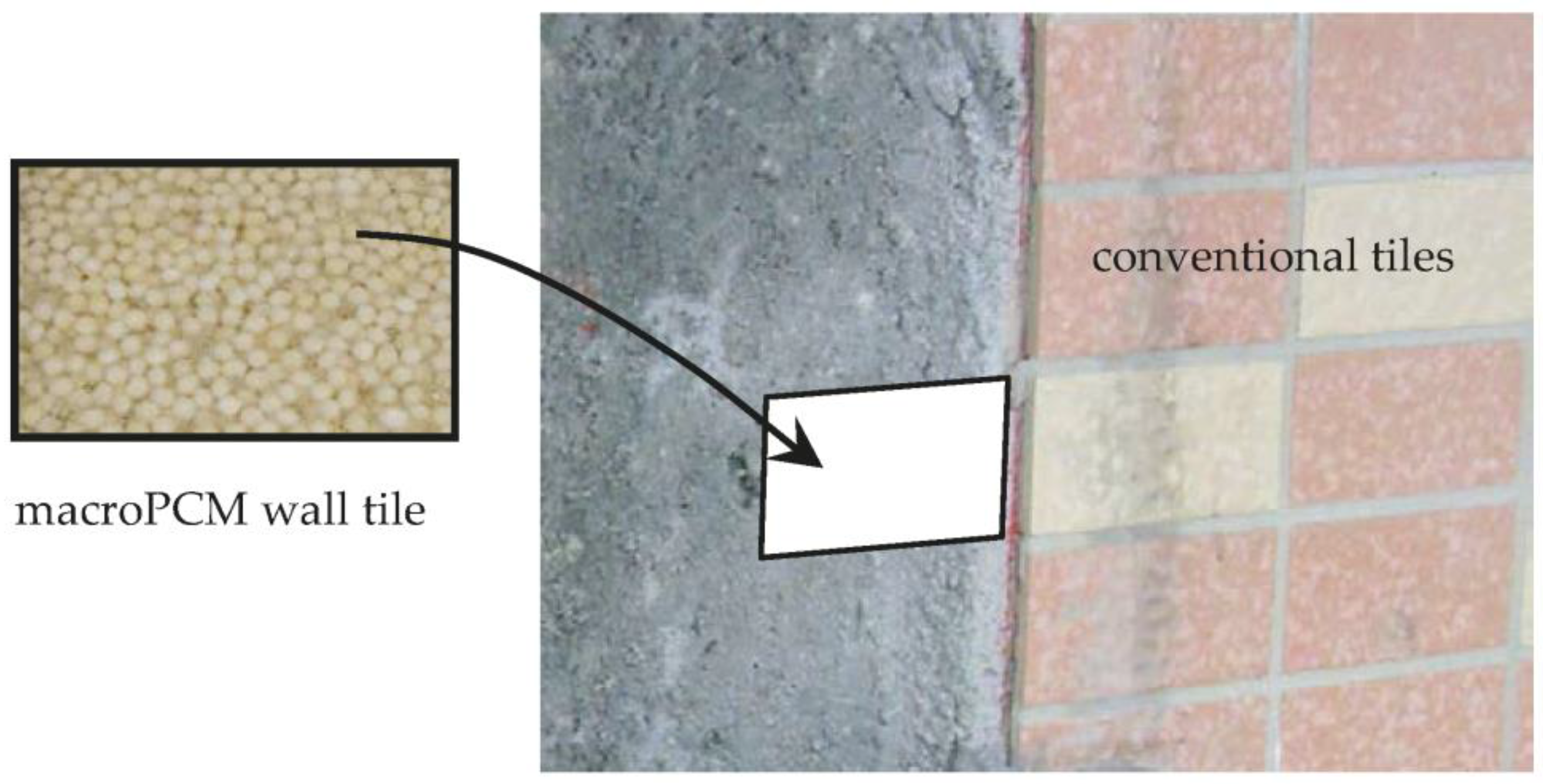
2.1. Practice Consideration
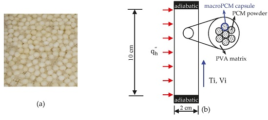
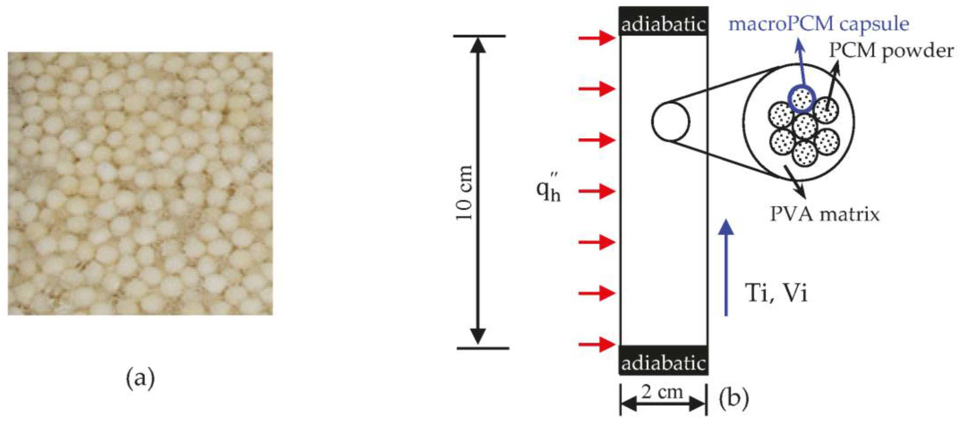
2.2. Experimental Test Cell
- (1)
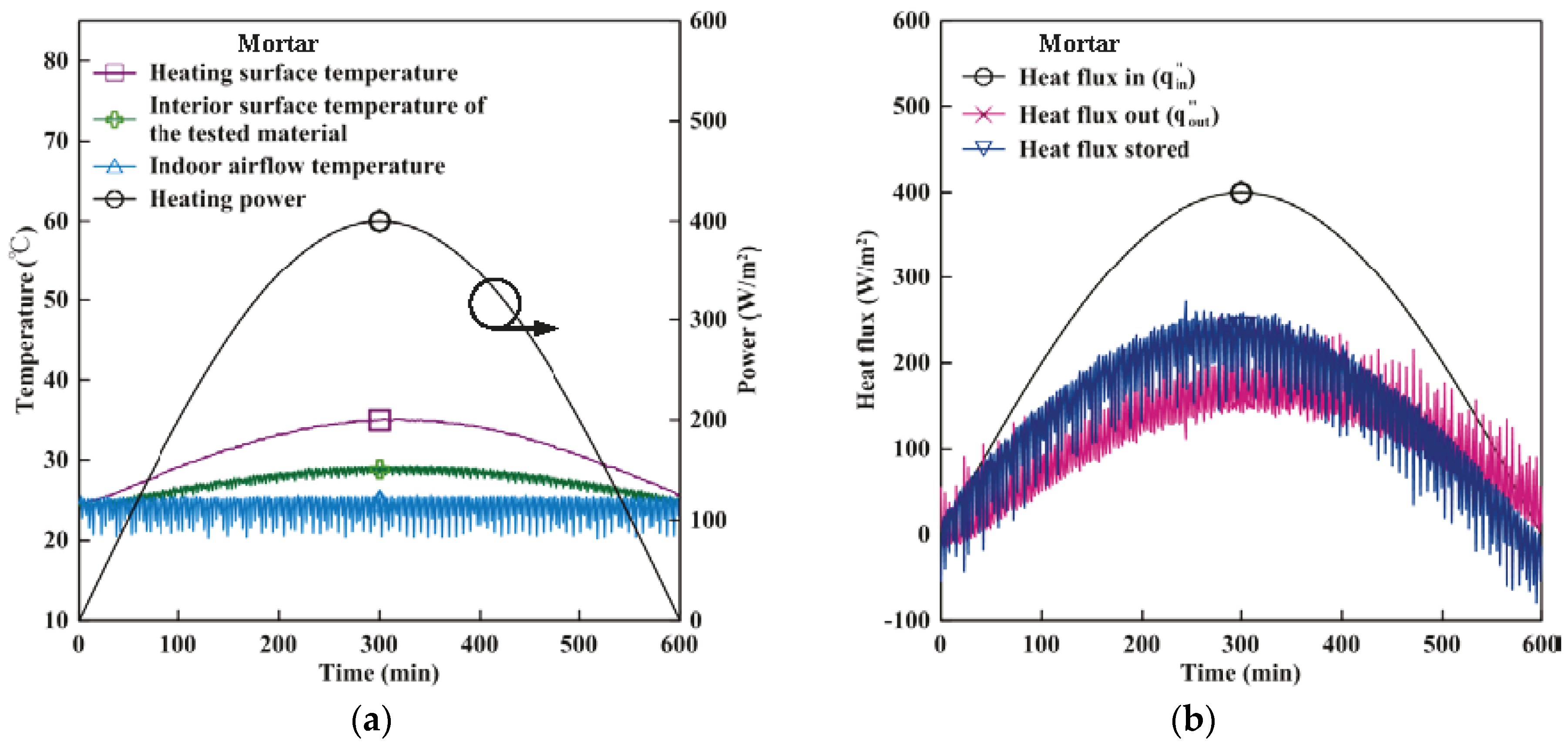
- Cement mortar was filled in a balsa board box to form an investigation target (hereafter, mortar).
- (2)
- Both macroPCM (67.75 g) and cement mortar were tightly packed in a balsa board box to obtain an investigation target (hereafter, macroPCM + mortar).
- (3)
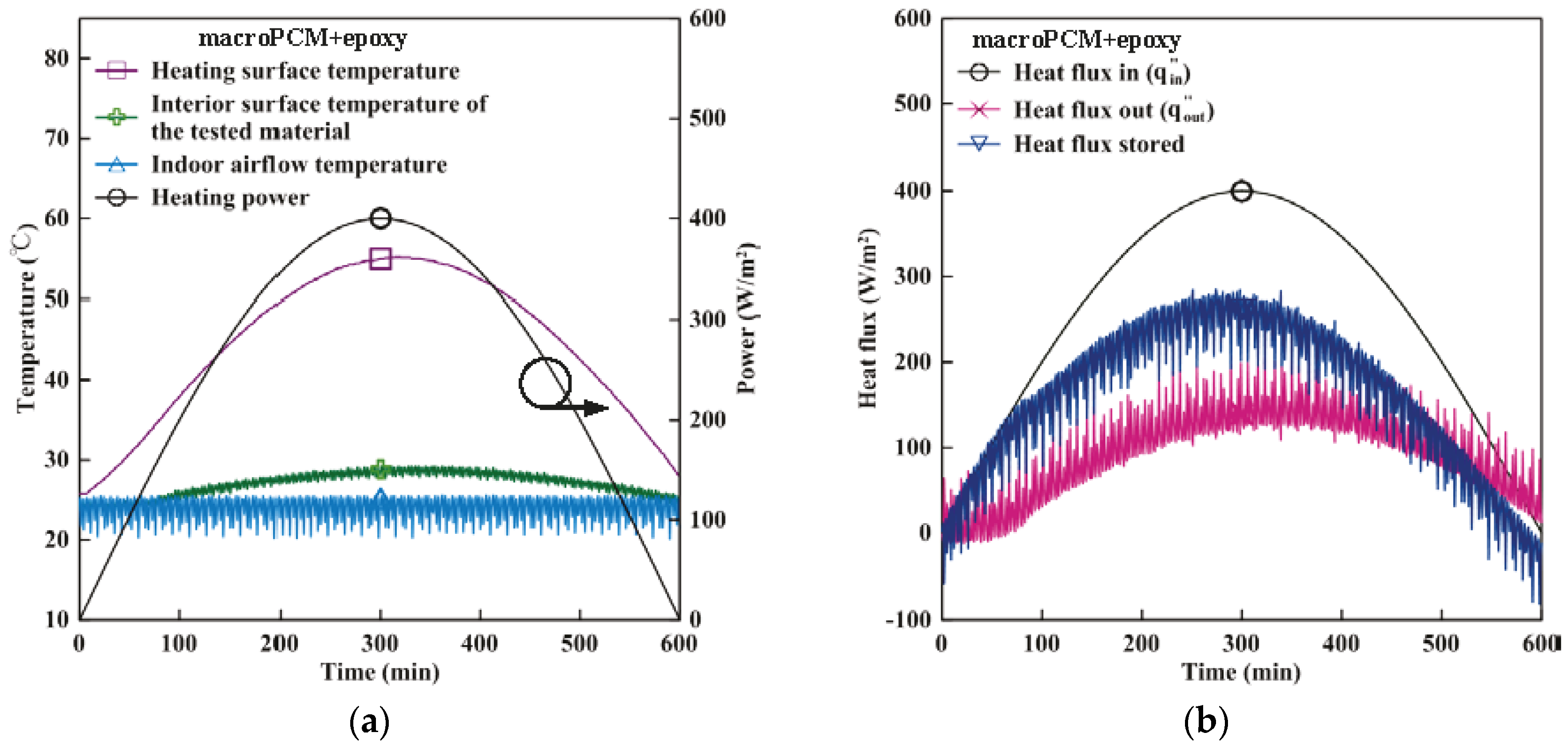
- Both macro PCM and commercially available epoxy were filled into a balsa board box to obtain an investigation target (hereafter, macroPCM + epoxy). The masses of the materials used are 68.6 g for epoxy and 89.6 g for macro PCM (i.e., 56.6% of the investigation target).
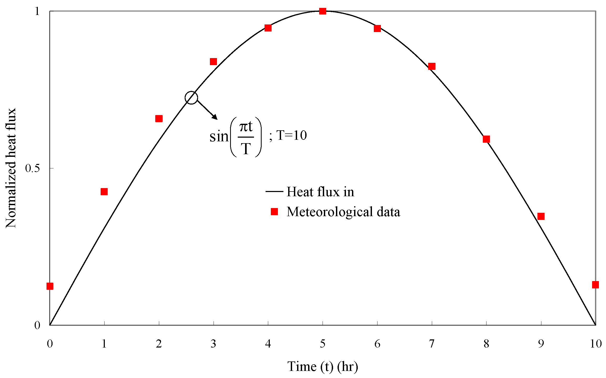
2.2.1. Hot Wall with Time-Variant Heat Flux,
2.2.2. Cold Wall with Convective Heat Transfer Conditions
2.2.3. Temperature and Heat Flow Measurement
2.3. The MacroPCM Capsule Employed
2.4. Experiment Steps
2.5. Data Analysis
- (1)
- Input power,Voltage V (V) and electric current I (A) values from the power supply unit were acquired with the data acquisition unit. From these values, the input power could be determined as (W), .
- (2)
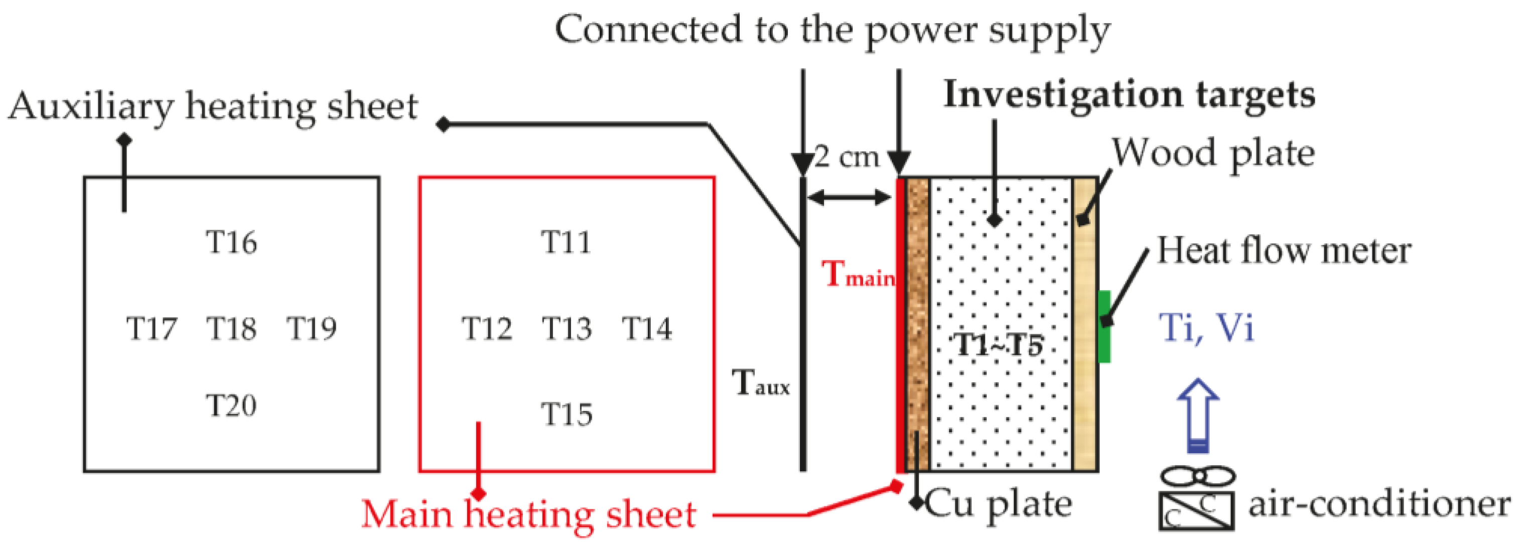
- Heat loss estimation,It was difficult to maintain the auxiliary heating sheet temperature matched to the main heating sheet temperature. The heat transfer between the main and auxiliary heating sheets had to be considered. The distance from the main heating sheet to the auxiliary heating sheet was 2 cm. The heat transfer between the main and auxiliary heating sheets was divided into two conditions:
- (a)
- , Equation (2) applied:
- (b)
Rayleigh numbers () were calculated using Equation (5):where (W/m·K) is the thermal conductivity of air, (K) is the surface temperature of the main heating sheet, (K) is the surface temperature of the auxiliary heating sheet, A is the area of heat transfer (10 × 10 cm), Ws is the distance between the main and auxiliary heating sheets (2 cm), and are the respective surface emissivity (0.074) of the two heating sheets, is the Stefan–Boltzmann constant (5.67 × 10⁻⁸ W/m2K4), (1/K) is the thermal expansion coefficient of air, Pr is the Prandtl number of air, (K) is the temperature difference between the main and auxiliary heating sheets, (m2/s) is the thermal diffusion coefficient of air, and (m2/s) is the kinematic viscosity of air. - (3)
- Modified input heat,After heat loss was calculated, (W) was subtracted from (W) to obtain the modified input heat, (W). was positive when the auxiliary heating sheet temperature was lower than that of the main heating sheet, whereas it was negative when the auxiliary heating sheet temperature was higher than the main heating sheet temperature.
- (4)
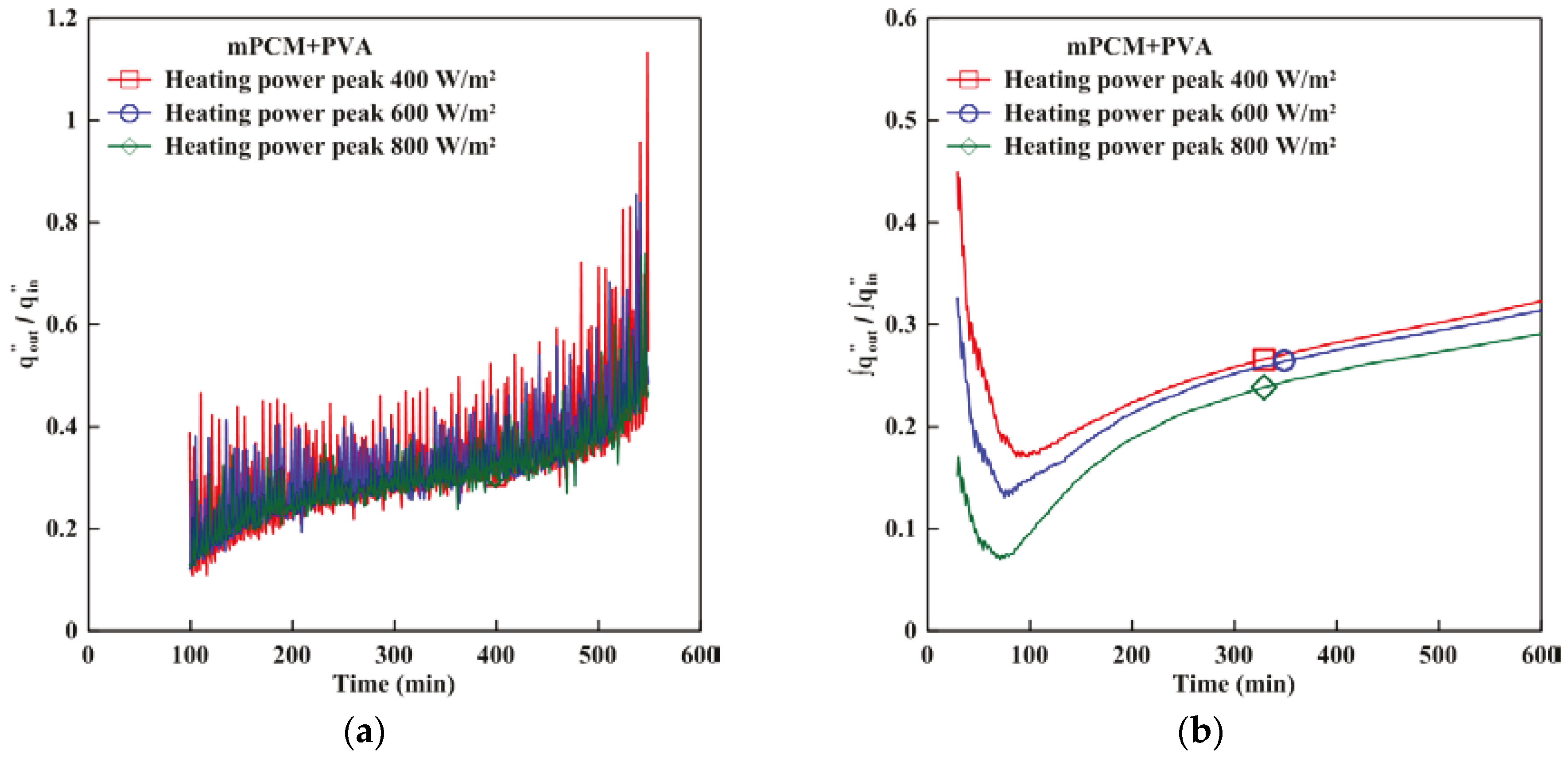
- Instantaneous fractional heat penetration, Qr,iwhere and are the time-variant heat fluxes (W/m2) at the hot and cold walls, respectively.
- (5)
- Time-averaged fractional heat penetration, Qr,t
2.6. Experimental Uncertainty
3. Results and Discussion
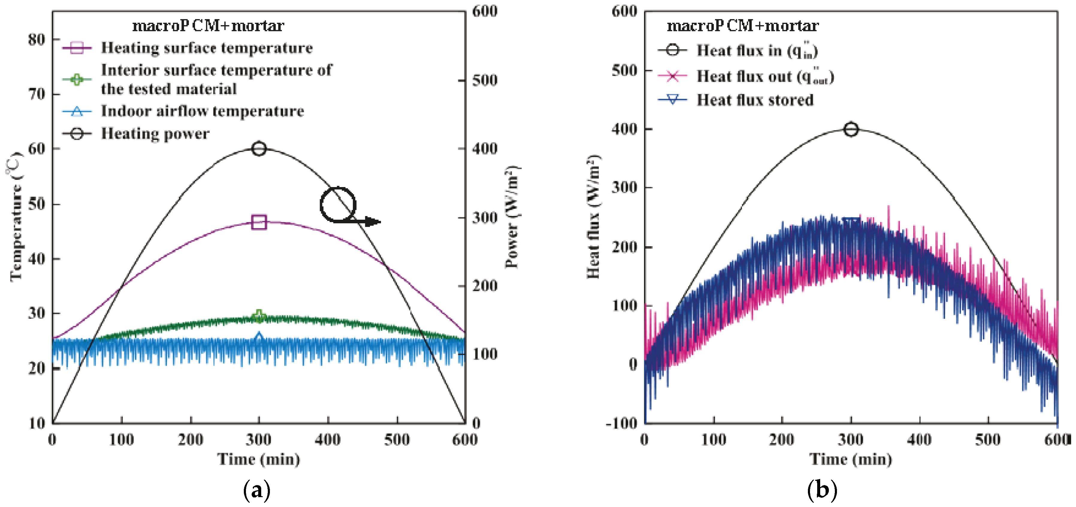
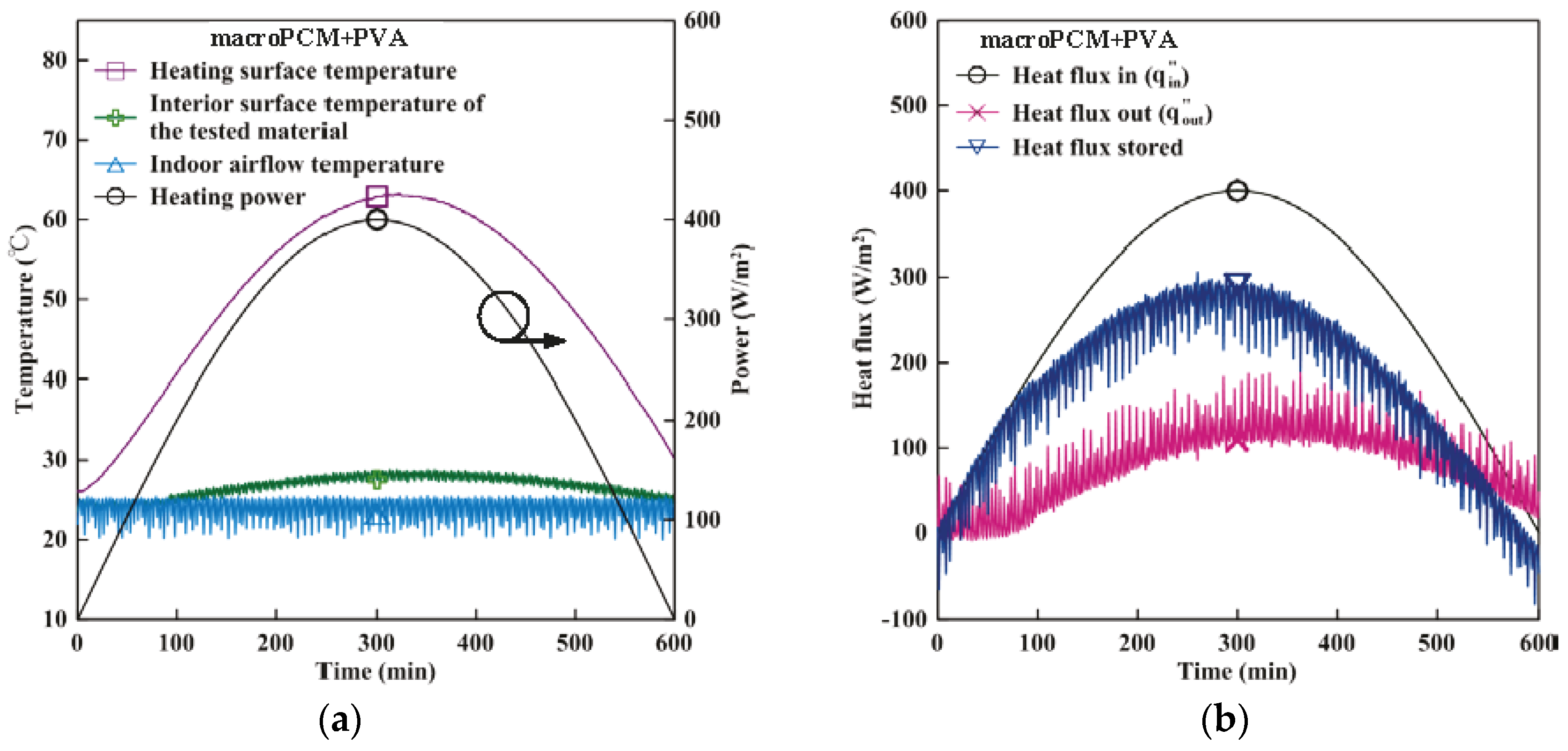
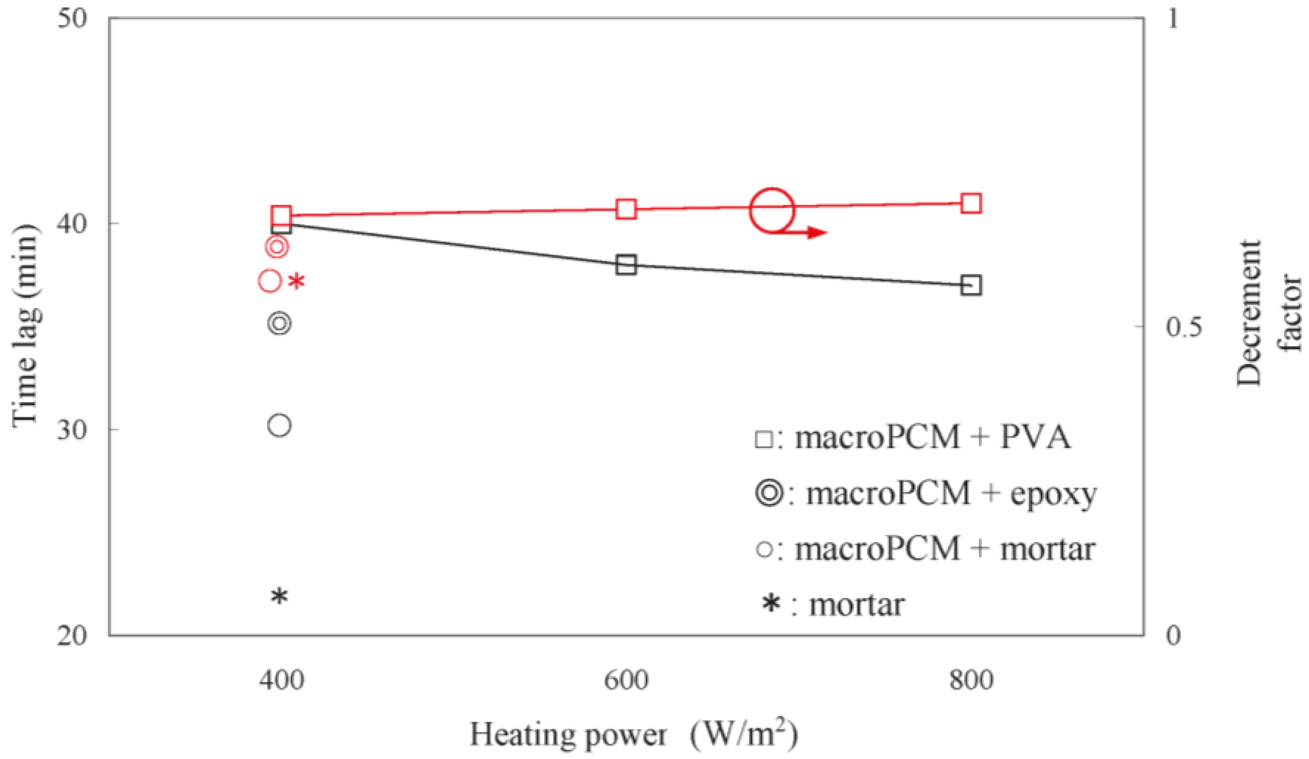
3.1. Heat Transfer Analysis of the Investigated Targets
3.2. Dimensionless Heat Transfer Analysis of the MacroPCM + PVA Wall Tile
4. Conclusions
Acknowledgments
Author Contributions
Conflicts of Interest
References
- Zuo, J.; Li, W.; Weng, L. Thermal performance of caprylic acid/1-dodecanol eutectic mixture as phase change material (PCM). Energy Build. 2011, 43, 207–210. [Google Scholar] [CrossRef]
- Wu, S.; Fang, G. Dynamic performances of solar heat storage system with packed bed using myristic acid as phase change material. Energy Build. 2011, 43, 1091–1096. [Google Scholar] [CrossRef]
- Jaber, S.; Ajib, S. Novel cooling unit using PCM for residential application. Int. J. Refrig. 2012, 35, 1292–1303. [Google Scholar] [CrossRef]
- Mandilaras, I.; Stamatiadou, M.; Katsourinis, D.; Zannis, G.; Founti, M. Experimental thermal characterization of a Mediterranean residential building with PCM gypsum board walls. Build. Environ. 2013, 61, 93–103. [Google Scholar] [CrossRef]
- Lai, C.M.; Chen, R.H.; Lin, C.Y. Heat transfer and thermal storage behavior of gypsum boards incorporating micro-encapsulated PCM. Energy Build. 2010, 42, 1259–1266. [Google Scholar] [CrossRef]
- David, D.; Kuznik, F.; Roux, J.J. Numerical study of the influence of the convective heat transfer on the dynamical behavior of a phase change material wall. Appl. Therm. Eng. 2011, 31, 3117–3124. [Google Scholar] [CrossRef]
- Izquierdo-Barrientos, M.A.; Belmonte, J.F.; Rodríguez-Sánchez, D.; Molina, A.E.; Almendros-Ibáñez, J.A. A numerical study of external building walls containing phase change materials (PCM). Appl. Therm. Eng. 2012, 47, 73–85. [Google Scholar] [CrossRef]
- Delgado, M.; Lázaro, A.; Mazo, J.; Marín, J.M.; Zalba, B. Experimental analysis of a microencapsulated PCM slurry as thermal storage system and as heat transfer fluid in laminar flow. Appl. Therm. Eng. 2012, 36, 370–377. [Google Scholar] [CrossRef]
- Soares, N.; Costa, J.J.; Gaspar, A.R.; Santos, P. Review of passive PCM latent heat thermal energy storage systems towards buildings’ energy efficiency. Energy Build. 2013, 59, 82–103. [Google Scholar] [CrossRef]
- Osterman, E.; Tyagi, V.V.; Butala, V.; Rahim, N.A.; Stritih, U. Review of PCM based cooling technologies for buildings. Energy Build. 2012, 49, 37–49. [Google Scholar] [CrossRef]
- Salunkhe, P.B.; Shembekar, P.S. A review on effect of phase change material encapsulation on the thermal performance of a system. Renew. Sustain. Energy Rev. 2012, 16, 5603–5616. [Google Scholar] [CrossRef]
- Hasse, C.; Grenet, M.; Bontemps, A.; Dendievel, R.; Sallee, H. Realization, test and modelling of honeycomb wallboards containing a Phase Change Material. Energy Build. 2011, 43, 232–238. [Google Scholar] [CrossRef]
- Mahmoud, S.; Tang, A.; Toh, C.; AL-Dadah, R.; Soo, S.L. Experimental investigation of inserts configurations and PCM type on the thermal performance of PCM based heat sinks. Appl. Energy 2013, 112, 1349–1356. [Google Scholar] [CrossRef]
- Schossig, P.; Henning, H.M.; Gschwander, S.; Haussmann, T. Micro-encapsulated phase-change materials integrated into construction materials. Sol. Energy Mater. Sol. Cells 2005, 89, 297–306. [Google Scholar] [CrossRef]
- Lai, C.M.; Hokoi, S. Thermal performance of an aluminum honeycomb wallboard incorporating microencapsulated PCM. Energy Build. 2014, 73, 37–47. [Google Scholar] [CrossRef]
- Incropera, F.P.; DeWitt, D.P.; Bergman, T.L.; Lavines, A.S. Principles of Heat and Mass Transfer, 7th ed.; John Wiley & Sons: Hoboken, NJ, USA, 2013. [Google Scholar]


© 2016 by the authors; licensee MDPI, Basel, Switzerland. This article is an open access article distributed under the terms and conditions of the Creative Commons Attribution (CC-BY) license (http://creativecommons.org/licenses/by/4.0/).
Share and Cite
Liu, P.-F.; Lin, Y.-P.; Tzeng, C.-T.; Lai, C.-M. Heat Transfer and Energy Performance of a PVA Wall Tile Containing Macro-Encapsulated PCM. Energies 2016, 9, 652. https://doi.org/10.3390/en9080652
Liu P-F, Lin Y-P, Tzeng C-T, Lai C-M. Heat Transfer and Energy Performance of a PVA Wall Tile Containing Macro-Encapsulated PCM. Energies. 2016; 9(8):652. https://doi.org/10.3390/en9080652
Chicago/Turabian StyleLiu, Pin-Feng, Yi-Pin Lin, Chun-Ta Tzeng, and Chi-Ming Lai. 2016. "Heat Transfer and Energy Performance of a PVA Wall Tile Containing Macro-Encapsulated PCM" Energies 9, no. 8: 652. https://doi.org/10.3390/en9080652
APA StyleLiu, P.-F., Lin, Y.-P., Tzeng, C.-T., & Lai, C.-M. (2016). Heat Transfer and Energy Performance of a PVA Wall Tile Containing Macro-Encapsulated PCM. Energies, 9(8), 652. https://doi.org/10.3390/en9080652