1. Introduction
With the emergence of an energy crisis, ways of reducing air-pollution have become the great challenge [
1]. Electric vehicles (EVs) contribute significantly to energy saving and environmental protection, and on account of these benefits, they constitute today’s direction for the automotive industry [
2]. A compact and highly-reliable electric traction motor, which has high efficiency over a wide speed range with load-adaptive controllable speed-torque contours, is crucial for any electric propulsion system [
3,
4]. Traction motors of EVs should have high torque density in terms of weight and volume, a wide range of torque-speed characteristics, high operating efficiency, and high reliability. The novel structure of a brushless, doubly-fed generator (BDFG) proposed in [
5], which has the aforementioned advantages, can be efficiently applied to EVs. To distinguish the different applications of such machines, the concept of dual-stator flux-modulated (DSFM) motors for EVs was presented.
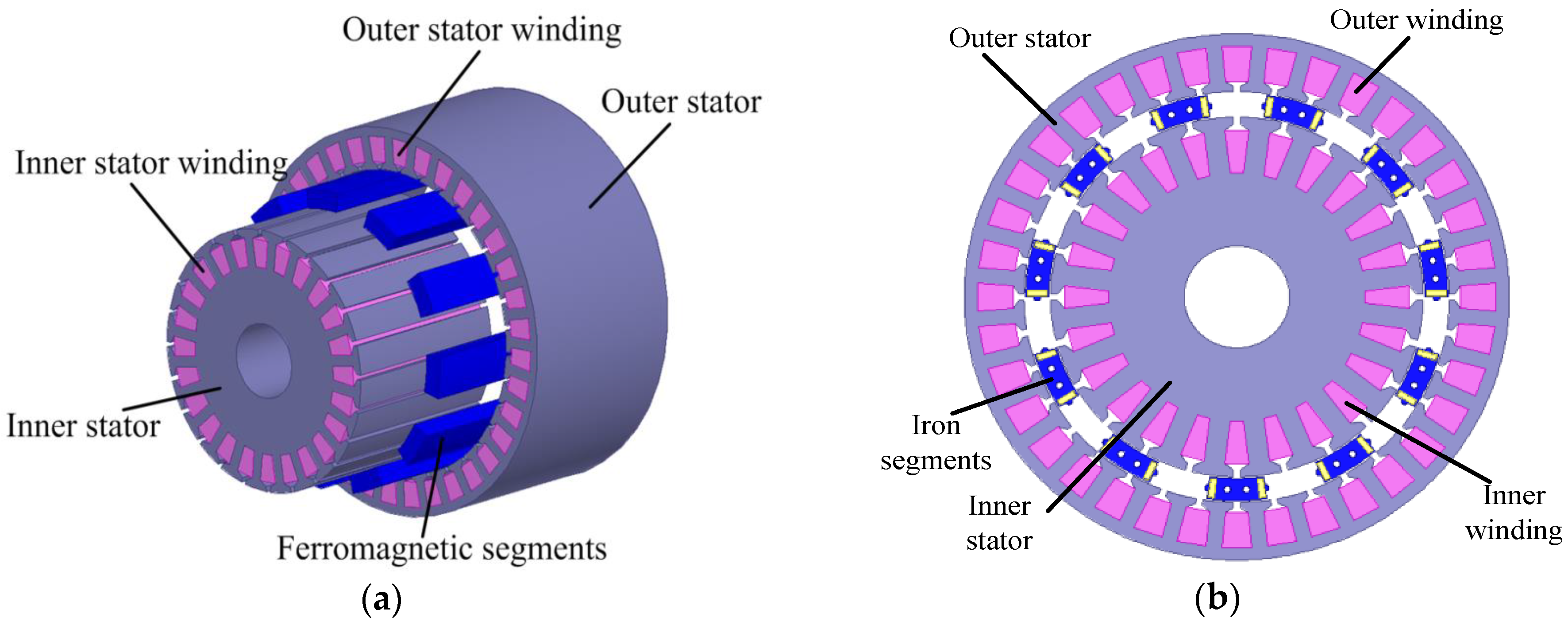
Figure 1 illustrates a novel machine, which has a three-phase, 36-slot, 12-pole winding on the outer stator and three-phase, 24-slot, 10-pole winding on the inner stator. Compared with most permanent magnet synchronous motors (PMSMs), the DSFM motor with a wide range of speeds and torques and no flux-weakening control yields higher performance in EVs [
5].
Conventional brushless, doubly-fed machines (BDFMs), such as BDFG, have been designed and investigated only for wind energy systems [
6,
7,
8,
9,
10]. In particular, control strategies for BDFMs, such as direct torque and flux control [
11], voltage vector-oriented control (VC) [
12,
13], and field-oriented control (FOC) [
14,
15], have been investigated. The FOC and VC schemes were compared in [
15] and the advantages and disadvantages of the two control methods were presented. The structural diagram of the brushless, doubly-fed reluctance machine (BDFRM (G)) drive setup is depicted in
Figure 2 [
13].
However, the application of the flux-modulated motor to EVs has not been fully investigated, especially the control strategies. In this paper, the air gap structures of the DSFM motor and BDFRM were compared and dynamic models were investigated, and the operating principle of this motor was verified through the open-loop variable voltage and variable frequency (VVVF) control. Moreover, two closed loop control methods, stator-current-oriented vector control (SCOVC) with direct current (DC) excitation and alternating current (AC) excitation, were proposed to ensure that the motor operates at different speeds and load conditions. Simulation and experiment results obtained for a customised prototype completely validated the feasibility of the two control strategies.
2. Dynamic Modelling of Dual-Stator Flux-Modulated (DSFM) Motors
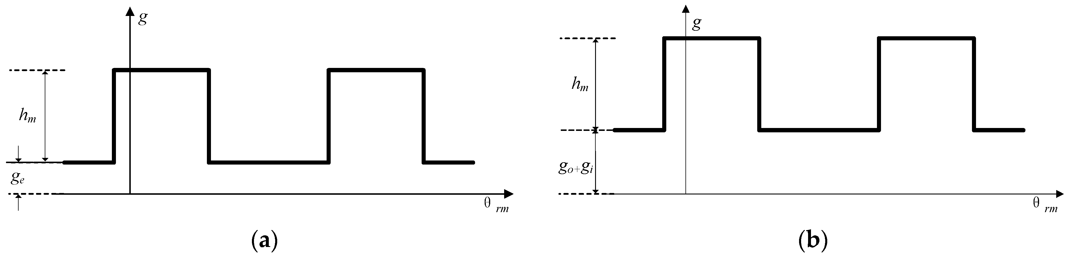
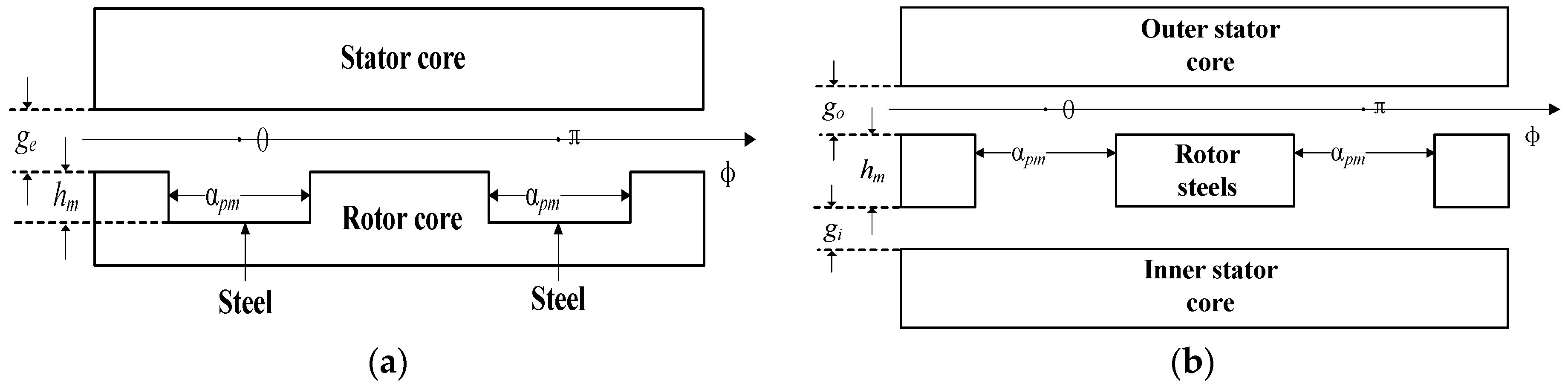
Figure 3 presents the air gap structures in the BDFRM and DSFM motor with an ideal stator surface around the rotor. The air gaps in the two motors were assumed to be uniform, implying that the air gap length between the stator and the rotor teeth is
ge and that between the stator and the rotor yoke is
ge +
hm in
Figure 3a, that the air gap length between the two stator and the iron segments on the rotor is
go +
gi, and that between the outer stator and the inner stator is
go +
gi +
hm in
Figure 3b. Based on the preceding analyses, the air gap functions of the two motors are illustrated in
Figure 4.
According to
Figure 4a,b, the air gap function of the DSFM motor and that of the BDFRM are both periodic rectangular waves. The fundamental waves of the two air gap functions can be expressed as periodic sinusoidal waves using Fourier transform [
16]. Therefore, in the simplified discussion on dynamic model of the DSFM motor, the inverse machine air gap function can be modelled as follows [
17]:
where
pr is the number of rotor poles, θ is the mechanical angle around the periphery of the machine with respect to the primary A phase axis, and θ
rm is the rotor mechanical angle with reference to the primary A phase axis. The
m and
n in Equation (1) are two constants in the Fourier series, and they differ from the two different air gap structures, which means that the two motors have similar air gap functions regardless of the constants.
According to the first principle-based rigorous development of dynamic equations for the BDFRM, the equations for the primary and secondary windings of the DSFM motor in a stationary reference frame (denoted with the sub-subscript s) are [
17]:
where the primary winding is the winding of outer stator, and the secondary winding is the winding of inner stator in this paper.
The torque expression in the stationary reference frame is [
17]:
Two
dq reference frames are needed to convert the equations in the stationary frame to the corresponding rotating frame equations because the frequencies of the two windings in the DSFM motor are different. Assuming that the angle of the primary reference frame is θ, the angle of the secondary reference frame is θ
r−θ, the conversion formulas can be written as:
Substituting the above equations into Equation (2), the dynamic model of the DSFM motor in the rotating
dpqp and
dsqs reference frames through strict deductions can be represented as:
The torque expression is:
3. Experiments Conducted Using the Variable Voltage and Variable Frequency (VVVF) Control
The prototype of the DSFM motor was developed experimentally; the test machine and its controller are shown in
Figure 5. The DSFM motor specifications are summarized in
Table 1. The back-to-back controller is comprised of two converters for simultaneously controlling the outer and inner windings.
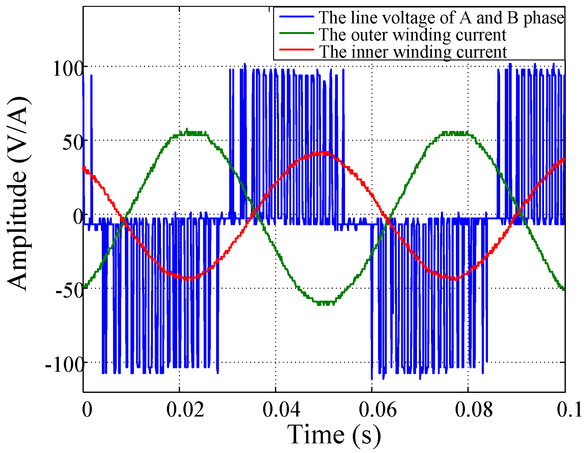
The VVVF control was implemented to verify the operating principles of the DSFM motor, and the result is shown in
Figure 6. The rotor speed was 212 rpm when the frequencies of the outer and inner winding current were
fp = 20 Hz and
fs = 20 Hz, respectively. Several frequency supplies were then tested using the VVVF control. The results are summarized in
Table 2.
From the test results shown in
Table 2, one can get the relation among the frequencies of the two windings and the rotor speed:
The differences between the theoretical and real speeds listed in
Table 2 were due to the inaccurate speed control of the open loop VVVF control.
4. Stator-Current-Oriented Vector Control (SCOVC)
Two additional formulas can be deduced from Equation (7).
where ω
p is the angular frequency of the primary winding current, ω
s is the angular frequency of the secondary winding current, and ω
rm is the mechanical angular velocity of the rotor.
where θ
p, θ
s, and θ
r are the electric angles of the primary winding current, secondary winding current, and rotor, respectively.
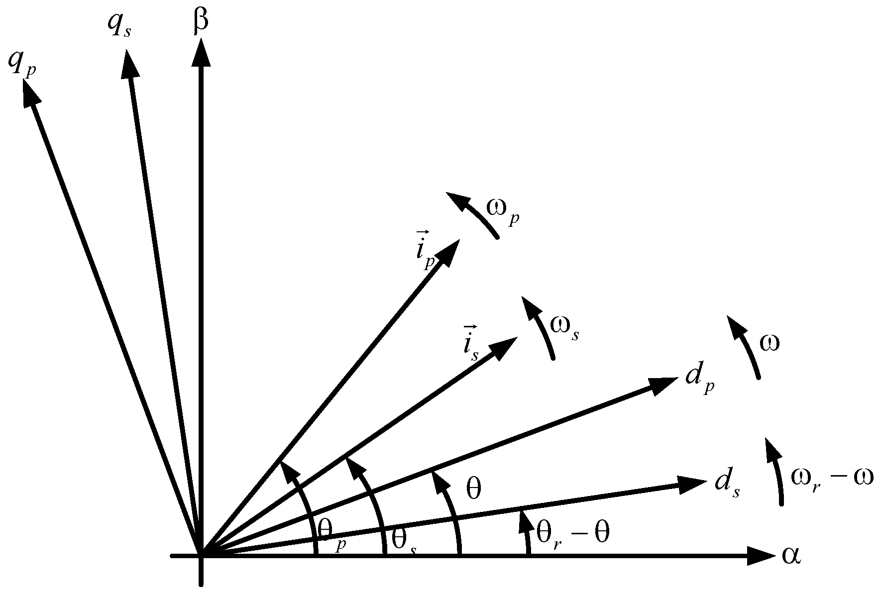
According to the analysis of the vector relationship between the two stator windings and rotor in the DSFM motor, the vector diagram of the DSFM motor can be represented as shown in
Figure 7 [
17].
The decoupled control of the DSFM motor orients the primary winding current vector
ip to the
dp axis, which implies:
where ω
r =
pr × ω
rm, and:
Thus, the secondary winding current vector ip can be automatically oriented to the ds axis.
The decoupled voltage equations of the DSFM motor become:
The primary equations are obviously in the ωp frame, and the secondary ones are in the ωs frame. Therefore, this selection moves each of the equations into their “natural” reference frames where the respective vector components appear as DC in the steady state. This decoupled control method proposed in this paper is called SCOVC.
Based on the preceding basic analysis of the dynamic model and vector relationship of the DSFM motor, two SCOVC methods with different excitation were investigated and implemented as follows.
4.1. SCOVC with DC Excitation
4.1.1. Theoretical Analysis
If ω
p in Equation (11) is equal to 0, which implies that a DC current is inputted in the primary winding, the angle of the primary reference frame θ is equal to
0, then according to Equation (4), the conversion formulas of the primary frame become:
Meanwhile,
ipq* = 0 control was implemented to realize θ
p = θ
= 0. Substituting this value into Equation (13) yields:
and the conversion formulas of the secondary frame become:
That is, a stationary
dq reference frame for the primary equation and a rotor reference frame for the secondary equation. The SCOVC method with DC excitation is simply called DC excitation control in the following text. The DC excitation control method for the DSFM motor is illustrated in
Figure 8.
With the direct given current vector in the primary winding, the flux linkage produced by the primary winding current was stationary and constant, and its value could be adjusted by varying the
ipd*. The primary winding current vector was set stationary and the secondary winding current vector was oriented by θ
r. Moreover, the maximum torque per ampere (MTPA) strategy was used to control the secondary winding current
isd* and
isq*. For the DC excitation control, Equation (6) becomes:
The decoupled control of Te was realized through isq according to Equation (18); moreover, the torque capacity could be increased by controlling the DC excitation in the primary winding.
4.1.2. Simulation Studies
The simulation studies of the proposed DC excitation control method were carried out in Matlab Simulink using the DSFM motor data from
Table 1 obtained by Maxwell model. The simulation results in
Figure 9 have been successfully experimentally verified by the corresponding experiments. Both the simulation results and the experimental results will be jointly discussed in the following section.
4.1.3. Experimental Results
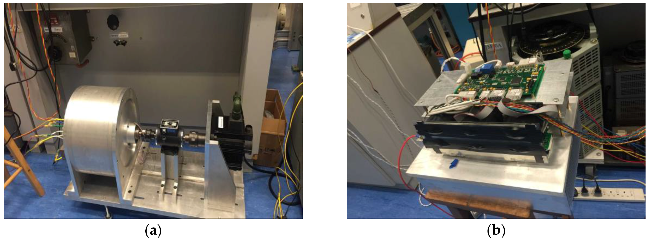
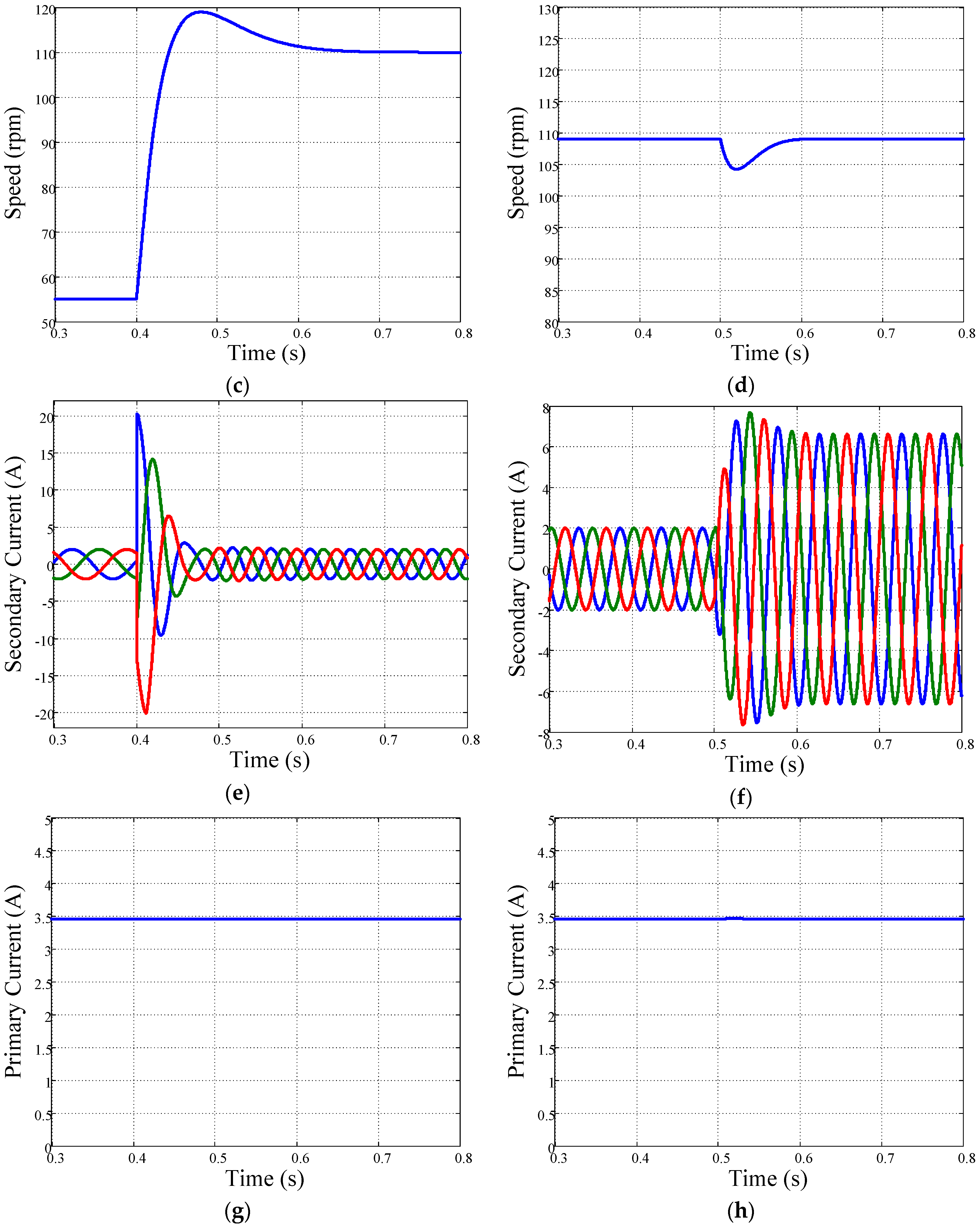
Figure 10a,b shows the actual DSFM motor test rig and schematic of its constituent parts, respectively.
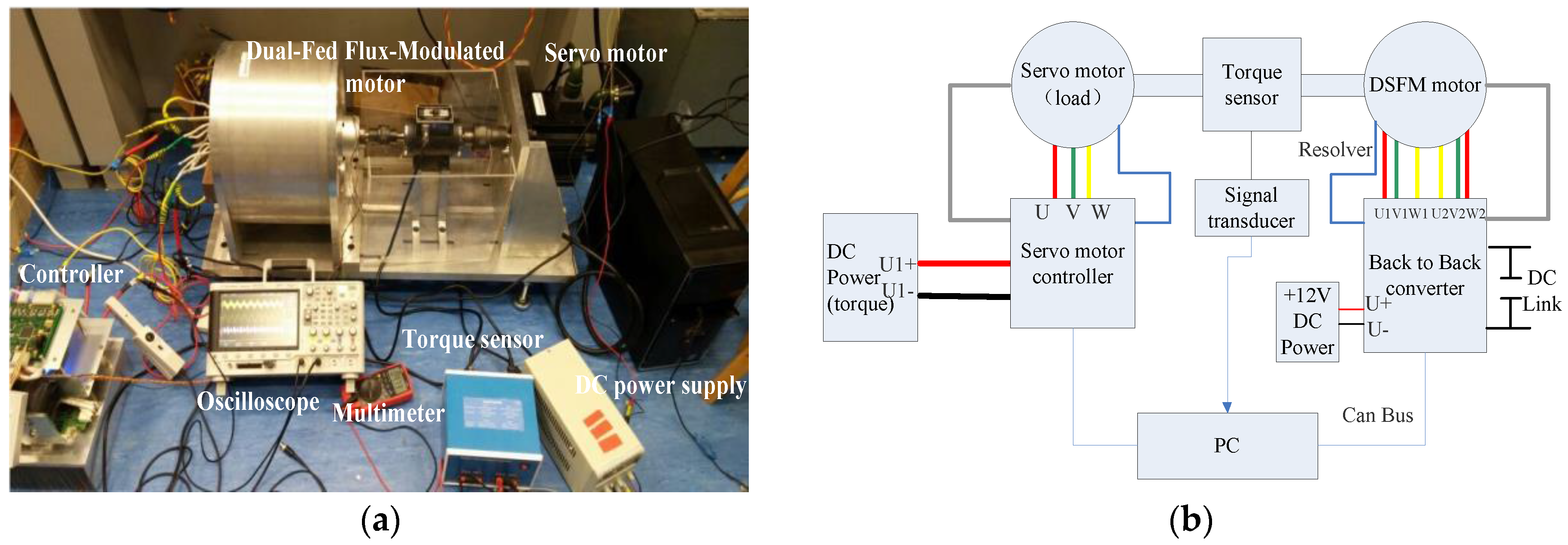
The DSFM motor can operate stably with DC excitation in the primary winding. The current curves of the DSFM motor at 200 rpm and 3 Nm are shown in
Figure 11.
As shown in
Figure 11a, the secondary current was asymmetric sine wave and was stable at 36.6 Hz when the DC current in the primary winding was 8 A and the given speed was 200 rpm. The harmonic content of the current was low as shown in
Figure 11b.
To evaluate the performance of the proposed control method of the DSFM motor, the speed response was analysed by changing the given speed or increasing the load torque, and the corresponding phase currents in both the primary and secondary windings were measured. The experimental results are shown in
Figure 12.
According to
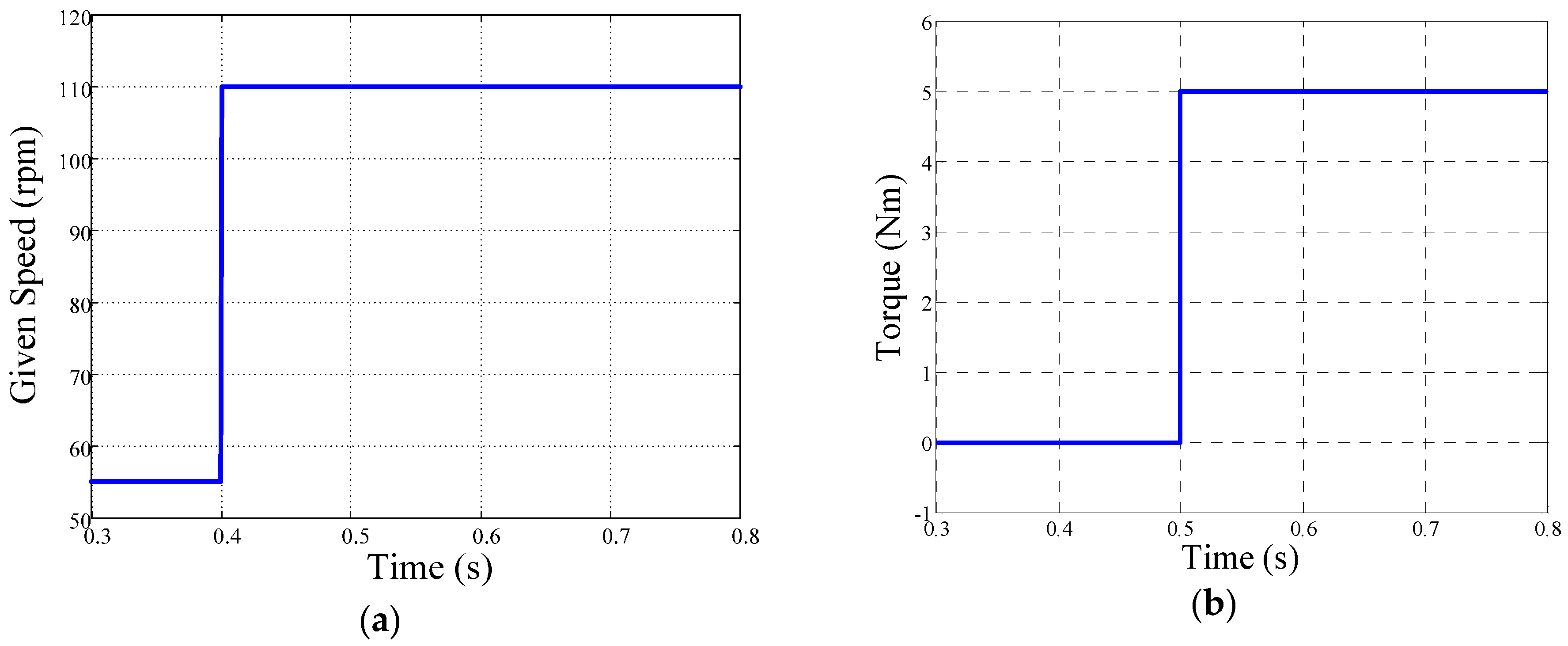
Figure 12a, the given speed was increased from 55 to 110 rpm at 1 s; the final speed was stable at 110 rpm. In
Figure 12c, the rotor speed was changed by a slow progressive change of the PI control. The secondary winding current was changed during the adjustment period, and the stability was restored by increasing the frequency only twice from 10 to 20 Hz, as shown in
Figure 12e. The primary winding current was maintained at a constant value, as shown in
Figure 12g, because a DC current was supplied to the primary winding all the time. The steady state errors of the speed were less than 5 rpm.
By maintaining the given speed at 109 rpm and increasing the load torque from 0 to 5 Nm at 5 s shown in
Figure 12b, the speed of the DSFM motor changed to 109 rpm accurately through a period of adjustment. The speed curve is presented in
Figure 12d. The plot in
Figure 12f illustrates that the amplitude of the secondary winding current was increased with this load torque, and its frequency was maintained at 20 Hz. The increase in the secondary winding current resulted from the increase in
isq, thus enhancing the electromagnetic torque of the DSFM motor
Te as predicted by Equation (18). The current in the primary winding was maintained at a constant value, as shown in
Figure 12h. The measured and simulated results in
Figure 9 are mostly identical to the experimental. The simulated speed responses were better than the experimental because the PI parameters for speed control experiment were not ideal.
4.1.4. Discussion
According to the preceding simulation and experiment results, the proposed DC excitation control can realize the decoupled control for the current of the two stator windings and the electromagnetic torque Te. For this control method, the DSFM motor can always operate under motoring conditions similar to PMSMs, which allows the application of the DSFM motor to EVs.
4.2. SCOVC with AC Excitation
4.2.1. Theoretical Analysis
If ω
p in Equation (11) is not equal to 0 then, according to Equation (4), the conversion formulas of the primary frame become:
and the conversion formulas of the secondary become:
This relationship must be satisfied at any time so that the secondary frame can be oriented according to the rotor angle θ
r and angle of the primary winding current θ
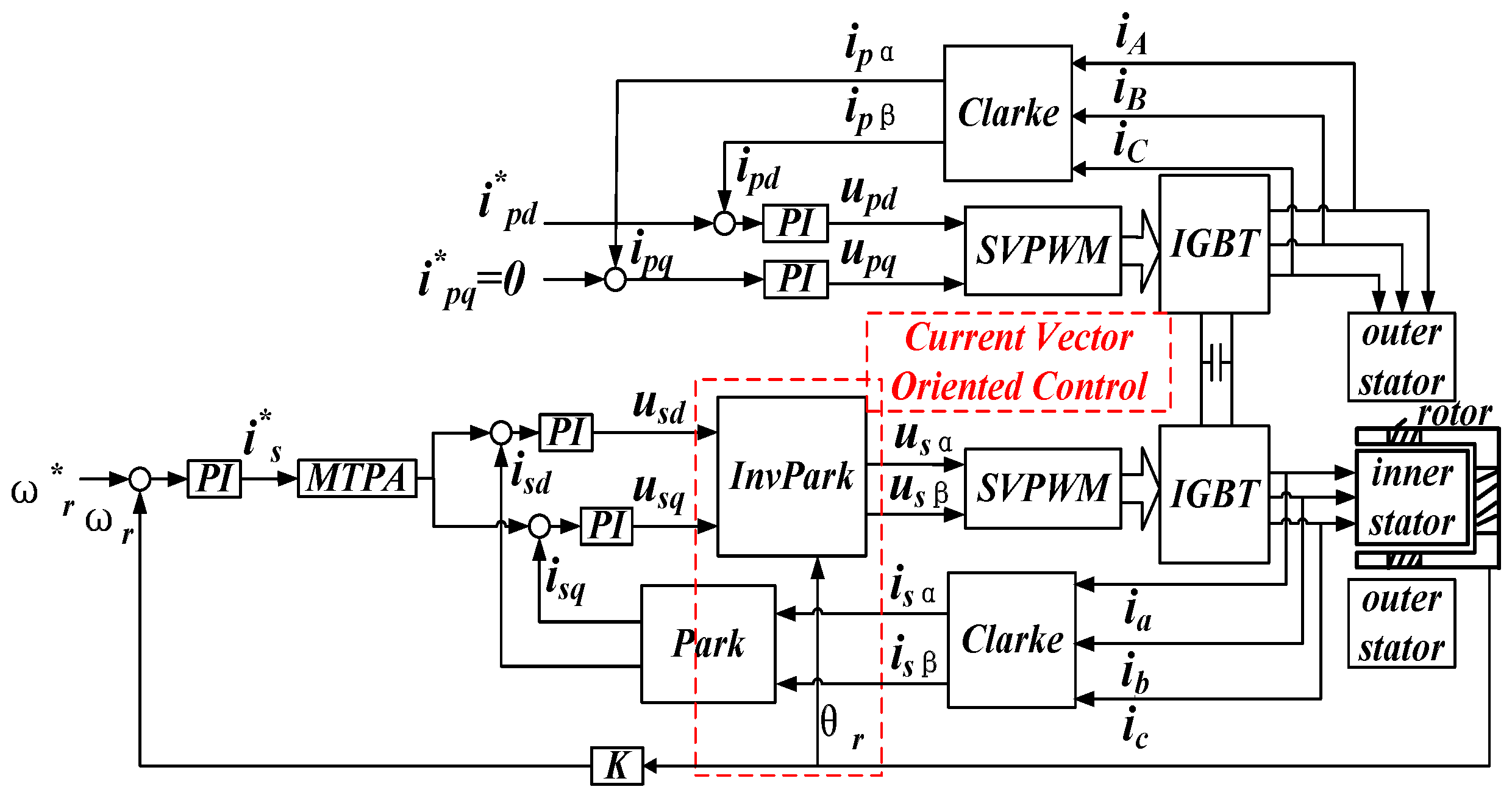
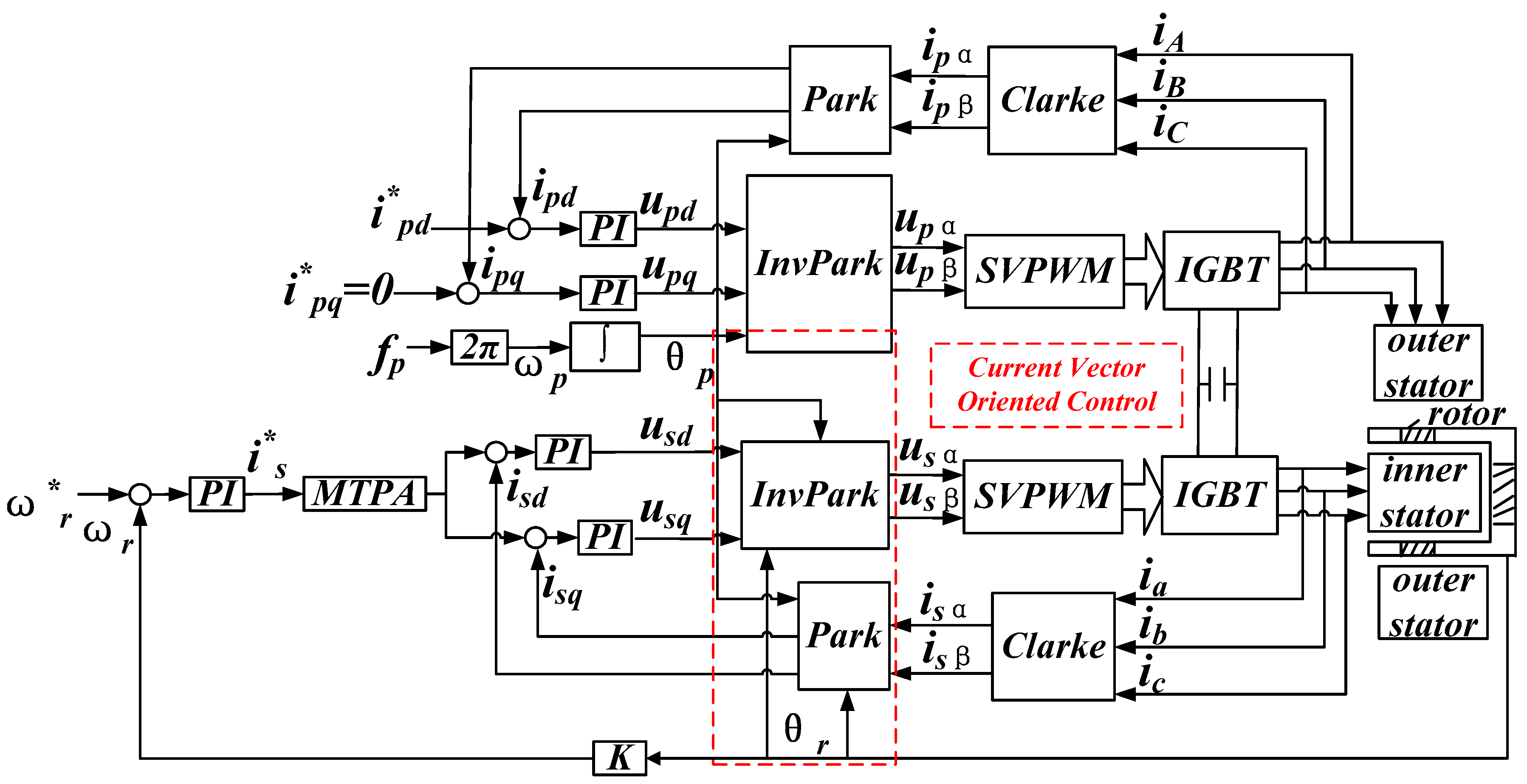
p. The SCOVC with AC excitation is referred to as AC excitation control in the following text. The AC excitation control method for the DSFM motor is illustrated in
Figure 13.
The current closed loop control with a given fp was implemented to produce a rotating magnetic field with angular velocity ωp, and the primary winding current phase angle θp was established after the integral link. The secondary winding current phase angle θs was then obtained according to Equation (13). Thus, the secondary winding current vector is was oriented to the ds axis by θs. The two winding current vectors were oriented throughout the AC excitation control method. Moreover, the frequency of the secondary winding changed to fs with a known θr, which implied that the speed control of the DSFM motor was indirectly conducted using the frequency of the secondary winding current. For example, if ωr* = 218 rpm and fp = 20 Hz, fs = 20 Hz can be exactly acquired using the algorithm of the proposed control method, and the rotor can be operated accurately at 218 rpm. Moreover, the MTPA control was used to realize the decoupled control of Te, which was expressed using Equation (18).
4.2.2. Simulation Results
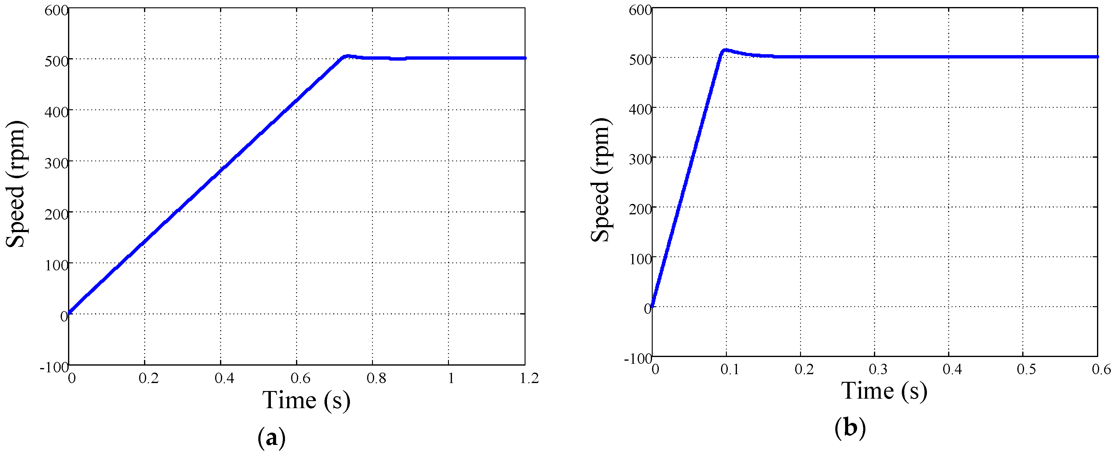
To fully test the performance of the proposed control strategy, start-up of the motor under load was simulated, and the results are shown in
Figure 14. The given speed was 500 rpm and the load torque was 1.4 Nm.
Note from
Figure 14 that when the primary current
i*pd increased, the starting torque increased and the starting time decreased. The start-up simulation illustrates that
Te can be controlled not only by the secondary current
i*sq, but also by the primary current
i*pd, one can choose the better control method according to the actual situation.
More simulation studies of the proposed AC excitation control method were carried out and experimentally verified by the corresponding experiments. The simulation results are shown in
Figure 15, and agree well with the experimental results. The corresponding plots will be jointly discussed in the next section.
4.2.3. Experimental Results
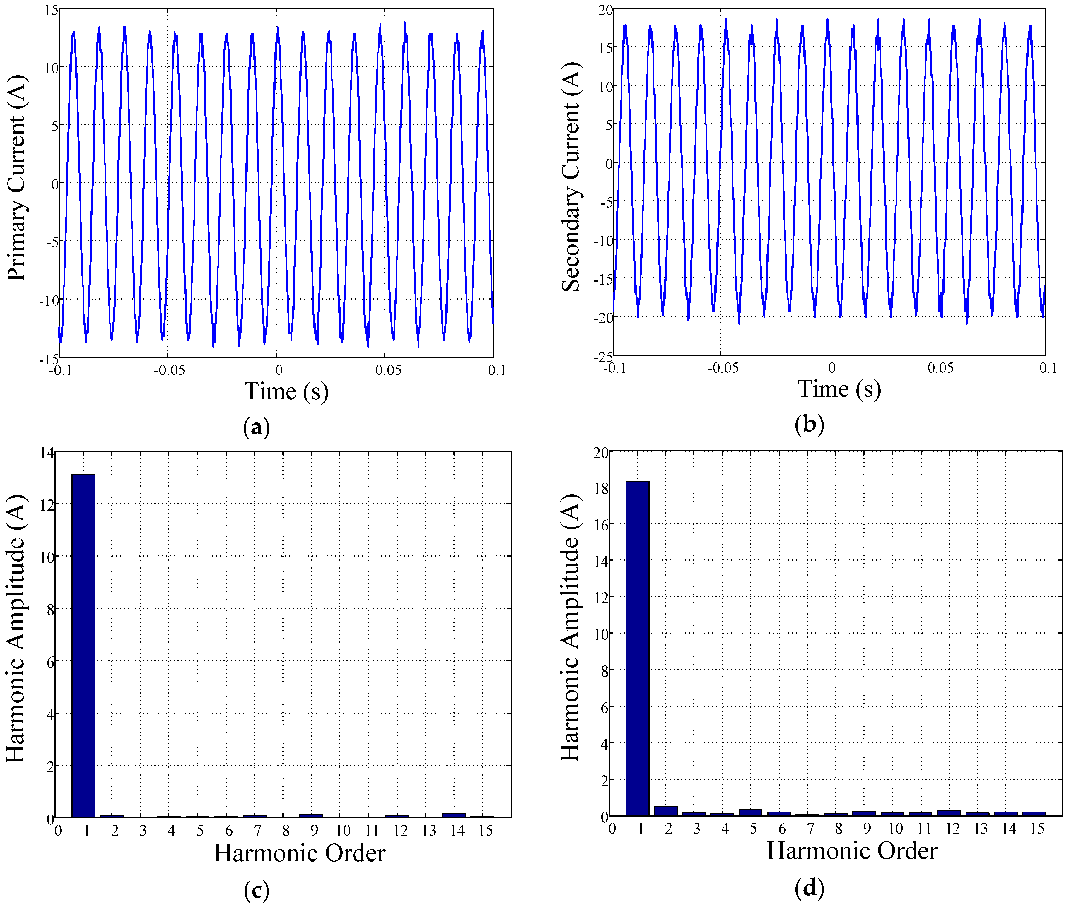
The DSFM motor can operate at different speeds with different load torques. The current curves of the DSFM motor at 924 rpm and 3 Nm are shown in
Figure 16.
As shown in
Figure 16a,b, the two winding currents are asymmetric sine waves and are stable at 85 Hz when the given speed was 924 rpm. The harmonic content of the currents were both low as shown in
Figure 16c,d.
Then the speed responses and phase currents are illustrated in
Figure 17.
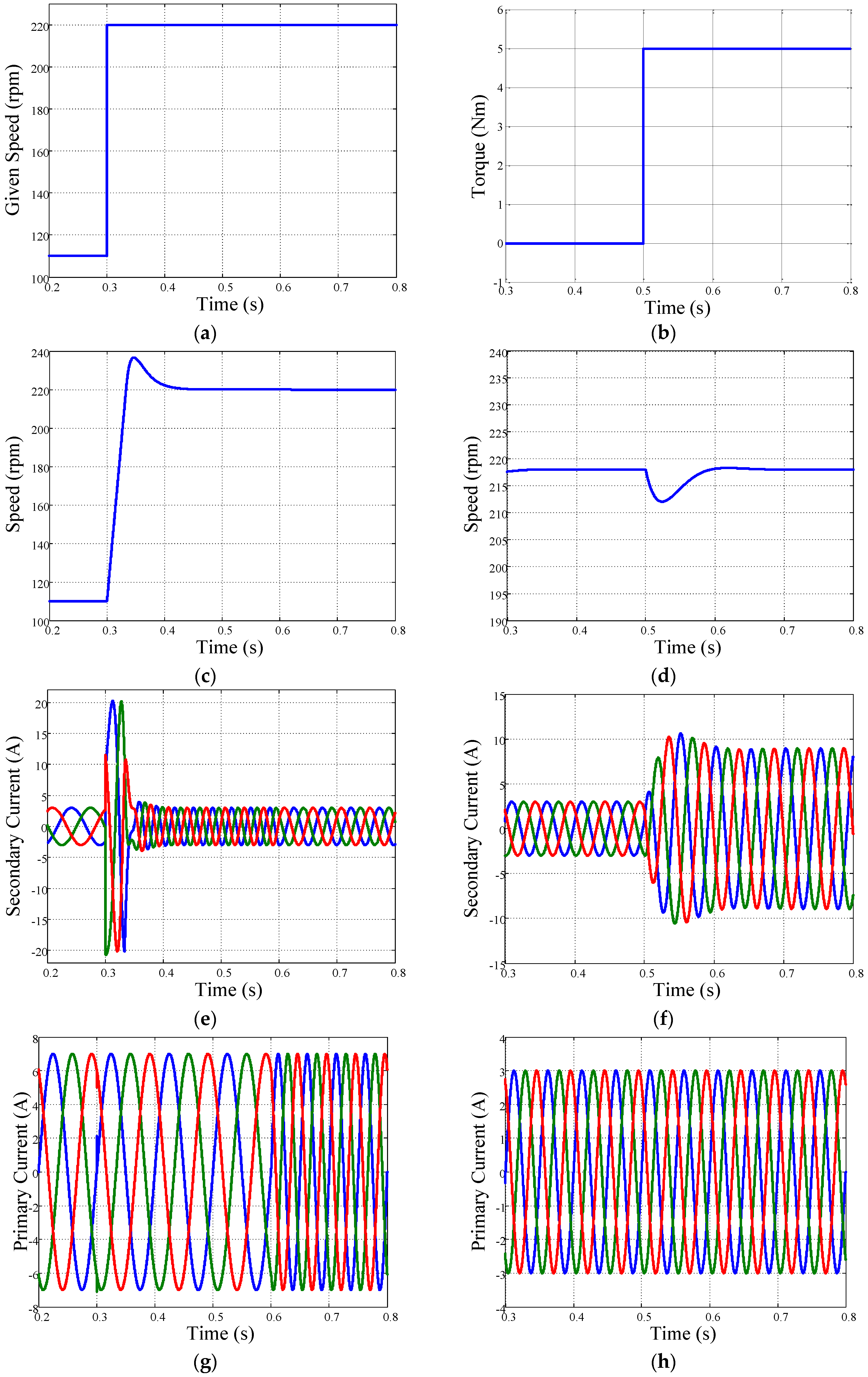
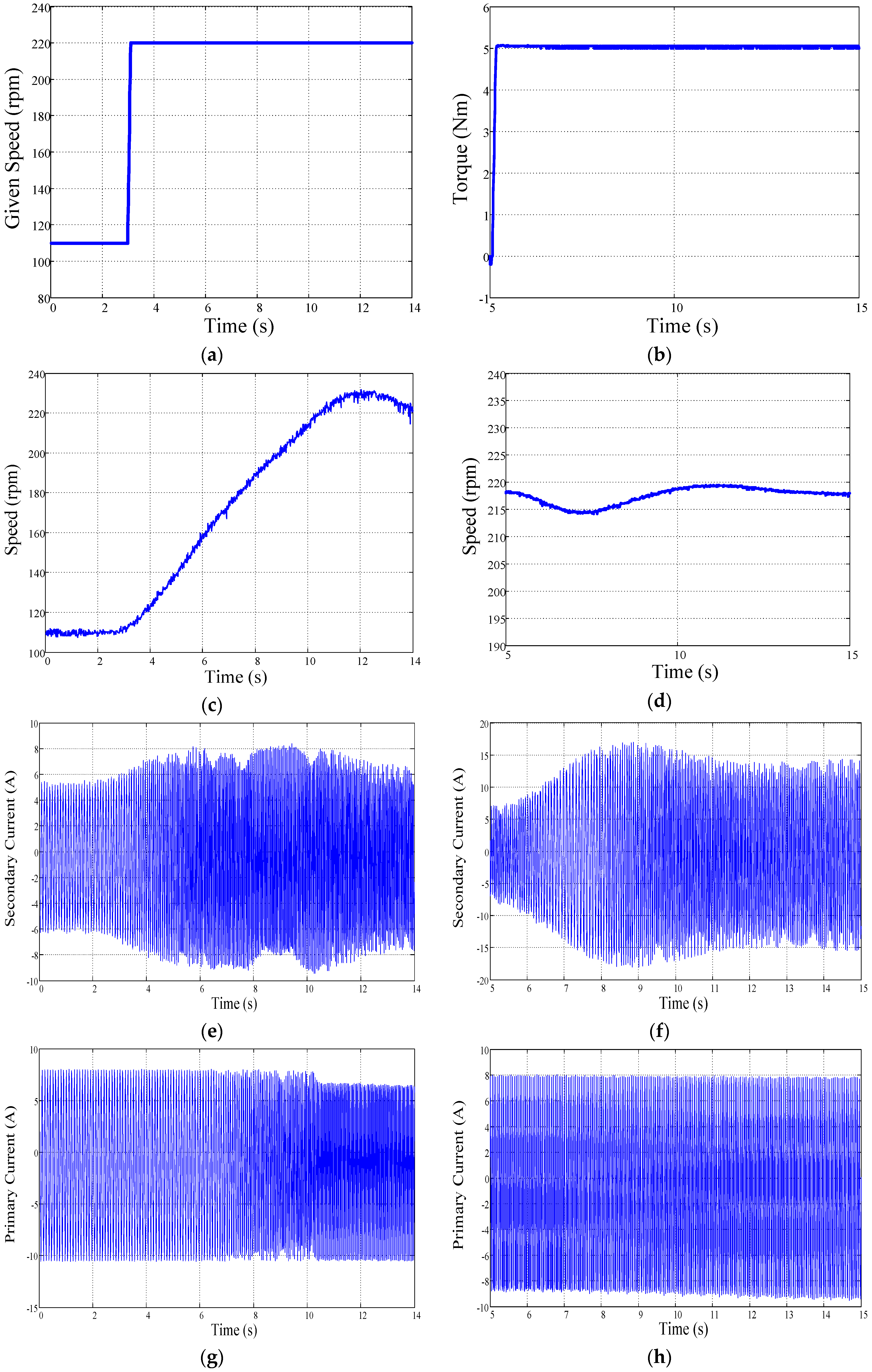
There are two processes in the AC excitation control experiments as shown in
Figure 17a. First, the given speed was increased from 110 to 220 rpm at 3 s. Second, the frequency of primary winding current was increased from 10 to 20 Hz at 8 s. According to
Figure 17c, the final speed was stable at 220 rpm throughout a slow progressive change of the PI control. The secondary winding current changed during the two periods of adjustment. First, from 3–8 s, its frequency increased from 10 to 30 Hz. Second, from 8–10 s, its frequency decreased from 30 to 20 Hz, and was finally stable after 14 s. The secondary current curve is shown in
Figure 17e. The amplitude of the primary winding current restored stability and the frequency was changed to 20 Hz through an adjustment period of 2 s from 8–10 s as shown in
Figure 17g. The steady state errors of the speed were less than 5 rpm.
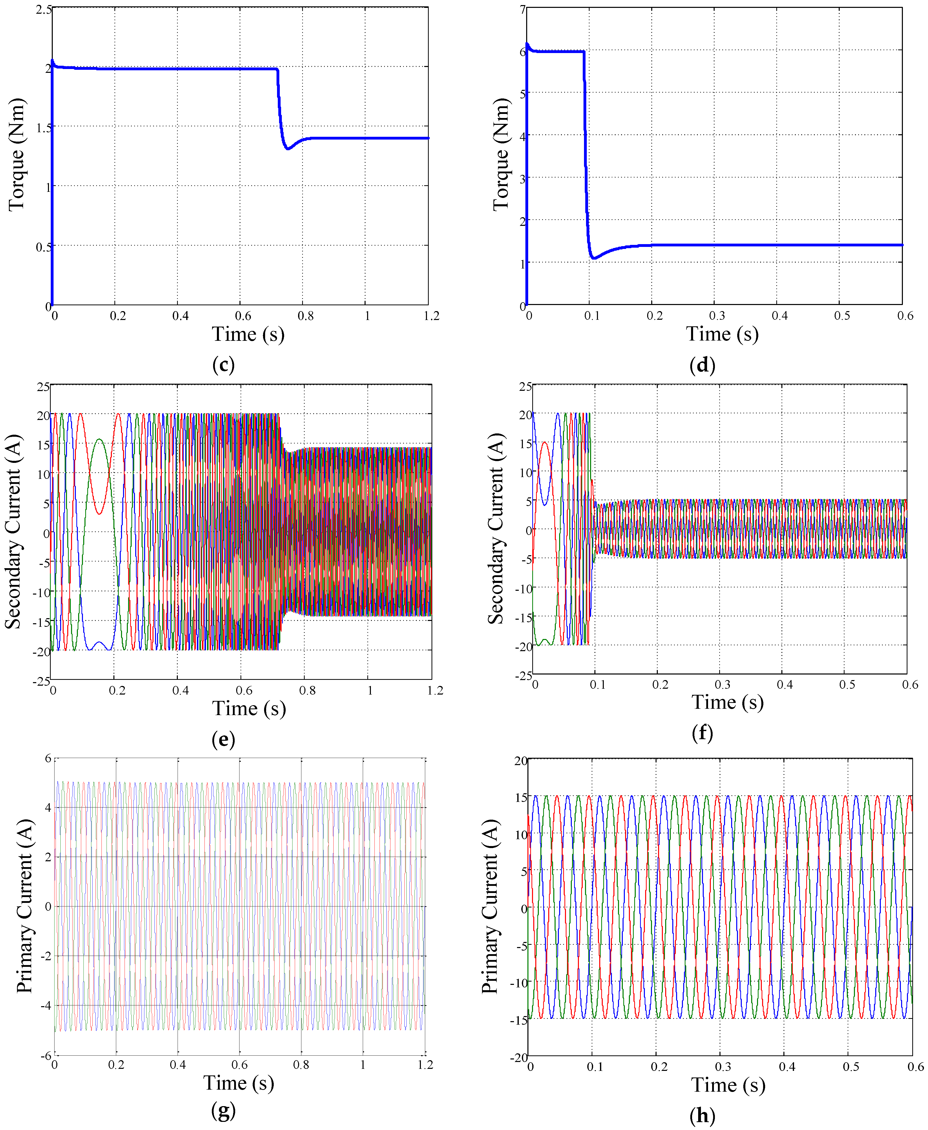
By maintaining the given speed at 218 rpm and increasing the load torque from 0 to 5 Nm at 5 s shown in
Figure 17b, the speed of the DSFM motor changed to 218 rpm accurately through a period of adjustment. The speed curve is presented in
Figure 17d. The plot in
Figure 17f illustrates that the amplitude of the secondary winding current was increased using this load torque, and its frequency was maintained at 20 Hz. The current in the primary winding was controlled using the current closed loop control presented in
Figure 11 and maintained constant, as shown in
Figure 17h. The same speed, frequency and load torque change was implemented as shown in
Figure 15, and the results are also the same. The speed can be strictly controlled by the speed closed loop control, and the frequency of the two winding currents can be automatically adjusted through the AC excitation control method.
4.2.4. Discussion
The experimental results showed high speed response with the change in speed and load torque, which illustrated that the DSFM motor can operate stably and reliably under different conditions. The wide speed range of the DSFM motor can be achieved without flux-weakening control such that the copper loss can be reduced and the efficiency can be increased at a high speed compared with PMSMs. Thus, the proposed control can meet the requirement of high-speed operation and efficient torque control, and would have great application prospects in EVs.
5. Conclusions
This study explored and investigated the control strategies for the application of the DSFM motor to EVs. Two available vector control methods were proposed and control system effects were validated using a customised DSFM prototype.
The differences in air gap structures of the DSFM and BDFM motors were compared and analysed, and the mathematical model of the DSFM motor was used as the basis of the decoupled control method.
The VVVF control was implemented to explore and verify the operating principles of the DSFM motor. According to the experimental results of the VVVF control, the speed and torque of the DSFM motor can be controlled using the frequency of the current in the two stator windings.
The SCOVC with DC excitation control method was realized theoretically and experimentally, and high speed and torque performance were obtained through the variable speed and torque tests.
The SCOVC with AC excitation control method was realized theoretically and experimentally, and high speed and torque performance were obtained through the variable speed and torque tests.
The DSFM motor and its control strategies proposed in this paper can serve as a basis for further research on application of the flux-modulated motor to EVs, and can be crucial for more applications of such motors.
The DC excitation control had a limited range of frequency, while the AC one did not. Thus, the two closed loop controls can be flexibly applied to different situations. For example, in generator mode, the DSFM motor can be used as a DC generator with the DC one or an AC generator with the AC one, and in motor mode, it can be used as a slow speed motor with the DC one or a high speed motor with the AC one. The proposed control methods will be implemented on an electric bus being developed in our laboratory.
Acknowledgments
This study was supported in part by the National Science Foundation of China (51477058), Science and Technology Plan Project of Xiamen (3502Z20153029), and Promotion Program for Young and Middle-aged Teacher in Science and Technology Research of Huaqiao University (ZNQ-YX304).
Author Contributions
Xinhua Guo and Weinong Fu conceived and designed the experiments; Shaozhe Wu, Yunchong Wang, and Peihuang Zeng performed the experiments; Shaozhe Wu performed the simulations; Shaozhe Wu and Yulong Liu analysed the data; and Xinhua Guo wrote the paper.
Conflicts of Interest
The authors declare no conflict of interest.
Abbreviations
The following abbreviations are used in this paper:
| DSFM | Dual-stator flux-modulated |
| BDFMs | Brushless doubly-fed machines |
| BDFG | Brushless doubly-fed generator |
| BDFRM | Brushless doubly-fed reluctance machine |
| EV | Electric vehicle |
| SCOVC | Stator-current-oriented vector control |
| DC | Direct current |
| AC | Alternating current |
| VC | Voltage vector-oriented control |
| FOC | Field-oriented control |
| PMSMs | Permanent magnet synchronous motors |
| VVVF | Variable voltage and variable frequency |
| MTPA | Maximum torque per ampere |
References
- Long, B. Energy-regenerative braking control of electric vehicles using three-phase brushless direct-current motors. Energies 2014, 7, 99–114. [Google Scholar] [CrossRef]
- Cheng, M.; Sun, L.; Buja, G.; Song, L.H. Advanced electrical machines and machine-based systems for electric and hybrid vehicles. Energies 2015, 8, 9541–9564. [Google Scholar] [CrossRef]
- Chan, C.C. The state of the art of electric, hybrid, and fuel cell vehicles. Proc. IEEE 2007, 95, 704–718. [Google Scholar] [CrossRef]
- Chan, C.C.; Wong, Y.S. The state of the art of electric vehicles technology. In Proceedings of the 4th International Power Electronics and Motion Control Conference, Xi’an, China, 14–16 August 2004; pp. 46–57.
- Wang, Y.C.; Ho, S.L.; Fu, W.N.; Shen, J.X. A novel brushless doubly fed generator for wind power generation. IEEE Trans. Magn. 2012, 48, 4172–4175. [Google Scholar] [CrossRef]
- Knight, A.; Betz, R.; Dorrell, D.G. Design and analysis of brushless doubly fed reluctance machines. IEEE Trans. Ind. Appl. 2013, 49, 50–58. [Google Scholar] [CrossRef]
- Hsieh, M.F.; Lin, I.H.; Dorrell, D.G. Magnetic circuit modeling of brushless doubly-fed machines with induction and reluctance rotors. IEEE Trans. Magn. 2013, 49, 2359–2362. [Google Scholar] [CrossRef]
- Roberts, P.; Long, T.; McMahon, R.; Shao, S.; Abdi, E.; Maciejowski, J. Dynamic modelling of the brushless doubly fed machine. IET Elect. Power Appl. 2013, 7, 544–556. [Google Scholar] [CrossRef]
- Knight, A.M.; Betz, R.E.; Song, W.K.; Dorrell, D.G. Brushless doubly-fed reluctance machine rotor design. In Proceedings of the IEEE Energy Conversion Congress and Exposition (ECCE), Raleigh, NC, USA, 15–20 September 2012; pp. 2308–2315.
- Logan, T.; McMahon, R.; Seffen, K. Noise and vibration in brushless doubly fed machine and brushless doubly fed reluctance machine. IET Elect. Power Appl. 2013, 8, 50–59. [Google Scholar] [CrossRef]
- Jovanovic, M. Sensored and sensorless speed control methods for brushless doubly fed reluctance motors. IET Elect. Power Appl. 2009, 3, 503–513. [Google Scholar] [CrossRef]
- Ademi, S.; Jovanovic, M. Vector control strategies for brushless doubly-fed reluctance wind generators. In Proceedings of the 2nd International Symposium on Environment-Friendly Energies and Applications (EFEA), Newcastle upon Tyne, UK, 25–27 June 2012; pp. 44–49.
- Ademi, S.; Jovanovic, M. Theoretical and experimental evaluation of vector control for doubly-fed reluctance generators. In Proceedings of the International Conference on Electrical Machines (ICEM), Berlin, Germany, 2–5 September 2014; pp. 936–942.
- Ademi, S.; Jovanovic, M. Maximum torque per inverter ampere control of brushless doubly-fed reluctance generators for wind turbines. In Proceedings of the International Symposium on Power Electronics, Electrical Drives, Automation and Motion (SPEEDAM), Ischia, Italy, 18–20 June 2014; pp. 883–888.
- Ademi, S.; Jovanovic, M.; Hasan, M. Control of brushless doubly-fed reluctance generators for wind energy conversion systems. IEEE Trans. Energy Convers. 2015, 30, 596–604. [Google Scholar] [CrossRef]
- Neti, P.; Nandi, S. Determination of effective air-gap length of synchronous reluctance motors (SynchRel) from experimental data. IEEE Trans. Ind. Appl. 2006, 4, 454–464. [Google Scholar] [CrossRef]
- Betz, R.E.; Jovanovic, M.G. Introduction to the space vector modeling of the brushless doubly fed reluctance machine. Elect. Power Compnt. Syst. 2003, 31, 729–755. [Google Scholar] [CrossRef]
Figure 1.
Structure of the DSFM motor with an iron segment rotor: (a) 3D model; and (b) 2D model.
Figure 1.
Structure of the DSFM motor with an iron segment rotor: (a) 3D model; and (b) 2D model.
Figure 2.
A structural diagram of the BDFRM (G) drive setup.
Figure 2.
A structural diagram of the BDFRM (G) drive setup.
Figure 3.
Air gap structures of the (a) BDFRM motor and (b) DSFM motor.
Figure 3.
Air gap structures of the (a) BDFRM motor and (b) DSFM motor.
Figure 4.
Air gap function of the (a) BDFRM motor and (b) DSFM motor.
Figure 4.
Air gap function of the (a) BDFRM motor and (b) DSFM motor.
Figure 5.
Prototype of the DSFM motor and its controller: (a) test machine; and (b) back-to-back controller.
Figure 5.
Prototype of the DSFM motor and its controller: (a) test machine; and (b) back-to-back controller.
Figure 6.
Experimental results of the VVVF control.
Figure 6.
Experimental results of the VVVF control.
Figure 7.
Reference frames and current vectors used in DSFM motor equations.
Figure 7.
Reference frames and current vectors used in DSFM motor equations.
Figure 8.
DC excitation control method.
Figure 8.
DC excitation control method.
Figure 9.
Simulation results of the DC excitation control for the DSFM motor: (a) curve of the given speed variation; (b) curve of the load torque variation; (c) speed curve for speed varying from 55 to 110 rpm; (d) speed curve for torque varying from 0 to 5 Nm; (e) secondary current curve for speed varying from 55 to 110 rpm; (f) secondary current curve for torque varying from 0 to 5 Nm; (g) primary current curve for speed varying from 55 to 110 rpm; and (h) primary current curve for torque varying from 0 to 5 Nm.
Figure 10.
Experimental environment of the DSFM motor: (a) laboratory test facility; and (b) block diagram of the DSFM motor experimental setup.
Figure 10.
Experimental environment of the DSFM motor: (a) laboratory test facility; and (b) block diagram of the DSFM motor experimental setup.
Figure 11.
Winding currents of the DSFM motor at 200 rpm: (a) secondary winding current; and (b) the harmonic content of the current.
Figure 11.
Winding currents of the DSFM motor at 200 rpm: (a) secondary winding current; and (b) the harmonic content of the current.
Figure 12.
Experimental results of the DC excitation control for the DSFM motor: (a) curve of the given speed variation; (b) curve of the load torque variation; (c) speed curve for speed varying from 55 to 110 rpm; (d) speed curve for torque varying from 0 to 5 Nm; (e) secondary current curve for speed varying from 55 to 110 rpm; (f) secondary current curve for torque varying from 0 to 5 Nm; (g) primary current curve for speed varying from 55 to 110 rpm; and (h) primary current curve for torque varying from 0 to 5 Nm.
Figure 13.
AC excitation control method.
Figure 13.
AC excitation control method.
Figure 14.
Simulation results of the start-up of the motor under load: (a) speed curve for i*pd = 5 A; (b) speed curve for i*pd = 15 A; (c) torque curve for i*pd = 5 A; (d) torque curve for i*pd = 15 A; (e) secondary current curve for i*pd = 5 A; (f) secondary current curve for i*pd = 15 A; (g) primary current curve for i*pd = 5 A; and(h) primary current curve for i*pd = 15 A.
Figure 15.
Simulation results of the AC excitation control for the DSFM motor: (a) curve of the given speed variation. (b) curve of the load torque variation; (c) speed curve for speed varying from 110 to 220 rpm; (d) speed curve for torque varying from 0 to 5 Nm; (e) secondary current curve for speed varying from 110 to 220 rpm; (f) secondary current curve for torque varying from 0 to 5 Nm; (g) primary current curve for speed varying from 110 to 220 rpm; and (h) primary current curve for torque varying from 0 to 5 Nm.
Figure 16.
Winding currents of the DSFM motor at 924 rpm: (a) primary winding current; (b) secondary winding current; (c) the harmonic content of the primary current; and (d) the harmonic content of the secondary current.
Figure 16.
Winding currents of the DSFM motor at 924 rpm: (a) primary winding current; (b) secondary winding current; (c) the harmonic content of the primary current; and (d) the harmonic content of the secondary current.
Figure 17.
Experimental results of the AC excitation control for the DSFM motor: (a) curve of the given speed variation. (b) curve of the load torque variation; (c) speed curve for speed varying from 110 to 220 rpm; (d) speed curve for torque varying from 0 to 5 Nm; (e) secondary current curve for speed varying from 110 to 220 rpm; (f) secondary current curve for torque varying from 0 to 5 Nm; (g) primary current curve for speed varying from 110 to 220 rpm; and (h) primary current curve for torque varying from 0 to 5 Nm.
Table 1.
DSFM motor prototype parameters and ratings.
Table 1.
DSFM motor prototype parameters and ratings.
| Parameter | Value |
|---|
| Inner winding pole pairs | 5 |
| Outer winding pole pairs | 6 |
| Rotor pole pairs | 11 |
| Inner resistance (Ω) | 0.08 |
| Outer resistance (Ω) | 0.1 |
| Outer inductance (mH) | 4 |
| Inner inductance (mH) | 3 |
| Mutual inductance (mH) | 0.8 |
| Rated speed (rpm) | 924 |
| Maximum speed (rpm) | 1300 |
Table 2.
Test results of the VVVF control.
Table 2.
Test results of the VVVF control.
| Frequency (Hz) | Theoretical Speed (rpm) | Real Speed (rpm) |
|---|
| fp = fs = 9 | 98 | 96 |
| fp = fs = 20 | 218 | 212 |
| fp = fs = 54 | 589 | 560 |
| fp = fs = 72 | 785 | 748 |
| fp = fs = 85 | 927 | 883 |
| fp = fs = 89 | 970 | 924 |
© 2016 by the authors; licensee MDPI, Basel, Switzerland. This article is an open access article distributed under the terms and conditions of the Creative Commons Attribution (CC-BY) license (http://creativecommons.org/licenses/by/4.0/).


