Article

Experimental Study of Crack Initiation and Extension Induced by Hydraulic Fracturing in a Tree-Type Borehole Array

1
State Key Laboratory of Coal Mine Disaster Dynamics and Control, Chongqing University, Chongqing 400044, China
2
National and Local Joint Engineering Laboratory of Gas Drainage in Complex Coal Seams, Chongqing University, Chongqing 400044, China
*
Author to whom correspondence should be addressed.
Energies 2016, 9(7), 514; https://doi.org/10.3390/en9070514
Submission received: 8 February 2016 / Revised: 4 May 2016 / Accepted: 4 May 2016 / Published: 30 June 2016

Abstract

:
High-pressure hydraulic fracturing technology in coal and coal bed methane mines can lead to roof and floor damage, and fracture initiation disorder that leads to a “blank area”, and other issues. A new method of hydraulic fracturing is proposed to increase the homogeneous permeability of coal in underground coalmines. Numerical and other simulation tests for different forms of a tree-type, branched borehole model are presented. The results show that the branched array causes cracks to initiate from the bottom of the array, and these extend along the direction of the adjacent boreholes. Generally, as the number of branched boreholes increases, the coal seam fracture network also increase, improving the distribution of the fracture network, making the fracturing effect better. The branched boreholes appear to reduce initiation pressure and, with increasing branches, the initiation pressure decreases. A model with four tree-type, branched boreholes leads to a reduction in initiation pressure of 69%. In terms of permeability improvement technology in underground coalmines, a branched hydraulic fracturing borehole array has the advantages of reducing initiation pressure, controlling crack initiation and extension, enhancing the fracturing effect and reducing the destruction of the roof and floor.

1. Introduction

Coal bed methane is unconventional gas stored in coal seams via primary adsorption, and is becoming increasingly important in the future of energy development in China, and globally. Coal bed methane also poses a major risk to the safety of coal production [1,2,3]. Further, with increasing mining depth, the characteristics of high gas content in the coal seams and low permeability increase significantly, and thus hydraulic fracturing becomes increasingly important. Among the current methods used for coal bed methane extraction, hydraulic fracturing is developing rapidly because of its relative simplicity and obvious effects. Among the many methods, cross-measure hydraulic fracturing [4] and slotted hydraulic fracturing are both widely used. However, these methods have shortcomings: high initiation pressure is required, they can cause severe damage to roof and floor, high construction costs are involved, there is an increasing proneness to coal and gas outburst, they can negatively affect subsequent excavation and support work, and crack initiation and extension is hard to control. Importantly, these methods may cause a single main crack, which may lead to a “blank area” (Figure 1) or which may simply close. This blank area can lead to a sharp reduction in gas extraction and low extraction efficiency. In current condition, there are two ways to improve hydraulic fracturing now, one way is to improve fracturing fluid [5,6], and the other way is to improve fracturing method [7,8]. In this paper, a method of tree-type hydraulic fracturing is proposed to increase the permeability of the coal seam homogeneously, and with reduction in or mitigation of the above negative effects.
Domestic and foreign scholars have widely researched crack initiation and propagation in relation to hydraulic fracturing. Zhang et al. [9] investigated crack propagation and growth in cross-measure hydraulic fracturing while Wang et al. [10] studied the cross-measure hydraulic fracturing crack extension law by numerical simulation. Lu et al. [11] established a model to evaluate the initial pressure of fracturing and undertook a field test for verification, and Olovyanny [12] established a mathematical model of coal seam hydraulic fracturing. Song et al. [13] studied the effects of natural fractures on hydraulic crack extension. Additionally, Lin et al. [14] summarized the law of crack extension around a slotted drilling array under different lateral pressure coefficients.
Rbeawi et al. [15] introduced new analytical models to investigate the pressure behavior and flow regimes of a horizontal well with multiple hydraulic fractures. Zhu et al. [16] established a predictive model for hydraulic fracture initiation with the oriented perforation technique while Li et al. [17] explored crack initiation by oriented perforation and discussed the necessary conditions for the formation of double fractures. However, there have been very few studies reporting on crack initiation and extension by tree-type borehole array hydraulic fracturing.
To study the effects of such an array, and study the impacts of different forms of tree-type branch borehole arrays, it is necessary to investigate crack extension and development and numerical simulation (and other simulations) to verify the potentially positive effects of this method on fracturing and ultimately efficient coal bed methane extraction.

2. Principles of Hydraulic Fracturing by a Tree-Type Borehole Array

Hydraulic fracturing in underground coalmines is used to homogeneously increase the transforming volume and the permeability of the coal seam. The tree-type array method is used to specifically drill branching boreholes at the bottom of a cross-measure fracturing borehole advanced into a coal seam (hence the name). The branched boreholes are radially (and uniformly) distributed and parallel to the coal seam—the radial center is the cross-measure fracturing borehole. Ideally, cracks initiate multiply from most of the ends of the branched boreholes, and extend outward. The cracks will also ideally connect all branch-ends. Thus, if the cross-measure fracturing borehole is regarded as the tree trunk, the branched boreholes can be regarded as tree branches, and the cracks as twigs—hence the final result of this method should resemble a tree in three dimensions.

2.1. Crack Propagation and Volume Change

Natural and artificial cracks caused by hydraulic fracturing that interlace with each other to form a fracture network transform the permeability of reservoir. This has a direct impact on gas production [18,19]. With this in mind, an ideal branched, tree-type hydraulic fracturing array will have uniformly distributed branches (in the coal seam) at the bottom of the cross-measure fracturing borehole. Being relatively incompetent, the coal will concentrate stress and thus assist in reducing the initiation pressure for hydraulic fracturing. Cracks will initiate and multiply from most of the uniformly distributed branches and extend along the direction to the adjacent branches (under the control of the high pore-water pressure of adjacent branched boreholes and the maximum principal stress, the influence of the high pore-water pressure is greater than the maximum principal stress in tree-type array) [20]. The cracks will then connect the adjacent branches, reducing the “blank area”. The influence of high pore-water pressure will disappear when branches connect, and then the cracks will extend along the maximum principal stress. Meanwhile, the cracks will extend through the destruction zone and plastic zone on either side of the coal seam, producing secondary cracks to the roof and floor. The secondary cracks will extend along coal-rock interface, forming fracture network. Ultimately, the fracture network will increase the volume of the transformation sharply, enhance the fracturing effect and increase the permeability of the coal seam.

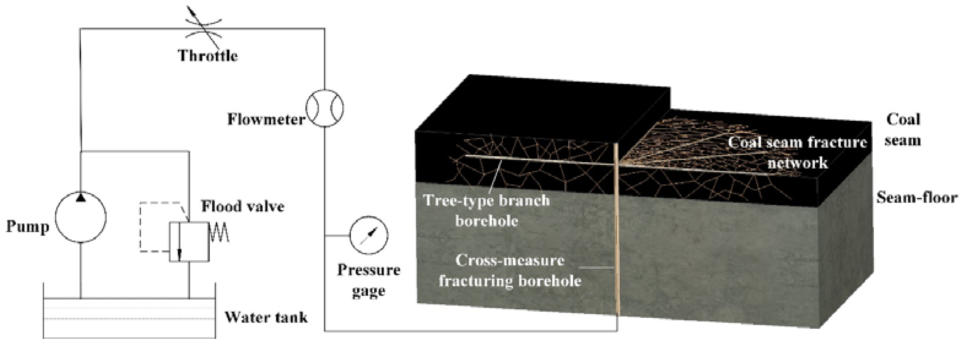
2.2. Tree-Type Hydraulic Fracturing System

The entire branched array system can be divided into a tree-type borehole generating system and hydraulic fracturing system. The borehole generating system includes, but is not limited to, the drill rig, drill pipe, pressing device, steering device, and self-advanced drilling systems [21]. The hydraulic fracturing system includes, but is not limited to, a pressurizing device, pressure and flow control systems and a hole-sealing device (Figure 2).

2.3. Processes of Tree-Type Hydraulic Fracturing

The fracturing process is divided into the tree-type borehole generating process and hydraulic fracturing process. The borehole generating process involves, first, drilling a cross-measure fracturing borehole into a coal seam from a rock roadway. The next step is to drill branching boreholes with a steering device by means of a self-advancing, high-pressure water jet drilling system. The length of the branching boreholes ranges from 10 to 20 m. The branching boreholes that result at the bottom of the cross-measure fracturing borehole are parallel to the coal seam, and are uniformly and radially distributed by the steering device. After the cross-measure fracturing borehole and tree-type branching boreholes are completed, the cross-measure fracturing borehole and hydraulic fracture are sealed.

3. Numerical Simulation of Crack Initiation and the Law of Extension

3.1. Numerical Analysis

The developmental status of cracks is the most important factor determining the gas drainage effect after fracturing. The developmental status of cracks can be evaluated by measuring the number of cracks, the length of cracks, and the total impact area of cracking. Rock failure process analysis of flow-stress-damage coupling analysis research system (RFPA2D-Flow) is capable of numerical simulation of coal seam fracturing and crack extension. It is also considered that the study of crack extension and developmental status is intuitive when using models of tree-type, branched hydraulic fracturing.

3.1.1. Introduction of Rock Failure Process Analysis (RFPA)

The RFPA2D-Flow is based on FEM and was developed by Dalian Mechanics Software Co. Ltd. in China. By introducing the heterogeneity of rock material properties into the model, RFPA2D can simulate nonlinear deformation of a quasi-brittle rock with an ideal elastic-brittle constitutive law for local material [22]. By extending Biot’s theory of consolidation to include stress effects on permeability, the following governing equations can be obtained [23,24]:
(a)
Balance equation:
σ i j x i j + X j = 0   ( i , j = 1 , 2 , 3 )
where σ i j is the total stress in the ij-plane and X j is the body force in the jth direction.
(b)
Geometrical equation:
ε i j = 1 2 ( u i , j + u j , i )   ε ν = ε 11 + ε 22 + ε 33
where ε i j is the strain and u i is the displacement in the ith direction.
(c)
Constitutive equation:
σ i j = σ i j α p δ i j = λ δ i j ε v + 2 G ε i j
where σ i j is the effective stress in the ij-plane, p is the pore pressure, α is the coefficient of pore-fluid pressure, λ is the Lame’ coefficient, G is the shear modulus, and δ i j is the Kronecker constant.
(d)
Seepage equation:
k 2 p = 1 Q p t α ε v t
where k is the coefficient of permeability and Q is the Biot constant.
(e)
Coupling equation:
k ( σ , p ) = ξ k i e β ( σ i j / 3 α p )
where k i is the initial coefficient of permeability, and ξ and β are material constants.
The above Equations (1)–(4) come from Biot’s theory of consolidation. Equation (5) in the coupling model is used to represent the influence of stress on permeability by assuming that the permeability and stress follow a negative exponential function.

3.1.2. Coupling Equation of Flow and Damage

When the stress of the element satisfies the strength criterion, the element begins to fail. In elastic damage mechanics, the elastic modulus of the element may degrade gradually as damage progresses, and the elastic modulus of the damaged element is defined as follows [25]:
E = ( 1 D ) E 0
where D is the damage variable, and E and E 0 are the elastic moduli of the damaged and undamaged elements, respectively.
When the element is under a tensile stress condition, the damage variable can be described as:
D = { 0 ( ε ε t 0 ) 1 σ t r / ( ε E 0 ) ( ε t u ε < ε t 0 ) 1 ( ε ε t u )
where σ t r is the residual tensile strength, ε t 0 is the elastic limit tensile strain, and ε t u is the maximum tensile strain.
In this case, the permeability k can be described as:
k = { k 0 e β ( σ 3 α p ) ( D = 0 ) ξ k 0 e β ( σ 3 α p ) ( 0 < D < 1 ) ξ k 0 e β ( σ 3 α p ) ( D = 1 )
where ξ is the damage factor of permeability, which reflects the increase in permeability that is induced by damage, and σ 3 is the minimum principal stress.
When the element is under a compressive stress condition, the damage variable can be described as:
D = { 0 ( ε < ε c 0 ) 1 σ c r / ( ε E 0 ) ( ε ε c 0 )
where σ c r is the residual compressive strength, and ε t 0 is the elastic limit compressive strain.
In this case, the permeability k can be described as:
k = { k 0 e β ( σ 1 α p ) ( D = 0 ) ξ k 0 e β ( σ 1 α p ) ( D > 0 )
where ξ is the damage factor of permeability, and σ 1 is the minimum principal stress.

3.1.3. Numerical Analysis Case-Study

To study the effects of the branched hydraulic fracturing technology, and the impacts of different forms of the branching, a simplified example of conventional cross-measure hydraulic fracturing in China is used to compare and contrast. Cross-measure hydraulic fracturing has only one cross-measure fracturing borehole, which can be simplified to a “zero-branched” borehole model. The tree-type model, however, may have many branches, but will be simplified to a two-branched model, a four-branched model and a six-branched model.
Throughout the fracturing process, the focus is on crack initiation and extension and thus, considering the large size of the numerical model, the large number of elements meshing and the finite computing power, the four different model forms are regarded as plane strain models, and are cut in the horizontal plane. Taking into account the need for numerical analysis, the horizontal stress is applied to the left, right and upper sides of the model, while the underside of the model is supported by simple constraints. The horizontal stress of the left and right sides is 20 MPa, and the upper side is 10 MPa. The pore pressure boundaries and pressure boundaries are the model boundaries. The water injection pressure acts upon the border of the excavation area inside the model where the initial pressure (P0) is 5 MPa and incremental pressure (P) applied in steps (e.g., Step 1, Step 2, etc.) is 0.5 MPa.

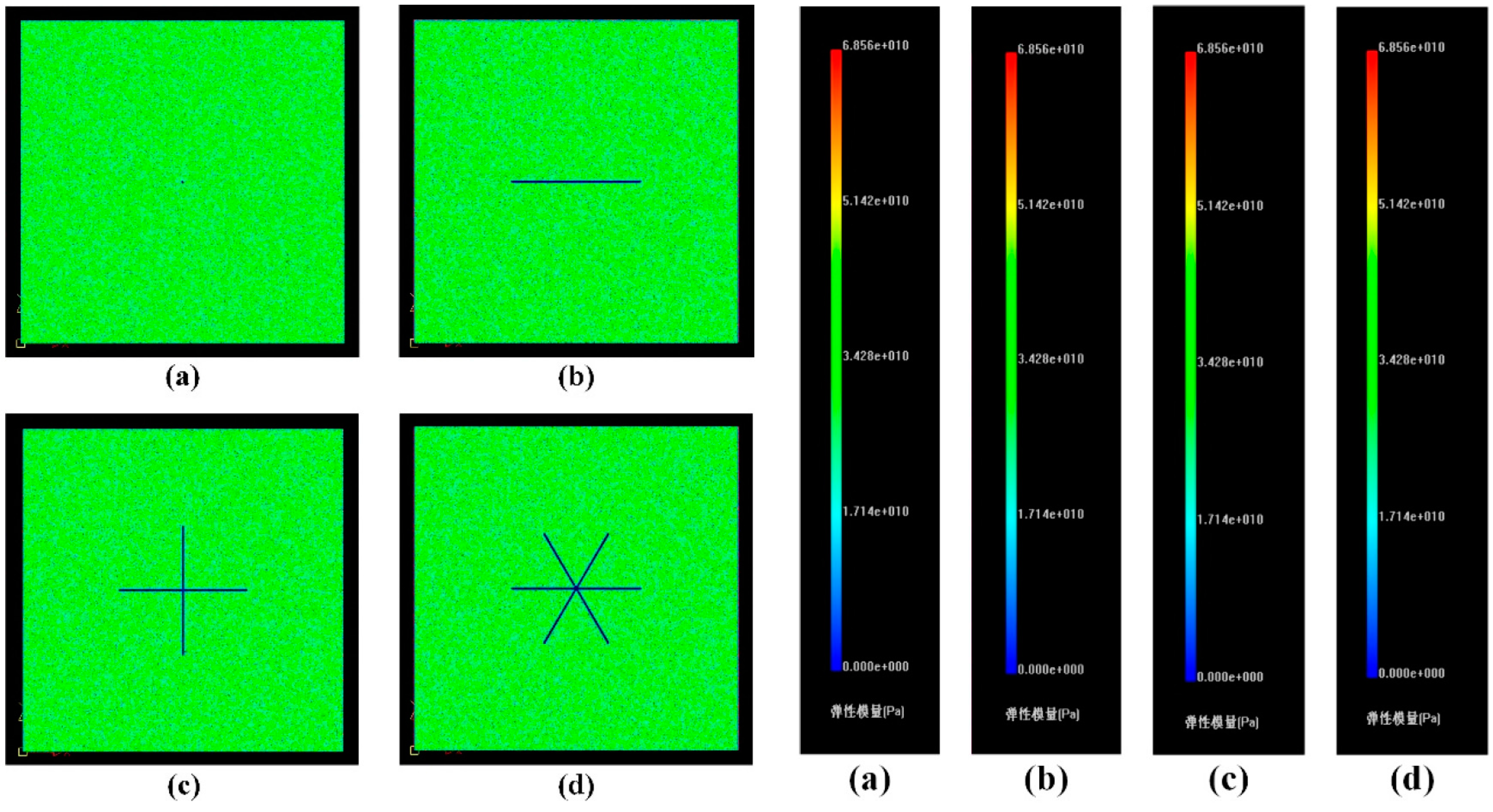
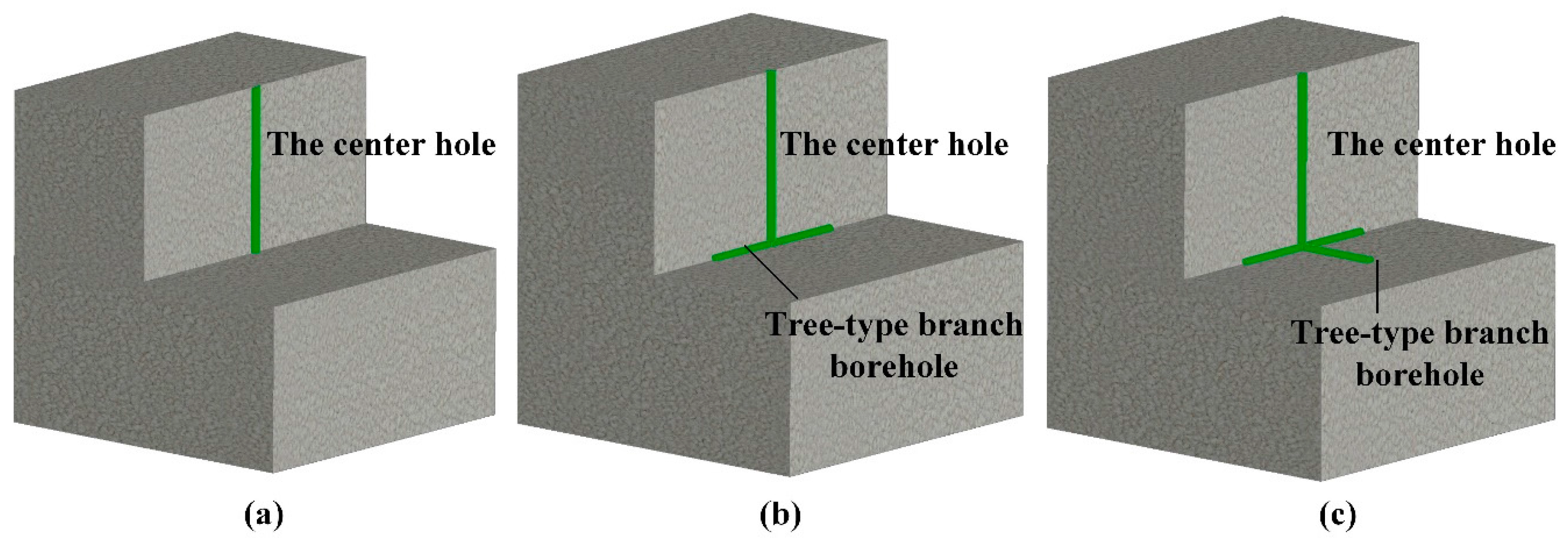
3.1.4. Numerical Analysis Model

To reduce the influence of the size effect on fracturing, the four models were each set as squares with side lengths of 100 m, divided into 500 × 500 = 250,000 cells, and basic mechanical parameters of the models are shown in Table 1. The zero-branched model (Figure 3) has an excavation circle of 0.4 m diameter in the middle of the grid as a pressure borehole. The two-, four- and six-branched models (Figure 3) have, respectively, excavations of combinations of one, two and three rectangles in the middle of the grid where each rectangle is 40 m × 0.4 m. The combinations are regarded as two, four and six multiples of 20-m-long branched boreholes, respectively.

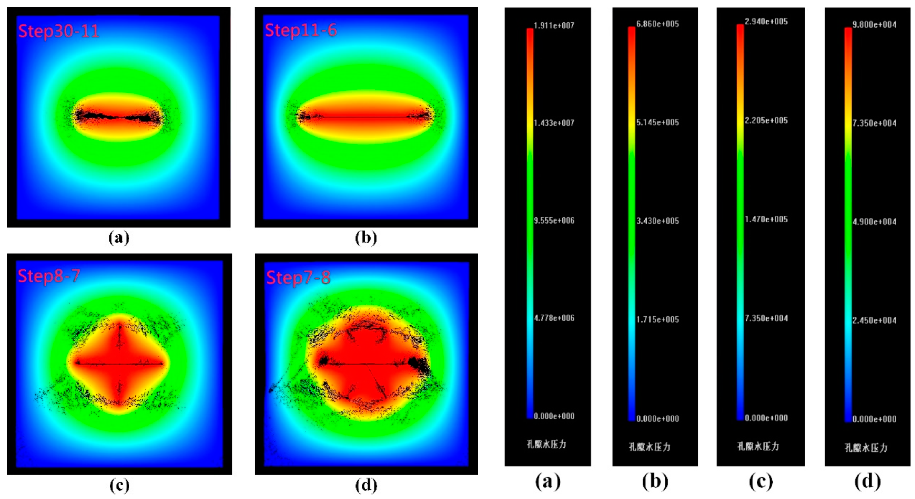
3.2. Results of Numerical Analysis

During numerical simulation, the zero-, two-, four- and six-branched borehole models cracked, respectively, in Step 30, Step 11, Step 8 and Step 7. This translates to respective initiation pressures of 20 MPa, 10.5 MPa, 9 MPa and 8.5 MPa. Compared with the initiation pressure of the zero-branched model, the two-, four- and six-branched borehole models had initiation pressures reduced by 47.5%, 55% and 57.5%, respectively (Figure 4). This indicates that the branched borehole arrays led to a measurable reduction in initiation pressure, most likely because of stress concentration and the destruction zone and plastic zone, resulting in an increased likelihood of cracking around the borehole.
It is evident from images of the seepage pore-water pressure fields (Figure 5) that different forms of branched borehole models yield differing pressure results. The zero- and two-branched models extend in a single direction while cracks initiate and multiply at the ends of four- and six-branched models. The cracks then extend to the adjacent branched boreholes and form a central fractured zone around the branched boreholes. Because the model is affected by the ground stress state, the cracks also tend to extend parallel to the maximum principal stress. With an increasing number of branched boreholes, there is an increase in crack-initiation locations, and improved connection between the branches. This leads to a more balanced fracture network and a decrease in “blank areas”. Overall, the simulation results show that a branched borehole array can reduce initiation pressure and improve the distribution of crack initiation and extension.

4. Additional Simulation Tests and the Law of Extension

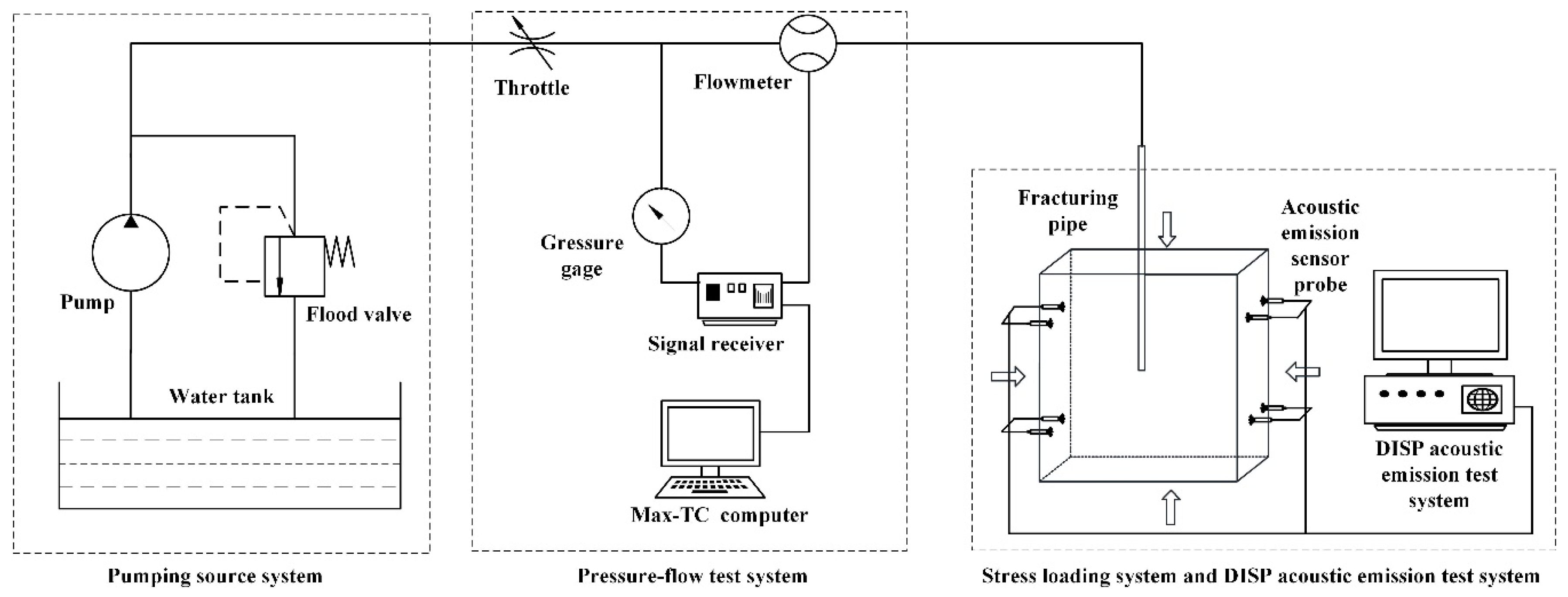
4.1. Experimental Device and Method

The experimental device is a true triaxial hydraulic fracturing simulation system. It consists of three parts: the pump source system (31.5 MPa, 20 L/min high-pressure pumps, manual control), pressure and flow testing system (i.e., flow and pressure gathering system) and a stress loading system (Figure 6).
Water is used as the hydraulic fracturing fluid in the test and yellow pigment is added as a tracer to express the form and distribution of cracks that result. The initial flow rate is 200 mm3/s. During the test, a digital signal processing (DiSP) acoustic emission (AE) positioning system is used to monitor the initiation and extension of cracks in the specimen. The specimens are split open after the fracturing test for further observations.
The purpose of this experiment is to study and contrast the impacts of different forms of branched borehole arrays on crack initiation and extension, so there is no need to simulate specific geostress loads. According to the world geostress change rule with depth, summarized by Hooke and Brown, and based on research on distribution of shallow crustal geostress in Mainland China [26], it is possible to quantify the relationship between various stresses. The relationship between mean horizontal terrestrial stress ( σ h , a v ) and perpendicular terrestrial stress ( σ v ) and that between the maximum main horizontal stress ( σ H ) and minimum main horizontal stress ( σ h ) are as follows:
{ σ h , a v / σ v = 0.8 1.2 σ h / σ H = 0.5 0.75
In accordance with Equation (11), the final value of σ v is 4 MPa, the final value of σ h is 6 MPa, and 10 MPa for σ H .

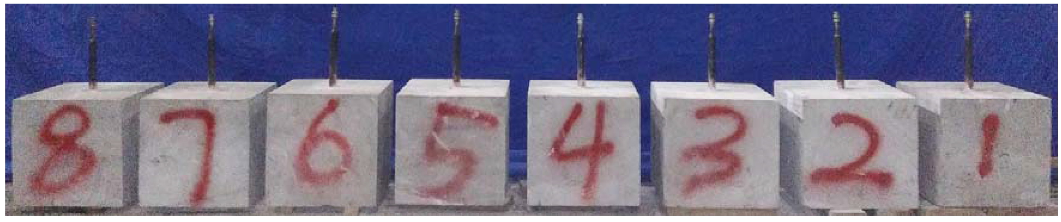
4.2. Specimen Processing

Based on the numerical analysis models, zero-, two- and four-branched borehole models were chosen as test models. The specimens were processed from homogeneous sandstone cut into cubes of 300 × 300 × 300 mm3. A diamond-tipped drill bit was used to drill a center hole from the upper surface into the cube, and then an abrasive water jet nozzle was inserted to erode the sandstone at the bottom of the center hole. The diameter of the center hole is 25 mm, and its length is 150 mm. For the different model specimens, the erosion holes were variously branched (zero, two or four branches). To ensure standardization of the length of erosion holes, the target distance, insertion distance and water pressure (10 MPa) were controlled for each specimen, as well as a standard abrasive concentration of 5% and erosion time of 20 s.
The zero-branched borehole model evidently does not require erosion, but the two-branched model requires two branches located at the bottom of the center hole. This is achieved by eroding two diverging branches, 180° apart with individual lengths of 70 mm (Figure 7). The four-branched model is simply a modification of this, with 70-mm-long branches eroded at 90° to each other.
After erosion, the center hole and branched boreholes are cleaned, and then a high-strength AB glue cement is used to cement the fracturing pipe into the center hole [27]. The AB glue is used to cement rebar and concrete in the construction industry. The fracturing pipe is a seamless steel pipe with an inner diameter of 6 mm and outer diameter of 20 mm. To prevent the glue plugging the branched boreholes and fracturing pipe, medical tape was wound around the fracturing pipe 30 mm from the base of the pipe and the AB glue is then used to fill the remaining gap. Once the glue was set, the upper surfaces of the specimens were polished smooth. The completed specimens are shown in Figure 8. Basic mechanical parameters of the sandstone, determined using an MTS hydraulic servo system, the tensile strength is 4.1 MPa, the compressive strength is 56.9 MPa, the elasticity modulus is 36 GPa, and the Poisson’s ratio is 0.24.

4.3. Test Results

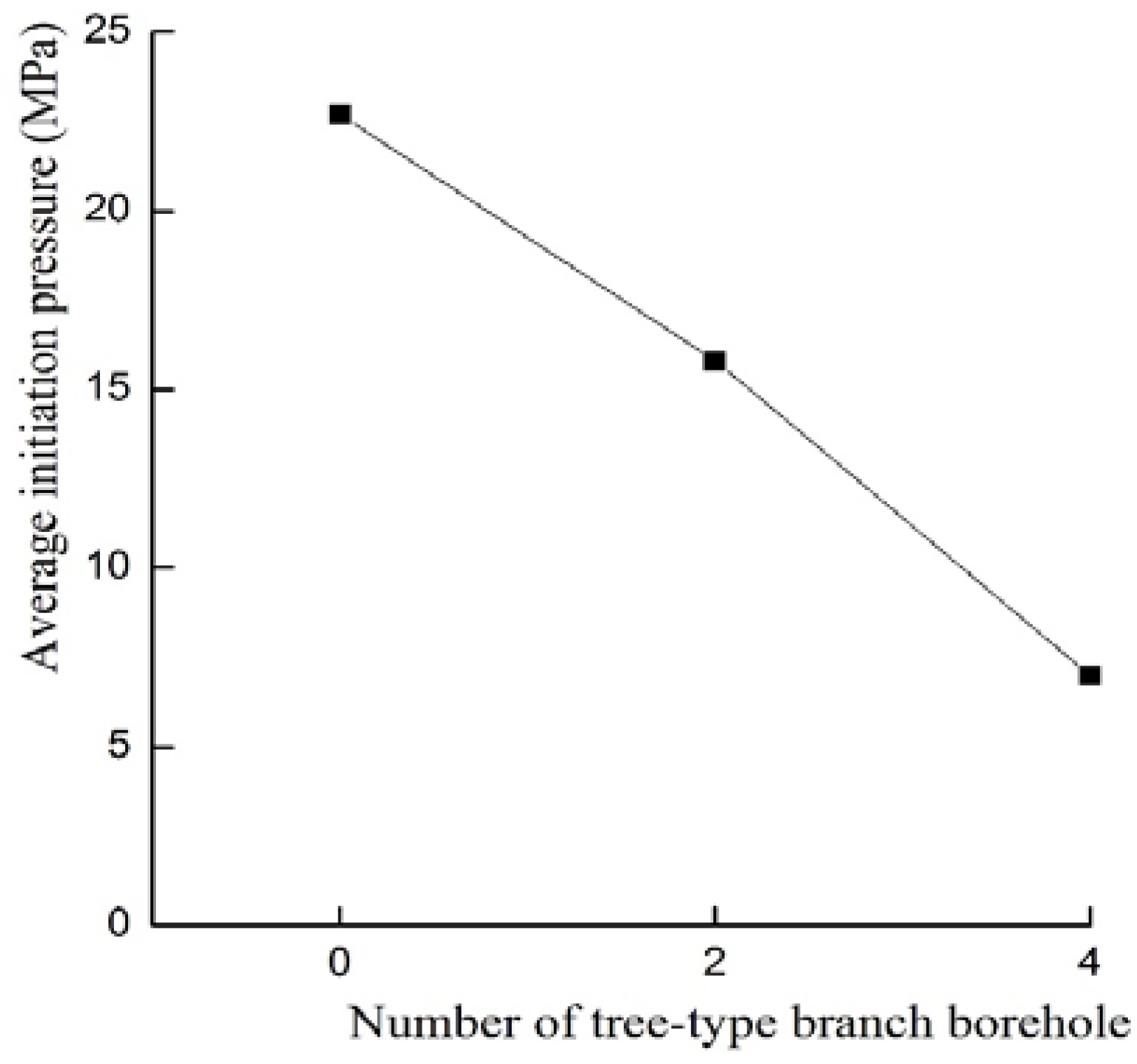
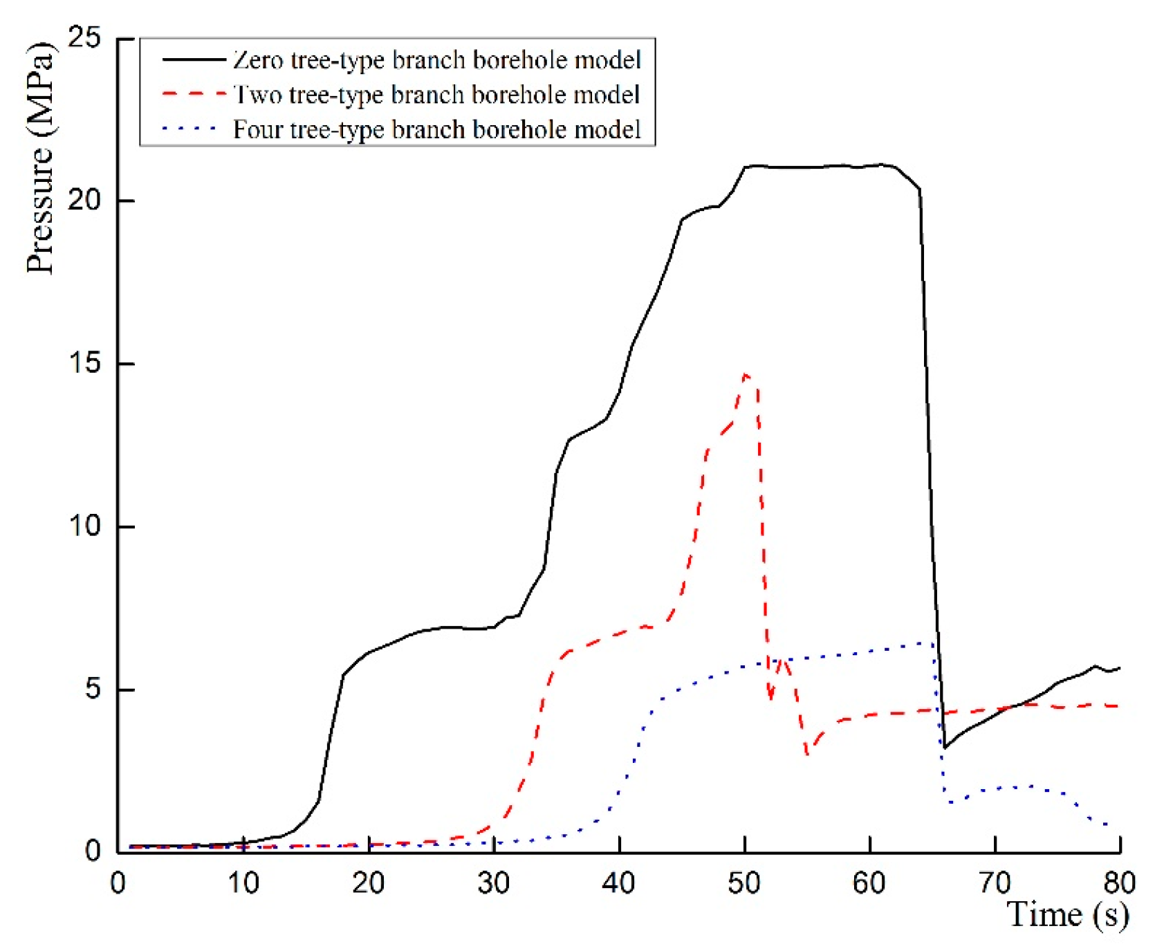
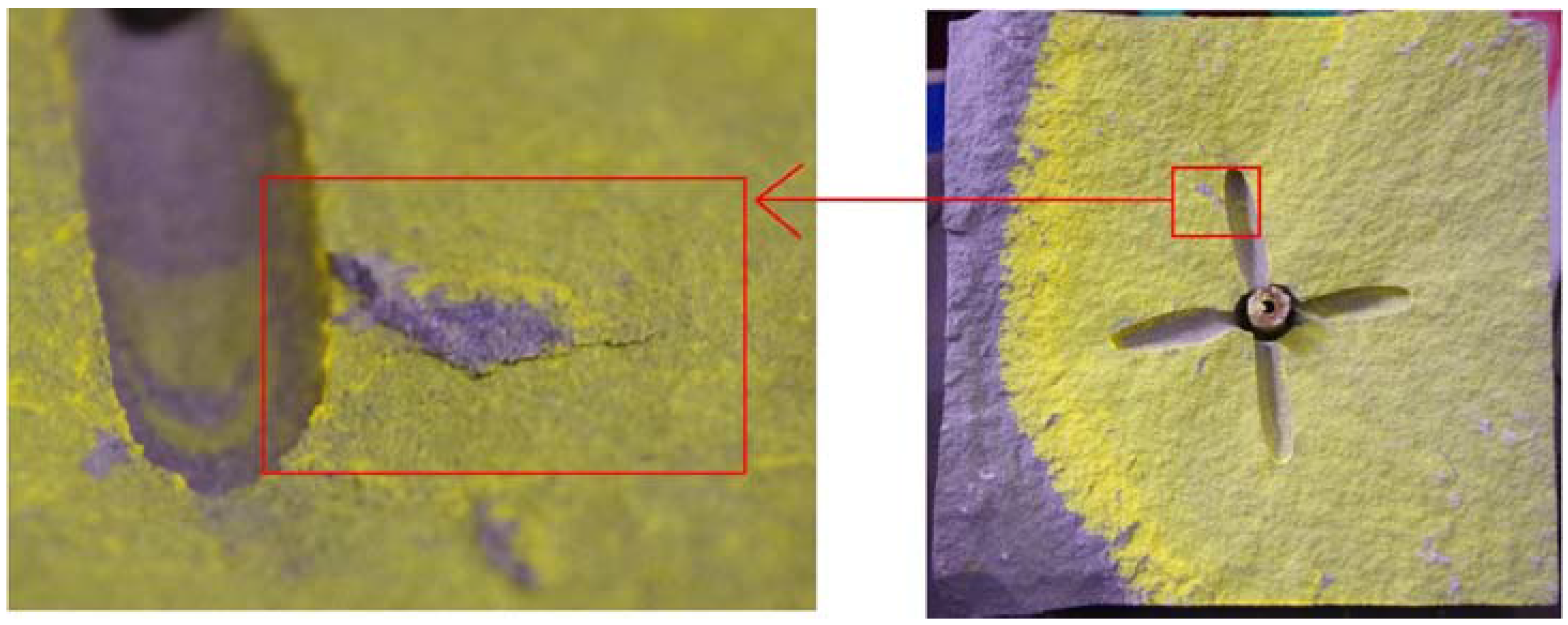
4.3.1. Crack Initiation

During the test, it was found that the initiation pressures of different forms of branched borehole models were significantly different. The zero-branched model has the highest initiation pressure, with an average value of 22.7 MPa. The two-branched model has an average initiation pressure of 15.8 MPa; this is a 30.4% reduction. The initiation pressure of the four-branched model has the lowest value, with an average value of 7.0 MPa (a 69.2% reduction compared with the zero-branched model). Pressure vs. time curves of the different model forms are shown in Figure 9. By plotting the number of branches against the initiation pressure (Figure 10), it is evident that a relationship exists, such that with an increase in branched boreholes, there is a reduction in initiation pressure.
To monitor crack initiation and extension in real time, eight DiSP AE sensors were evenly distributed on two sides of each of the specimens; that is, four sensor probes on each side arranged at a distance of 50 mm from each edge of the specimen (Figure 6).
Compared with the distribution of AE events of the different specimens, and taking account of the results of numerical simulation, it is found that the different model forms develop cracks in different positions. Based on the sequence of AE events, it is found that the initiation location of the zero-branched model is at the bottom of the center hole. The crack initiation location in the two- and four-branched model is mainly at the ends of the branched boreholes, most likely because the tree-type, branched boreholes produce a stress concentration and thus increase the likelihood of cracking.
The average AE event values of the zero-branched model, two-branched model and four-branched model are 18, 20 and 35, respectively. This is because the initiation location of the zero-branched model occurs earlier, at the base of the center hole, while in the branched models there are multiple events (at the end of each branched borehole) that occur somewhat later. However, the specimen size is limited, and the sandstone is brittle, so shortly after crack initiation at the ends of branched boreholes, they extend to adjacent boreholes and thus develop a fracture surface. The specimen cannot form the crack network as seen in the numerical simulation. As the evidence of crack network, some secondary cracks can still be found in the specimen (Figure 11).
Taking into account the results of the numerical simulation and similar simulation testing, it is considered that the branched borehole array clearly reduces the fracture initiation pressure and controls crack initiation and extension. The branched borehole array tends to induce crack initiation at most ends of the branches, rather than simply at the base of the center hole, as is the case for the zero-branched model.

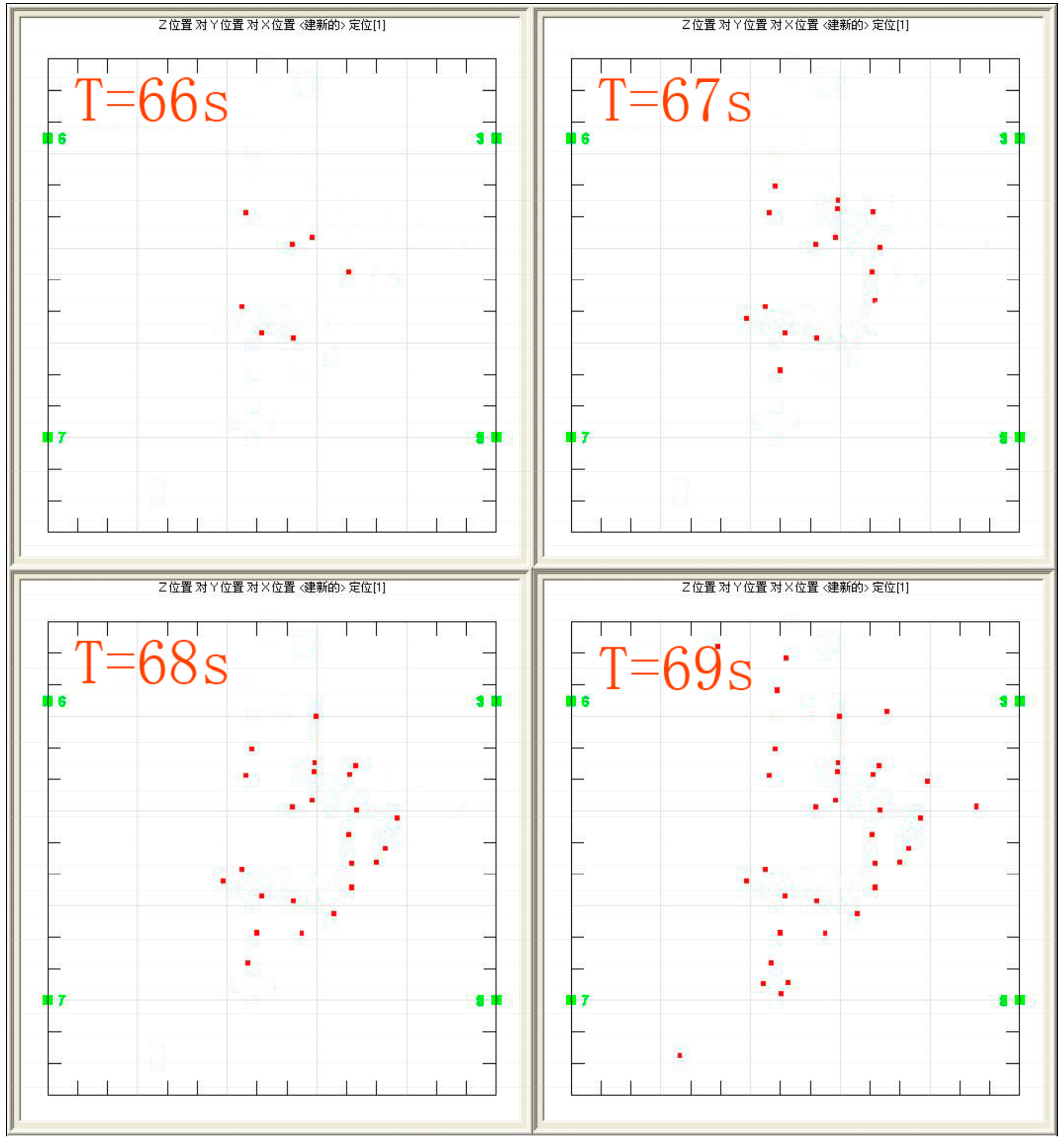
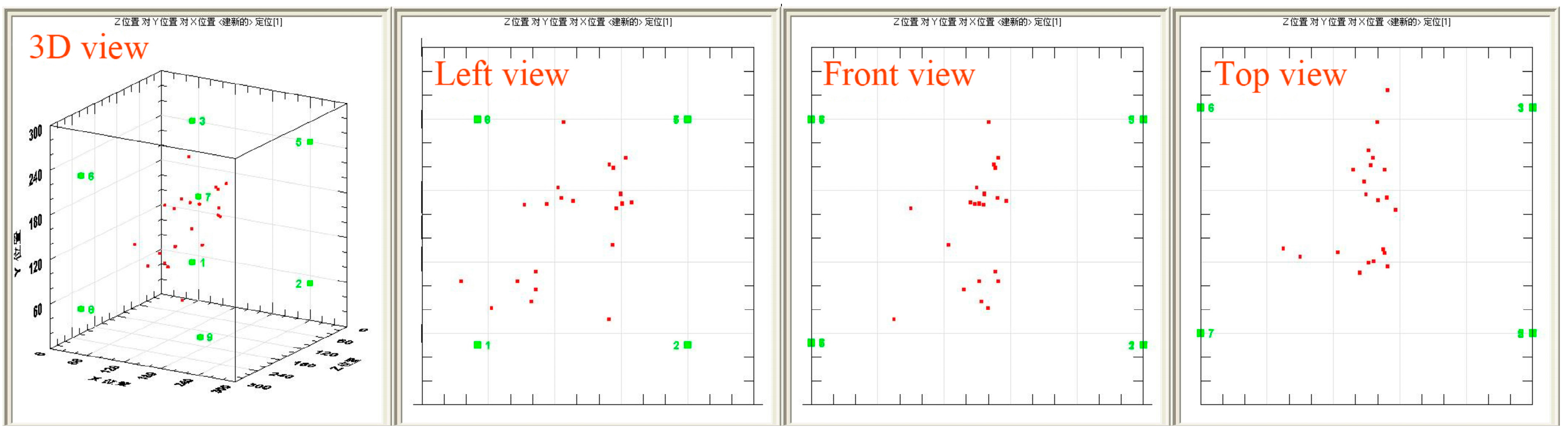
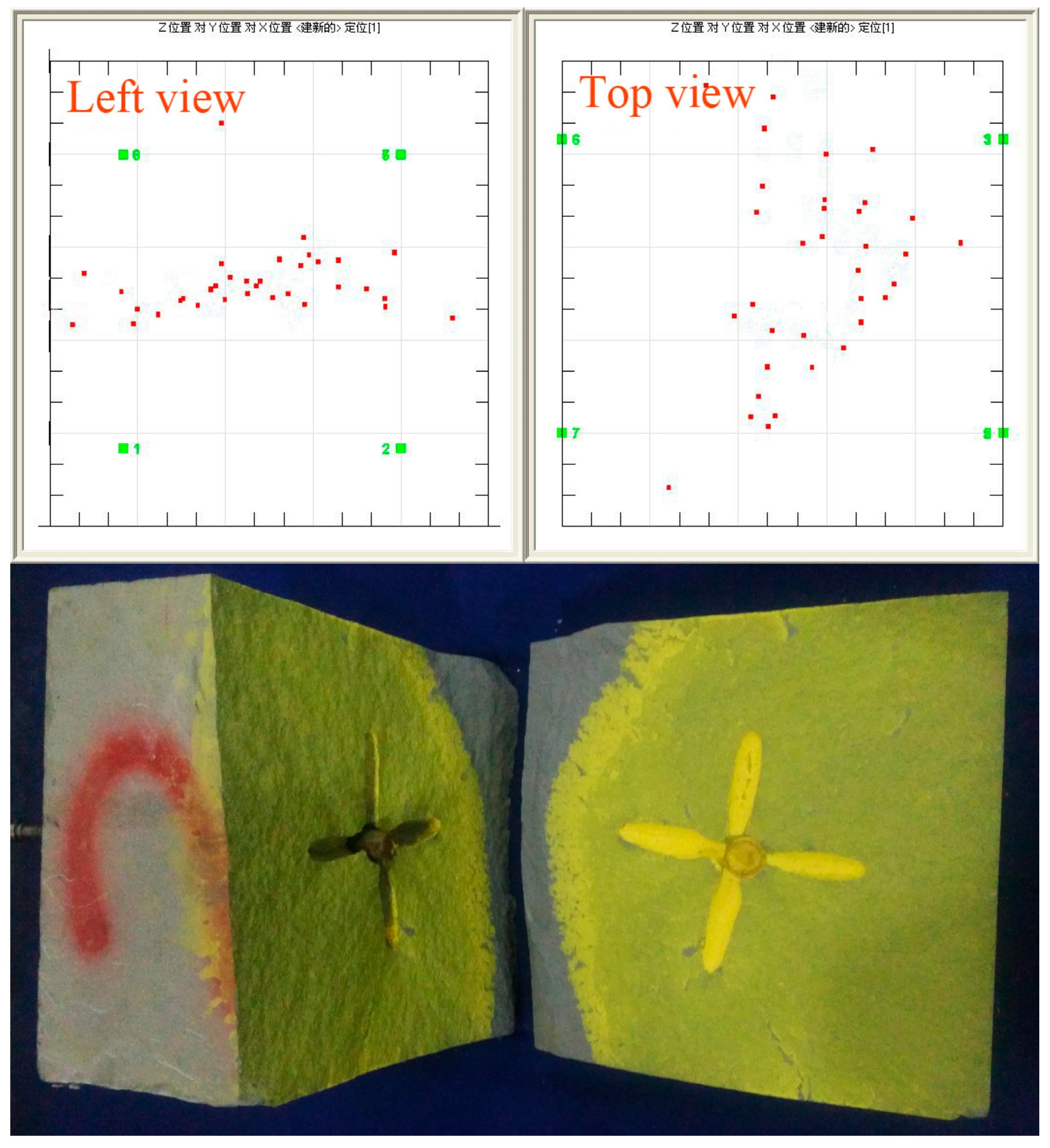
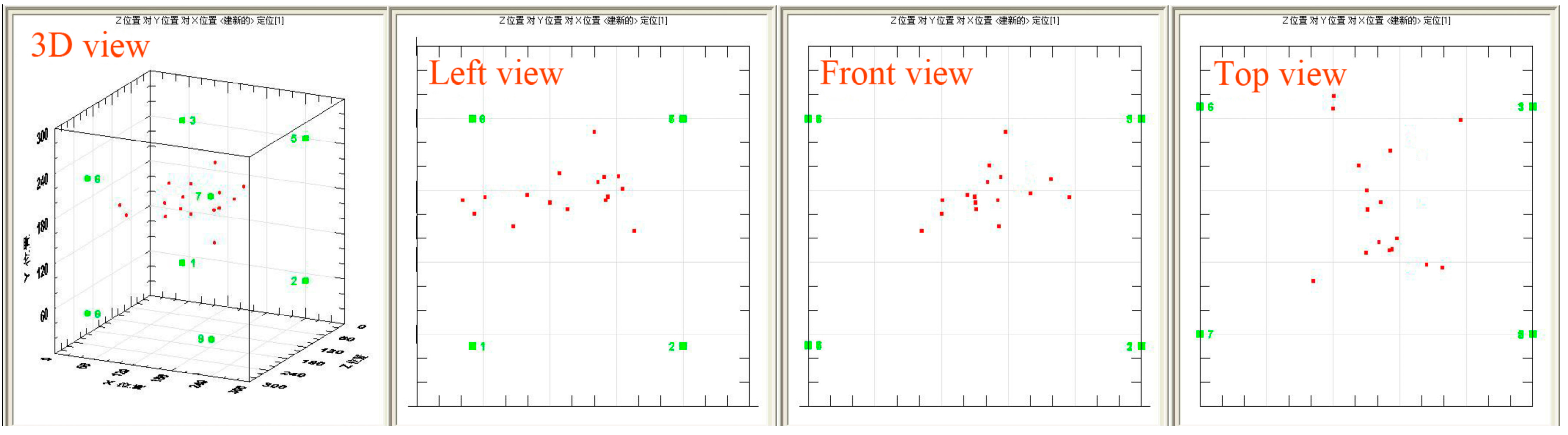
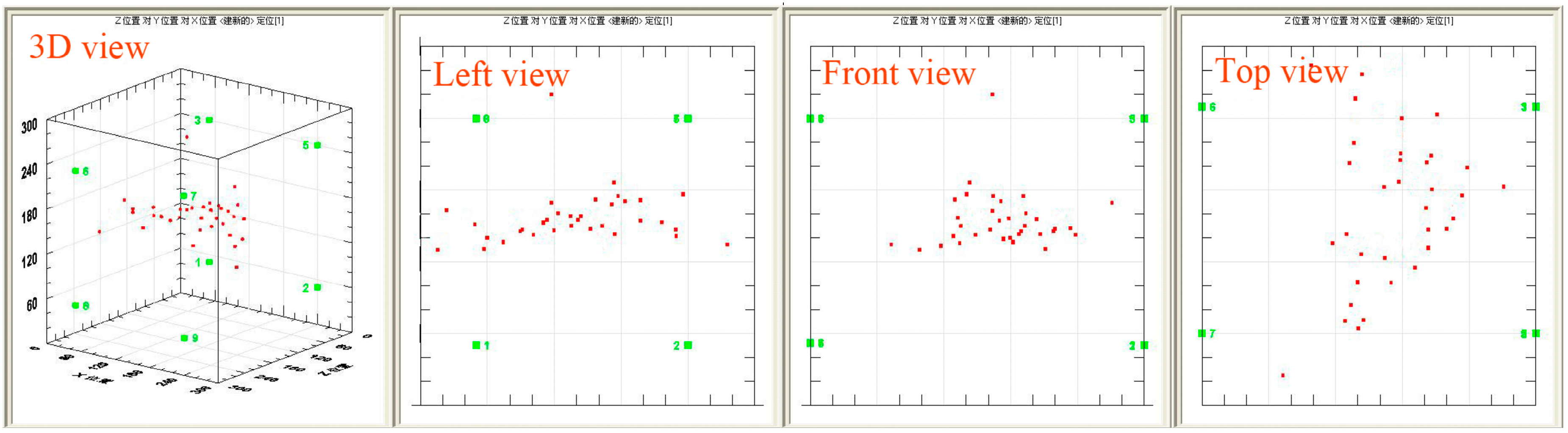
4.3.2. Crack Extension

Comparison of the AE event distribution and the sandstone specimens (Figure 12) shows that the location and sequence of AE events are essentially coincident with the locations of crack initiation and extension, as well as the shape of the main crack. The fracturing process monitored by the DiSP AE system is also coincident with the processes of numerical simulation, indicating that the AE event distribution is valuable in quantifying the distribution and orientation of the fracturing.
AE events tend to occur in the middle of the specimen first and extend outward as fracturing continues until it ceases. For example, the No. 3 specimen (four-branched, Figure 13) begins to crack at 66 s, and AE events occur first around the branched boreholes. The specimen is evidently undergoing cracking at the ends of the branched boreholes and AE events continue to occur in the middle of the adjacent boreholes and periphery at 67 s and 68 s. This suggests that cracks are connecting each adjacent branched borehole and extending outward. AE events continue at 72 s as cracks continue extending outward, forming a final fracture surface.
Figure 14, Figure 15 and Figure 16 show the distribution of AE events in different specimens. By comparing the distributions, it is found that the extension direction of different model forms is variable. The zero-branched and two-branched specimens mainly have crack extension along the direction of maximum principal stress. The four-branched specimen, however, has crack extension along the direction of adjacent branched boreholes, while still somewhat influenced by the maximum principal stress.
During hydraulic fracturing, crack initiation (around the ends of branched boreholes, for example) is also related to the tendency of cracks develop to a high pore-water pressure [20]. That is, the high pore-water pressure of adjacent branched boreholes will tend to attract crack development, allowing for the extension of cracks between such branches. Nevertheless, it is the overall interaction of adjacent branched boreholes, pore-water pressure and in-situ stress that leads to crack extension between adjacent branched boreholes, and ultimately a fracture surface.
Based on the results of both numerical and similar simulation testing, it can be concluded that the branched borehole arrays used for hydraulic fracturing promote and control crack initiation and guide crack extension, even in terms of orientation as described above. With the increase in branched boreholes, there is an increase in crack connection, and the overall coal crack network will become larger and better distributed, bearing in mind that cracking will also produce secondary cracks to the roof and floor. In engineering applications, the coal crack network will be more uniformly distributed, reducing the occurrence of “blank areas” and substantially increasing the coal seam permeability. This method is also likely to reduce damage to the roof and floor because of the tendency of cracking to occur in the plane of the coal seam (fewer cracks initiate and extend to the roof and floor then conventional cross-measure hydraulic fracturing), and the lower initiation pressure (lower initiation pressure can reduce the deformation of coal seam and rock), and thus it should have a positive effect on subsequent excavation and support work.

5. Conclusions

Based on the study of different forms of tree-type, branched borehole hydraulic fracturing models by means of numerical simulation and similar simulation testing, the following conclusions can be made:
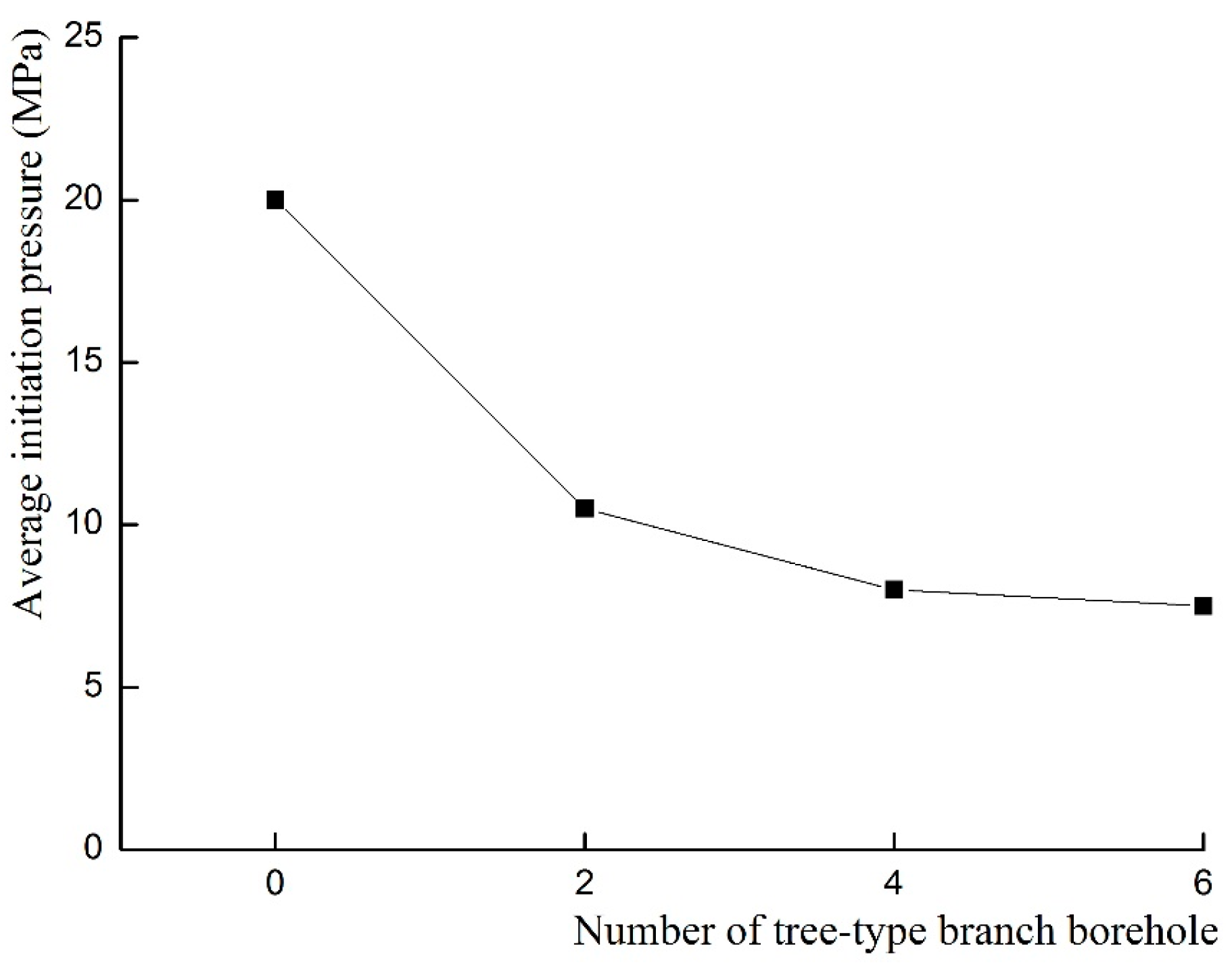
  • Tree-type, branched borehole arrays reduce initiation pressure required for hydraulic fracturing. With an increase in the number of branches in the borehole, there is a measurable decrease in the initiation pressure. The model with four branches reduced the initiation pressure by 69%.
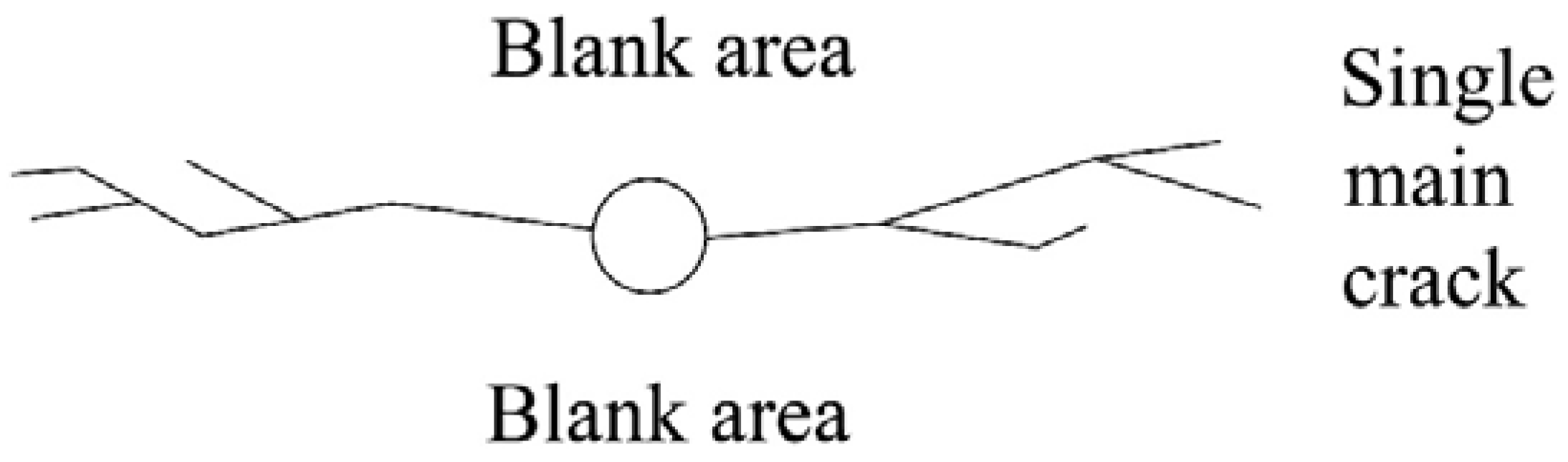
  • The tree-type borehole array initiates cracks from the bottom of the branched boreholes, with the cracks extending along the direction of the adjacent borehole array. In general, the more branches in the borehole array, the larger the resulting fracture network. In addition, the more balanced the distribution of the resulting fracture network, the better the fracturing effect becomes.
  • As a permeability improvement technology in underground coal mining, this branched tree-type borehole array has the advantage of reducing initiation pressure, controlling crack initiation and extension, enhancing fracturing effect and reducing damage to the roof and floor of the mine.

Acknowledgments

This study was funded by the National Science and Technology Major Projects of China under Contract No. 2011ZX05065, the National Natural Science Foundation of China (No. 51374258), and the Program for Changjiang Scholars and Innovative Research Team in University of China (No. IRT13043).

Author Contributions

Yiyu Lu, Shaojie Zuo and Zhaolong Ge all contributed to designing the simulations and writing the paper; and Songqiang Xiao and Yugang Cheng performed numerical and similar simulations.

Conflicts of Interest

The authors declare no conflict of interest.

References

  1. Li, S.; Tang, D.Z. A comparative study of the characteristics of coalbed methane reservoirs in the Zhina region, Guizhou Province and the Southern Qinshui Basin, Shanxi Province, China. Int. J. Oil Gas Coal Technol. 2014, 7, 95–113. [Google Scholar] [CrossRef]
  2. Karacan, C.Ö.; Ruiz, F.A.; Cotè, M.; Phipps, S. Coal mine methane: A review of capture and utilization practices with benefits to mining safety and to greenhouse gas reduction. Int. J. Coal Geol. 2011, 86, 121–156. [Google Scholar] [CrossRef]
  3. Wang, F.T.; Ren, T.; Tu, S.H.; Hungerford, F.; Aziz, N. Implementation of underground longhole directional drilling technology for greenhouse gas mitigation in Chinese coal mines. Int. J. Greenhouse Gas Control 2012, 11, 290–303. [Google Scholar] [CrossRef]
  4. Gao, Y.B.; Lin, B.Q.; Yang, W.; Li, Z.W.; Pang, Y.; Li, H. Drilling large diameter cross-measure boreholes to improve gas drainage in highly gassy soft coal seams. J. Nat. Gas Sci. Eng. 2015, 26, 193–204. [Google Scholar] [CrossRef]
  5. Wanniarachchi, W.A.M.; Ranjith, P.G.; Perera, M.S.A.; Lashin, A.; Al Arifi, N.; Li, J.C. Current opinions on foam-based hydro-fracturing in deep geological reservoirs. Geomech. Geophys. Geo-Energy Geo-Resour. 2015, 1, 121–134. [Google Scholar] [CrossRef]
  6. Lu, Y.Y.; Yang, F.; Ge, Z.Z.; Wang, S.Q.; Wang, Q. The influence of viscoelastic surfactant fracturing fluids on gas desorption in soft seams. J. Nat. Gas Sci. Eng. 2015, 27, 1649–1656. [Google Scholar] [CrossRef]
  7. Heo, W.; Lee, W.; Lee, D.S. Hydraulic fracturing design for coalbed methane in Barito basin, Indonesia. Geosyst. Eng. 2015, 18, 1–12. [Google Scholar] [CrossRef]
  8. Li, Q.G.; Lin, B.Q.; Zhai, C. A new technique for preventing and controlling coal and gas outburst hazard with pulse hydraulic fracturing: A case study in Yuwu coal mine, China. Nat. Hazards 2015, 75, 2931–2946. [Google Scholar] [CrossRef]
  9. Zhang, X.; Jeffrey, R.G.; Bunger, A.P.; Thiercelin, M. Initiation and growth of a hydraulic fracture from a circular wellbore. Int. J. Rock Mech. Min. Sci. 2011, 48, 984–995. [Google Scholar] [CrossRef]
  10. Wang, P.; Mao, X.B.; Du, C.Z.; Sun, F.J. Study on the propagation mechanism of the crack for the borehole hydraulic fracturing in coal seam. J. Min. Saf. Eng. 2009, 26, 31–35. (In Chinese) [Google Scholar]
  11. Lu, Y.Y.; Cheng, L.; Ge, Z.L.; Xia, B.W.; Li, Q.; Chen, J.F. Analysis on the initial cracking parameters of cross-measure hydraulic fracture in underground coal mines. Energies 2015, 8, 6977–6994. [Google Scholar] [CrossRef]
  12. Olovyanny, A.G. Mathematical modeling of hydraulic fracturing in coal seams. J. Min. Sci. 2005, 41, 61–67. [Google Scholar] [CrossRef]
  13. Song, C.P.; Lu, Y.Y.; Xia, B.W.; Hu, K. Effects of natural fractures on hydraulic fractures propagation of coal seams. J. Northeast. Univ. 2014, 35, 756–760. (In Chinese) [Google Scholar]
  14. Lin, B.Q.; Liu, T.; Zou, Q.L.; Zhu, C.J.; Yan, F.Z.; Zhang, Z. Crack propagation patterns and energy evolution rules of coal within slotting disturbed zone under various lateral pressure coefficients. Arab. J. Geosci. 2015, 8, 6643–6654. [Google Scholar]
  15. Rbeawi, S.A.; Tiab, D. Pressure behaviours and flow regimes of a horizontal well with multiple inclined hydraulic fractures. Int. J. Oil Gas Coal Technol. 2013, 6, 207–241. [Google Scholar] [CrossRef]
  16. Zhu, H.Y.; Deng, J.G.; Jin, X.H.; Hu, L.B.; Luo, B. Hydraulic fracture initiation and propagation from wellbore with oriented perforation. Rock Mech. Rock Eng. 2015, 48, 585–601. [Google Scholar] [CrossRef]
  17. Li, Z.C.; Li, L.C.; Tang, C.A. Numerical analysis on hydraulic fracture initiation and penetration characteristics in directionally perforated horizontal wells. Oil Gas Geol. 2015, 36, 504–509. (In Chinese) [Google Scholar]
  18. Chen, Z.; Xue, C.J.; Jiang, T.X.; Qin, Y.M. Proposals for the application of fracturing by stimulated reservoir volume (SRV) in shale gas wells in China. Nat. Gas Ind. 2010, 30, 30–32. (In Chinese) [Google Scholar]
  19. Mayerhofer, M.; Lolon, E.; Warpinski, N.; Cipolla, C.; Walser, D.; Rightmire, C. What is stimulated reservoir volume? SPE Prod. Oper. 2010, 25, 89–98. [Google Scholar] [CrossRef]
  20. Bruno, M.S.; Nakagawa, F.M. Pore pressure influence on tensile fracture propagation in sedimentary rock. Int. J. Rock Mech. Min. Sci. Geomech. Abstr. 1991, 28, 261–273. [Google Scholar] [CrossRef]
  21. Lu, Y.Y.; Zhou, Z.; Ge, Z.L.; Zhang, X.W.; Li, Q. Research on and design of a self-propelled nozzle for the tree-type drilling technique in underground coal mines. Energies 2015, 8, 14260–14271. [Google Scholar] [CrossRef]
  22. Tang, C.A. Numerical simulation of progressive rock failure and associated seismicity. Int. J. Rock Mech. Min. Sci. 1997, 34, 249–261. [Google Scholar] [CrossRef]
  23. Tang, C.A.; Tham, L.G.; Lee, P.K.K.; Yang, T.H.; Li, L.C. Coupled analysis of flow, stress and damage (FSD) in rock failure. Int. J. Rock Mech. Min. Sci. 2002, 39, 477–489. [Google Scholar] [CrossRef]
  24. Yang, T.H.; Tham, L.G.; Tang, C.A.; Liang, Z.Z.; Tsui, Y. Influence of heterogeneity of mechanical properties on hydraulic fracturing in permeable rocks. Rock Mech. Rock Eng. 2004, 37, 251–275. [Google Scholar] [CrossRef]
  25. Zhang, H.Q.; He, Y.N.; Tang, C.A.; Ahmad, B.; Han, L.J. Application of an improved flow-stress-damage model to the criticality assessment of water inrush in a mine: A case study. Rock Mech. Rock Eng. 2009, 42, 911–930. [Google Scholar] [CrossRef]
  26. Jing, F.; Sheng, Q.; Zhang, Y.H.; Luo, C.W.; Liu, Y.K. Research on distribution rule of shallow crustal geostress in China mainland. Trans. Am. Math. Soc. 2007, 26, 2056–2062. [Google Scholar]
  27. Ge, Z.Z.; Mei, X.D.; Lu, Y.Y.; Xia, B.W.; Chen, J.F. Mechanical model and test study of sealed drilling for hydraulic fracturing in underground coal mines. Rock Soil Mech. 2014, 35, 1097–1103. (In Chinese) [Google Scholar]
Figure 1. “Blank area” resulting from a single main crack propagation caused by ineffective cross-measure hydraulic fracturing.
Energies 09 00514 g001
Figure 2. Schematic diagram showing the layout and implementation of the tree-type hydraulic fracturing system.
Energies 09 00514 g002
Figure 3. Four kinds of tree-type hydraulic fracturing models, left side are the models and right side are the legends; (ad) they are zero-branched, two-branched, four-branched and six-branched.
Energies 09 00514 g003
Figure 4. Average initiation pressures as a function of the number of branches in the tree-type borehole arrays in numerical simulation.
Energies 09 00514 g004
Figure 5. Models of the seepage pore-water pressure fields of four kinds of tree hydraulic fracturing, left side are the models and right side are the legends; (ad) they are zero-branched, two-branched, four-branched and six-branched.
Energies 09 00514 g005
Figure 6. Schematic diagram of the hydraulic fracturing system model employed in the experimental study.
Energies 09 00514 g006
Figure 7. Different forms of tree-type branched borehole models: (a) zero-branched model; (b) two-branched model; and (c) four-branched model.
Energies 09 00514 g007
Figure 8. Completed sandstone specimens ready for hydraulic fracturing testing.
Energies 09 00514 g008
Figure 9. Time–pressure curves of different experimental models, illustrating the decrease in initiation pressure with increasing branches of the tree-type borehole array.
Energies 09 00514 g009
Figure 10. Average initiation pressures as a function of the number of branches in the tree-type borehole arrays in experimental test.
Energies 09 00514 g010
Figure 11. The details of secondary crack in four-branched borehole model, and positions in the specimen.
Energies 09 00514 g011
Figure 12. Comparison of AE events (left view and top view) in terms of spatial orientation, and fracture positions in the specimen.
Energies 09 00514 g012
Figure 13. Top views of acoustic emission events in the No. 3 specimen at 66 s, 67 s, 68 s and 69 s.
Energies 09 00514 g013
Figure 14. Spatial arrangement of acoustic emission events in the zero tree-type branch borehole hydraulic fracturing model.
Energies 09 00514 g014
Figure 15. Spatial arrangement of acoustic emission events in the two-branched tree-type borehole hydraulic fracturing model.
Energies 09 00514 g015
Figure 16. Spatial arrangement of acoustic emission events in the four-branched tree-type borehole hydraulic fracturing model.
Energies 09 00514 g016
Table 1. Basic mechanical parameters of the hydraulic fracturing models.
Basic Mechanical ParametersValue
Heterogeneity degree3
Elasticity modulus/GPa36
Internal friction angle/°30
Compressive strength/MPa60
Ratio of tensile and compressive10
Residual strength coefficients0.1
Pore-water pressure coefficient1
Osmotic coefficient/(m/d)1
Poisson‘s ratio0.15
Porosity0.1

