1. Introduction
The increasing penetration of dispersed energy resources (DERs) in distribution systems has improved microgrids’ implementation. The concept of the microgrid [
1,
2] includes the operation and control scheme, voltage and power regulation and energy management. At the beginning, AC microgrids were evolved, as the conventional power systems were dominated by the AC form. However, power generations from various DERs, such as photovoltaic systems, are DC power, so are modern electrical loads and energy storage systems. Those DC technologies are integrated with the existing AC systems through converters, which would expend more component costs and increase power losses. Moreover, it would add more power quality problems. According to those issues, DC microgrids, which are considered feasible to be implemented for commercial facilities [
3], are proposed as a better alternative for DERs. DC microgrids also offer more technical and economic benefits compared to AC microgrids [
4]. Since the utilization of AC power is still required, the integration of AC and DC microgrids is proposed, and this emerges the concept of hybrid AC/DC microgrids [
5,
6].
Control of microgrids becomes a critical issue for ensuring reliable operation of the microgrid. A variety of research has been conducted particularly on the subject of the control system and power management in order to improve the system stability [
7]. Each AC and DC microgrid has different hierarchical controls, but those could be generalize into three levels in reference to the hierarchical control standard of international society of automation (ISA)-95: (1) the primary control is based on the droop method, including an output-impedance virtual loop; (2) the secondary control allows the restoration of the deviations produced by the primary control; and (3) the tertiary control manages the power flow between the microgrid (MG) and the external electrical distribution system [
8].
In hybrid AC/DC microgrids, AC and DC buses are connected through interlink AC/DC bidirectional converters (ICs). The IC should be able to control and manage power properly in both operating mode, grid-connected mode and stand-alone mode [
9,
10]. Operating the microgrid in stand-alone mode would lead to more challenges, particularly when the imbalance of generation and consumption happen because of flexible load and DERs. Various droop control methods have been proposed to maintain the system stability by sharing power between AC and DC subgrids, as in [
11]. Incorporating an energy storage system into the IC will improve its control performance; meanwhile, DC link capacitors support the voltage regulation, as in [
12].
The contribution of this paper is proposing a coordination control strategy of IC to maintain secure operation of the microgrid system in terms of frequency and voltage regulation. It is assumed that a battery energy storage system (BESS) is installed in the DC microgrid for voltage support of the corresponding bus by charging or discharging, controlled by a DC/DC bidirectional converter. When the microgrid gets into the stand-alone mode, the BESS can provide an amount of power for the weak portion of the microgrid through the IC. However, active power support cannot be sustained because of the limitation of the state of charge (SOC) level of BESS. The IC controller needs to include the method to deal with the physical limits of the SOC of the BESS. In this circumstance, the weak portion of the microgrid might experience the severe degradation of system security. The last countermeasure that can be adopted is load shedding for secure operation, and the IC controller also needs to take into account the load shedding scheme. The proposed coordination control strategy between the IC and BESS converters can facilitate a smooth transition of the power transfer between AC and DC subgrids in stand-alone mode for secure operation, using the available resources and the last resort action of load shedding within the feasible operational region of BESS.
2. Hybrid AC/DC Microgrid Model
2.1. System Configuration
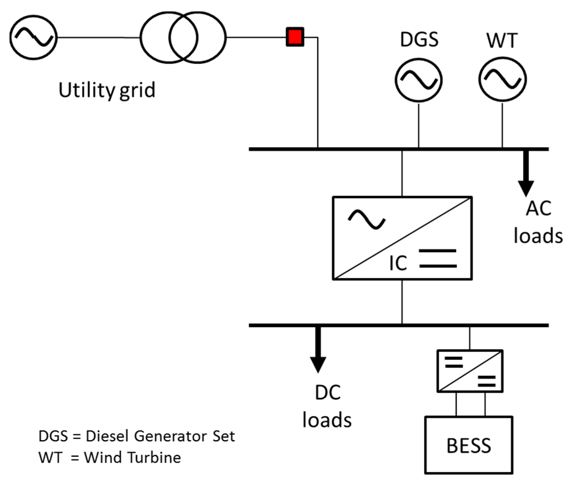
A simple model of a hybrid AC/DC microgrid is illustrated as in
Figure 1. In the AC microgrid, the power sources are from a 60-kilo volt ampere (kVA) diesel generator set and a 30-kW wind turbine with doubly-fed induction generator (DFIG). The AC load is composed of static loads and an induction motor with a total of 100 kW and 25 kilo volt ampere reactive (kVAR) and equipped with a capacitor bank to maintain reactive power in the AC load bus. The DC microgrid consists of a DC load of 20 kW. A BESS with a rating of 20 kW is connected to the DC bus through a bidirectional DC/DC converter. The AC and DC microgrid are connected through an IC. The hybrid microgrid is modelled using PSCAD to simulate system operations and controls.
During normal operation, the AC microgrid is connected to the utility grid. The system stability is maintained well under this mode because of the sufficient power supplied by the utility grid. Meanwhile, during stand-alone mode, the circuit breaker (CB) that connects the utility grid to the microgrid opens. Each DER and energy storage should ensure the system stability. Those units are supported by IC, which manages the power sharing among AC and DC sources and between both systems.
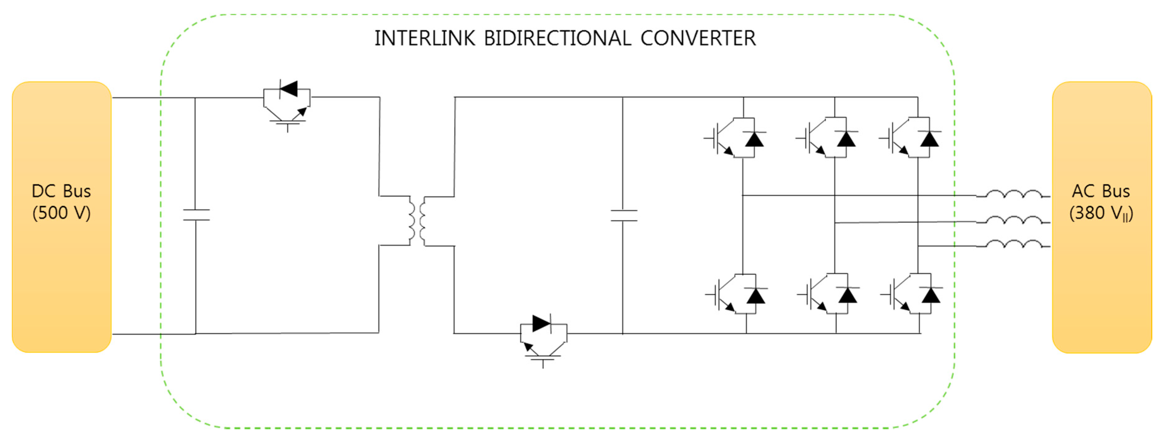
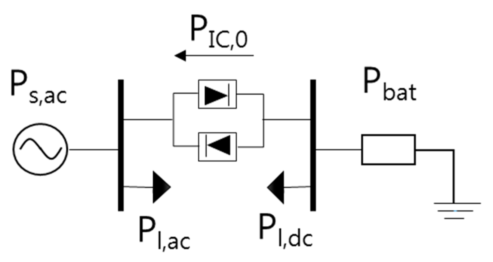
As shown in
Figure 2, IC is comprised of a DC/DC bidirectional converter connected to a three-phase inverter/rectifier. Since the converter is connected to a three-phase inverter/rectifier, a galvanic isolation is needed as protection from a short circuit. The converter is designed to be able to be connected with 750 V for the inverter side and 500 V for the DC load side.
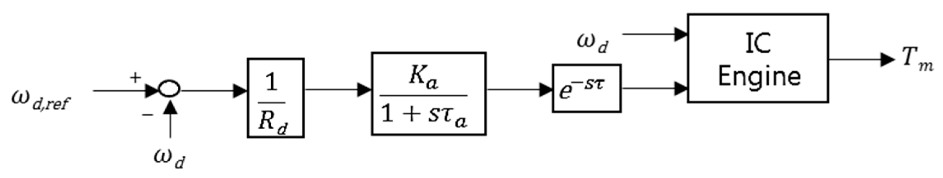
2.2. Diesel Generator Set Governor Control
A diesel generator set consists of a synchronous generator, an excitation system and a diesel engine with a governor. The diesel engine and the synchronous generator rotate at the same speed,
i.e., 1800 rpm, and no gearbox is used.
Figure 3 illustrates the governor control scheme of the diesel generator. While the microgrid is running in stand-alone mode, the diesel generator will maintain the frequency and voltage of the system. Thus, it requires a proper control system.
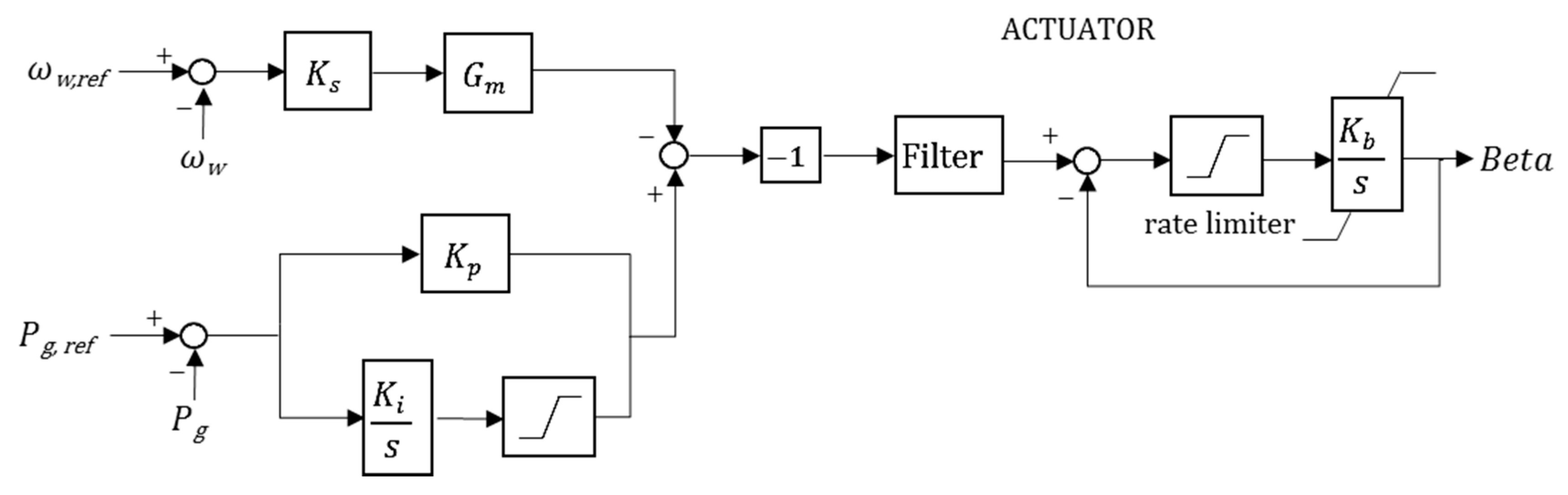
2.3. Wind Turbine Governor Control
The wind turbine model in PSCAD comprises a wind source, a turbine aerodynamic model and an electrical machine. A doubly-fed induction generator (DFIG) is used as the electrical machine. According to the convention of the induction machine, the input mechanical torque is negative. The turbine type is Wind Turbine Governor MOD 2; it is a horizontal-axis turbine with three blades. The output power from a wind turbine is given by (1).
The power control mechanism is using a pitch controller. The initial pitch angle and wind speed are inputs to this module.
Figure 4 is the wind turbine governor transfer function.
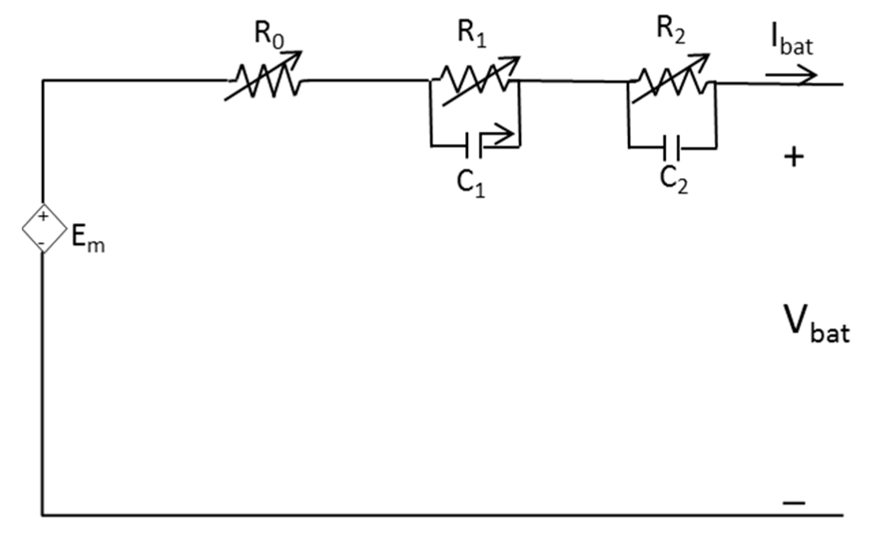
2.4. Modeling of the Battery Energy Storage System
The electrical equivalent model of the lithium-ion battery is constructed from a state of charge (SOC)-dependent voltage source followed with one resistor and two resistor-capacitor elements, as shown in
Figure 5. The open circuit voltage and resistances are defined with SOC as follows [
13]:
Battery SOC is limited from 15% as the minimum level to 80% as the maximum level. The terminal voltage of the battery is derived from Equation (7) and its multiplication with battery current results’ output power battery as in Equation (8):
3. System Operation of Interest
In the hybrid AC/DC microgrid, the IC has an important role, particularly when the microgrid is disconnected from the utility grid. Proper control and a power management system are required for the IC to manage the flow of energy from one subgrid to the other. The power management of IC control is expected to manage a bidirectional power flow between both subgrids. The hybrid AC/DC microgrid could be operated in grid-connected mode and stand-alone mode. Under grid-connected mode, the hybrid microgrid is connected with the utility grid, which acts as the slack bus. The diesel generator provides active and reactive power; meanwhile, the wind turbine generator outputs active power and consumes reactive power in the system. Furthermore, the utility grid supports a portion of power to regulate AC system frequency and voltage magnitude, while the voltage of the DC subgrid is regulated by the IC and BESS. In the case of systems having DC sources connected to the DC bus, an amount of power will be supplied. Normally, the IC manages the power balance between both subgrids.
In stand-alone mode, if the output power of sources in one subgrid cannot satisfy its load demand, the security of the system might be deteriorated. Thus, the IC requires a proper control strategy to manage load sharing among the sources for power balance. The buses experiencing a lack of power supply would take power from other buses with surplus power. In this situation, the IC would act as a power supplier for the weak subgrid and as a load for the other. In microgrids with dispersed sources, the local control method is desirable, particularly under stand-alone operation. Thus, most of the microgrids implement a droop control strategy, which does not require any communication among the sources, and the information of local frequency and voltage is used for power sharing. Basically, the frequency of the AC system and the voltage of the DC network are affected by the balancing mechanism of active power, and the voltage in the AC network is linked to that of reactive power.
4. Droop Control Strategies in an Individual Microgrid
4.1. Droop Control of AC Microgrid
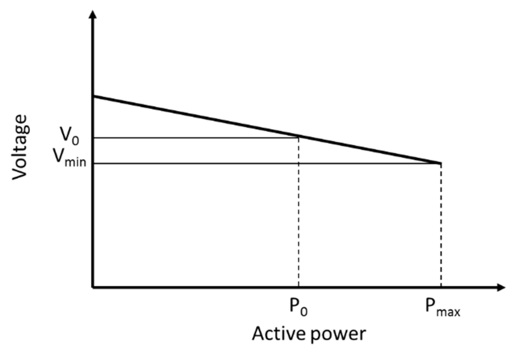
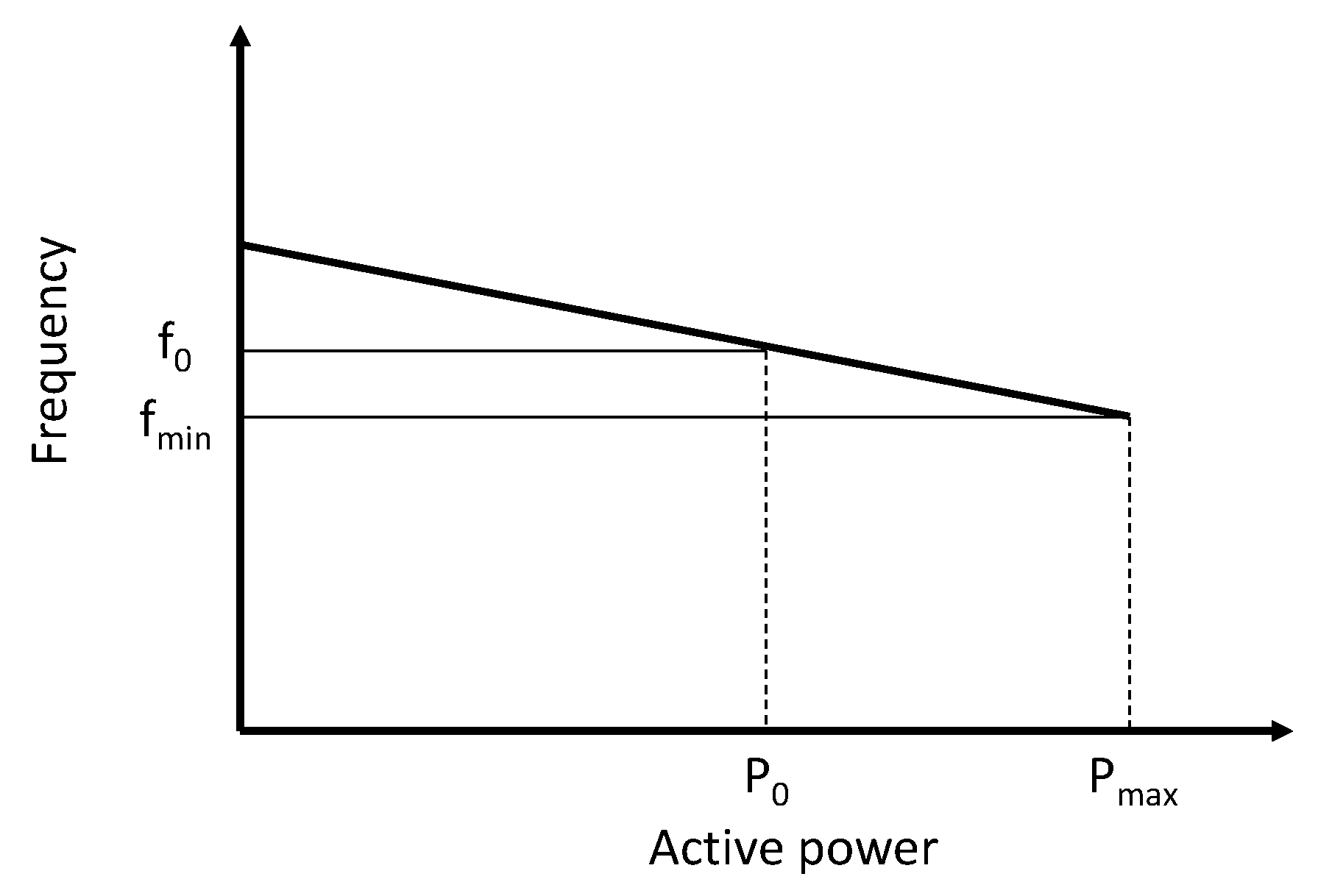
Frequency variation is caused by the power balance of an AC microgrid. The droop control scheme is usually implemented on the sources to regulate the system frequency in order to obtain proper power sharing. When frequency deviations occur in the system, the droop control will restore it by the change in active power output of the controlled sources, defined by (9). The locally-measured system frequency is compared to the reference value, and the error is multiplied by a gain constant to obtain the droop control.
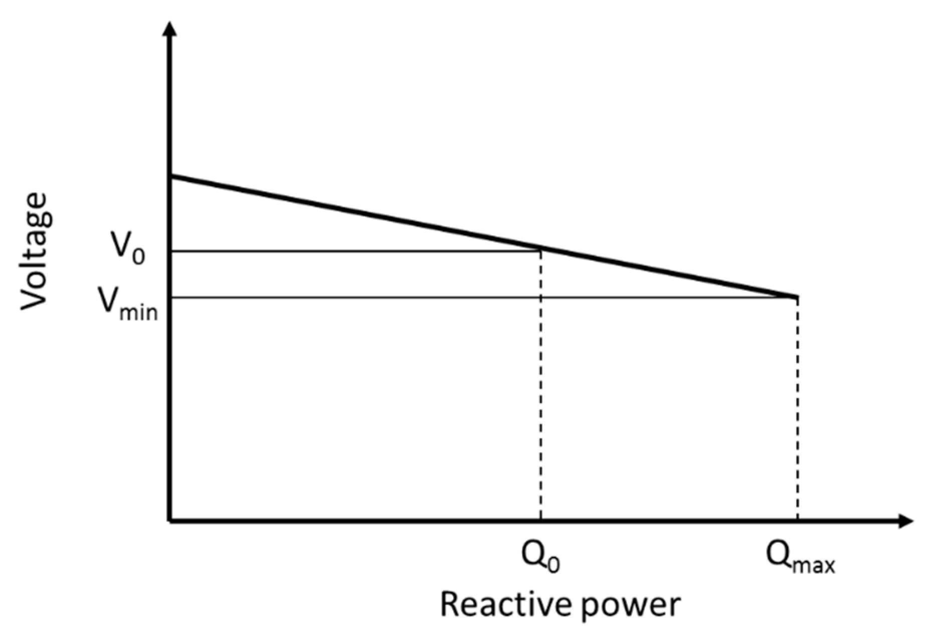
A similar strategy also could be applied to regulate AC system voltage by the change in reactive power output. For the regulation, the voltage-reactive power (V-Q) droop characteristic of (10) is used. Three-phase terminal voltages are measured, and the magnitude will be compared to its reference value. The voltage deviation is multiplied by a gain constant to obtain the droop control. In
Figure 6 and
Figure 7, the frequency-active power (f-P) and V-Q droop characteristic curves are shown.
4.2. Droop Control of the DC Microgrid
In the DC microgrid, the active power sharing is managed by the output voltage magnitude of converters. There is no control scheme for reactive power sharing and frequency. The droop control scheme for voltage regulation is defined by (11) with
Figure 8.
5. Proposed Droop Control Strategy
Hybrid microgrids need different droop control schemes compared to individual AC or DC microgrids. The IC needs to manage the bidirectional power flow between AC and DC subgrids. Both subgrids have distinct droop characteristics, and the IC should have a proper coordination control strategy for power sharing. While one subgrid experiences excessive power generation, the IC should be able to get the power injection to the proper level to mitigate the problem. At that time, the IC acts as a supplier for one subgrid and as a load for the other.
In this proposed droop control strategy, active power sharing will be performed by enforcing the frequency deviation on the AC subgrid to be equal to the bus voltage deviation on the DC microgrid. The difference of both values in per unit (p.u.) will be the input of the proportional controller with gain
to generate a new active power reference transferred by the IC. When using a stiff droop constant, the IC tried to reduce the deviation of the frequency of the AC subgrid and the voltage of DC subgrid from their nominal values before other DERs with primary controllers. However, it is not recommended to use a much lower value of
Rp for the IC from those of the DERs, because the main sources of the additional active power are the DERs.
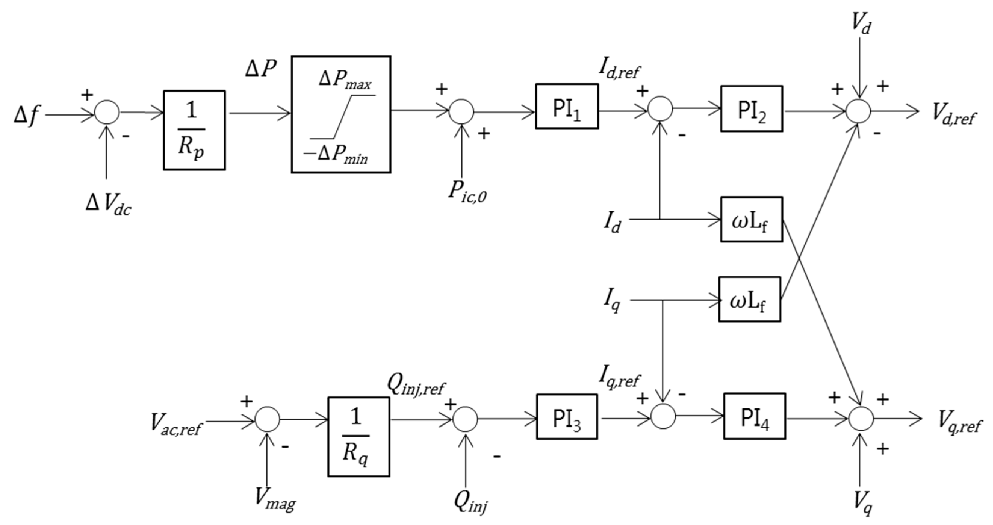
As shown in
Figure 9 for the proposed droop control scheme of the IC, positive error means power is flowing from the DC subgrid to the AC subgrid, meanwhile negative error means power flow from the AC subgrid to the DC subgrid.
Figure 10 illustrates the power setting point of the IC and its positive direction. Under grid-connected mode, the installed BESS in the DC subgrid might not discharge any power, but charge power if SOC is not within the acceptable range. When the SOC level reaches its maximum limit, the battery will be in idle mode; this means that it does not charge nor discharge power. The DC load demand is supplied by sources in the AC subgrid, by the transfer of power through the IC. This condition causes the transferred power of the IC to be added by the initial active power, as defined in (15).
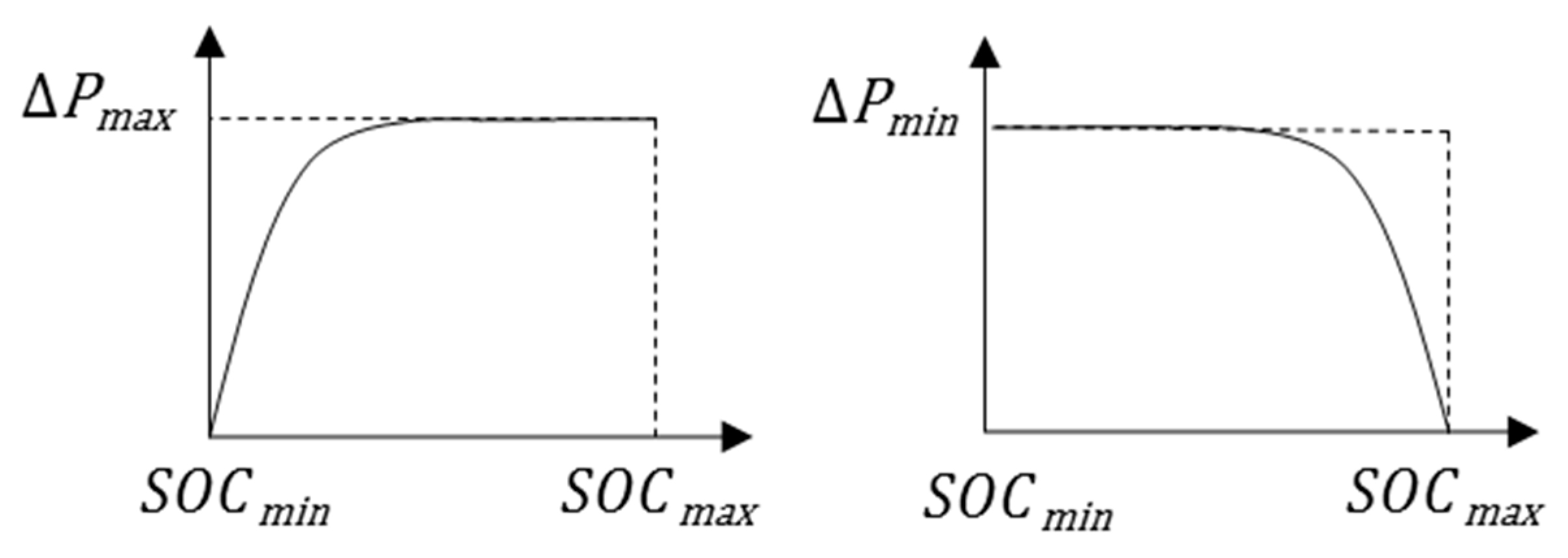
In the proposed control scheme, as in
Figure 9, the change in the active power transfer through the IC,
, needs to be limited based on the SOC of the battery, because the battery in the DC subgrid can respond more quickly than other resources, and it can behave like a source and a load. In
Figure 11, the limiting parameters of
and
depend on the level of SOC, and discharging power is denoted by a positive sign and charging power by a negative one. Power flow from the DC to the AC subgrid is assumed as positive power transfer, as in
Figure 10. Under those conditions where positive
is required, the upper level of
is limited by
when the battery SOC is higher than its minimum level. However,
is reduced to zero when the battery SOC is quite close to
, as in
Figure 11. Otherwise, the change in power injection with a negative sign is needed, and the lower level of
is limited by −
;
is reduced to zero when the battery SOC reaches its maximum level.
In order to obtain current tracking reference , injection will be controlled through a proportional-integral (PI) controller. The error of from its reference value then will be regulated by another PI controller to achieve .
Control of reactive power sharing for a hybrid microgrid is similar to the AC microgrid scheme. Current reference,
, is produced by the PI controller with
as the input. There is no initial reactive power value, since there is no reactive power transfer under grid-connected mode.
will become zero if power flows from the AC to the DC subgrid since the DC subgrid does not require reactive power. Current reference
is generated by the PI controller with
as the input.
is obtained through another PI controller, which manages the error of
. The direct-quadrature (d-q) outputs from the PI controllers are transformed back to three phase (a-b-c) form to generate the signal for the pulse width modulation (PWM) converter.
6. Coordination Control of IC and the BESS Converter
Under normal operation, power balance in the whole system is guaranteed because of the support from the utility grid. Meanwhile, if one microgrid experiences a lack of power supply under stand-alone operation, the IC needs to manage the power sharing between both subgrids in order to maintain system security. Besides, the BESS converter should work properly by charging or discharging actions, regarding the system requirement.
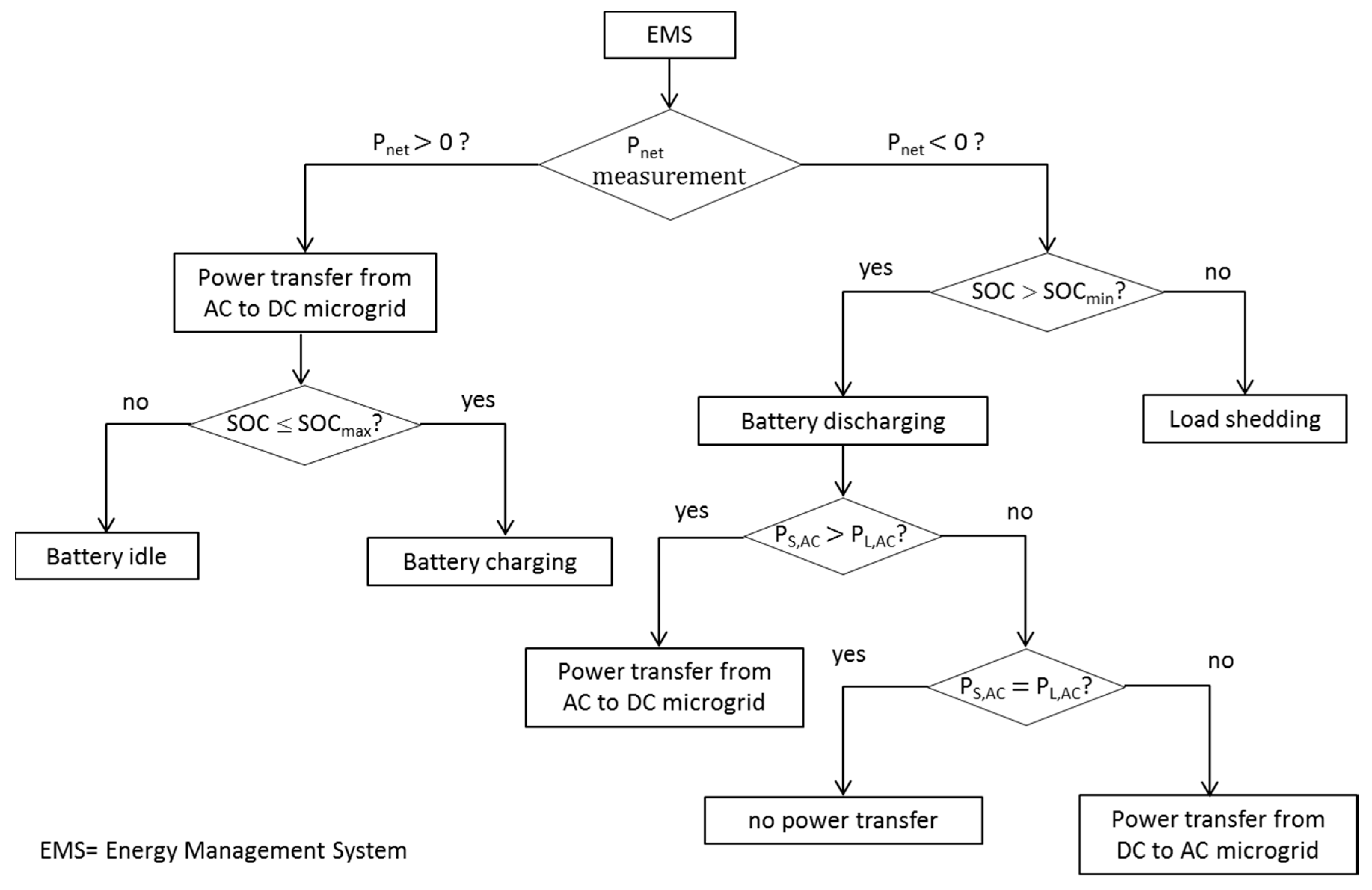
The power management scheme for the proposed hybrid microgrid model under stand-alone operation is shown in
Figure 12. The scheme determines the power transfer direction controlled by IC and battery operation mode controlled by the battery converter. The battery as a grid-forming unit has to handle the power variations that take place in the entire hybrid microgrid [
14].
is the active power difference among the sources and demand load in the microgrid model, as in (17), and it then represents the active power amount that needs to be supplied or consumed by the battery.
Under stand-alone operation, the power management scheme is crucial for secure system operation. As in
Figure 12, the battery SOC and the imbalance between generation and load in the whole microgrid determine the operation mode of the battery and the direction of power injection through the IC. If the sources’ output power is more than the load demand, the IC will enforce the increase in transfer power to the DC subgrid since the sources are only installed in the AC subgrid in the system configuration. When the battery SOC level has room to charge, the battery will be in charging mode. However, if the SOC level is quite close to the SOC maximum limit, the battery will be in idle mode, and some other countermeasures need to be taken.
In the case where the sources could not satisfy the load demand in the whole microgrid system and the SOC level has room to discharge, the battery will be in discharging mode. If the sources cannot support the load demand in the whole system, the power management scheme needs to consider two cases; if the net power in the AC subgrid is negative, the IC would transfer the surplus power to the AC subgrid. If the AC subgrid is in the power balance condition, the IC would not change the transfer power. In both cases, the battery needs to discharge the proper amount of power, and it can be automatically done by the voltage regulation control of the battery converter. However, discharging cannot be sustained because of the limited capacity. As the last resort, a load shedding scheme is carried out if the SOC level is quite close to its minimum limit, and then, the microgrid is restored from its deficiency in power supply.
In some particular cases, the system frequency is not able to be restored, even though the planned load shedding is applied. This is caused by the power injection to the DC subgrid and the droop control action for the DC voltage regulation; in other words, the IC needs to share some amount of power with the DC subgrid. Thus, the DC voltage deviation and initial setting point of active power transfer need to be limited according to the AC subgrid frequency deviation, following the equations below.
By applying the limitations above, Equations (14) and (15) change into (20) and (21). Furthermore, in the scheme, a certain frequency deadband is employed to exempt the small frequency deviation.
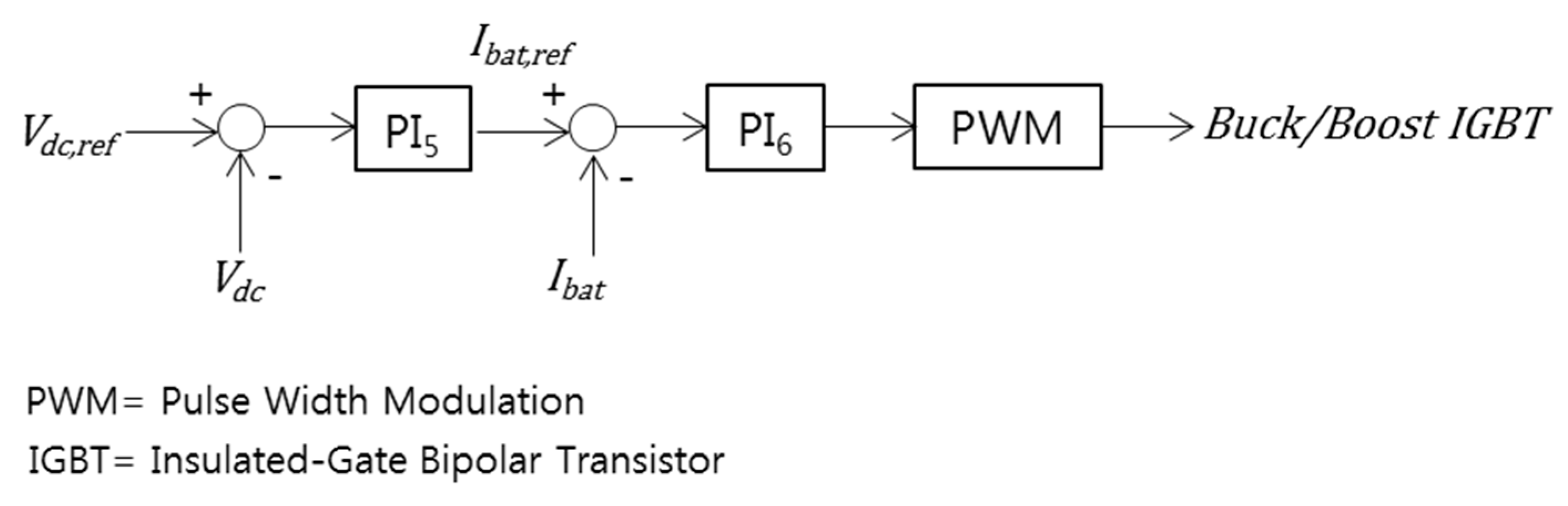
In the DC subgrid, the power imbalance causes the voltage bus to deviate from its nominal value. The connection between BESS and the DC bus is interfaced by the bidirectional DC/DC converter that will take action once the DC voltage deviates. When the DC link voltage drops due to the lack of power supply, the BESS controller will provide the change in current reference, flowing to the DC bus. In this condition, the converter acts as a boost converter, and the battery discharges power.
Otherwise, in the case where there is excess power output from AC sources and the IC gets the amount of power to the DC subgrid, the DC bus voltage might be increased. In this case, the controller of the BESS will provide the new current reference point, so that the battery absorbs the power from the DC bus. Then the DC/DC converter behaves as a buck converter, and the battery is in charging mode. The control scheme for the BESS converter is shown in
Figure 13, and it was originally from [
15].
7. Simulation Results
In normal operation, the AC and DC microgrids are usually in the secure operation condition due to the power balance that can be made because of the external system support. In the simulation, nominal values of frequency, AC voltage and DC voltage were defined as 60 Hz, 380 V (line to line) and 500 V, respectively. Since there were no power sources in the DC subgrid, the DC load demand was mainly supplied by the AC sources, and the IC initially transferred power from the AC subgrid to the DC subgrid during grid-connected mode. The rated active and reactive power for the IC were 20 kW and 10 kVAR, respectively, and the IC initial setting point was determined around 20 kW transferring power from the AC to the DC microgrid. In the simulation, and were all set to 0.05 for the IC droop controller.
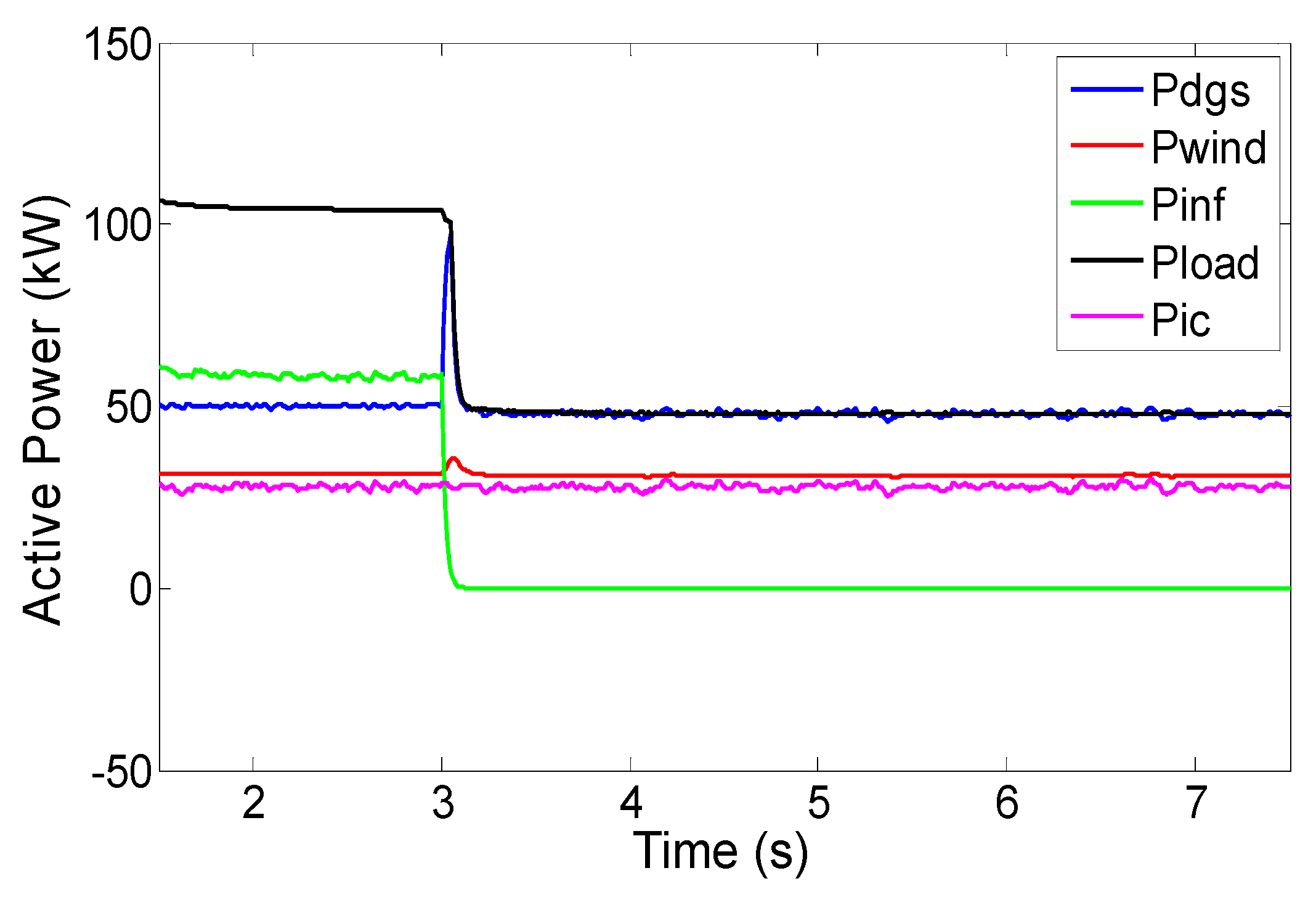
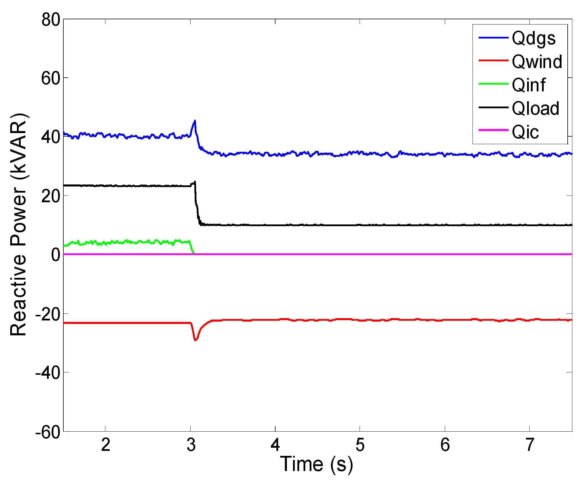
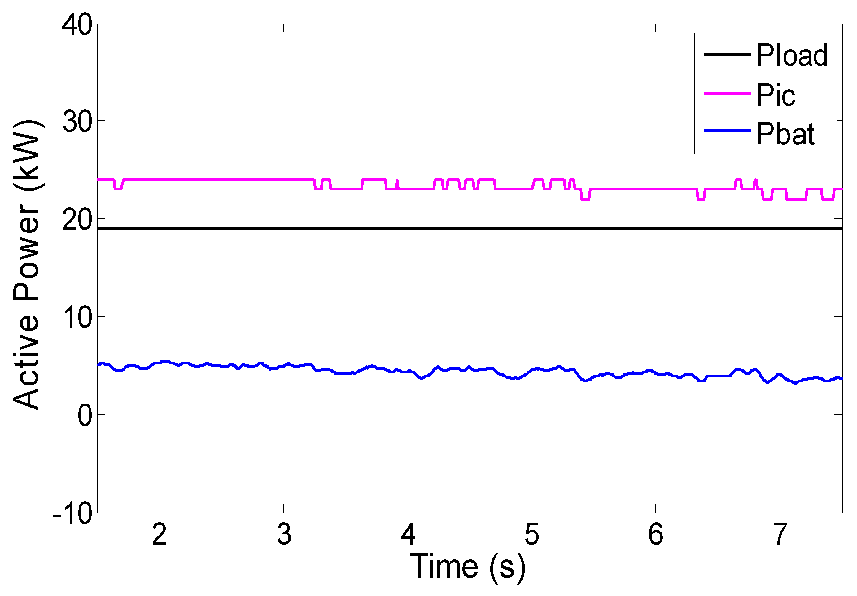
In the first case, it was assumed that the battery SOC approached its minimum level, 15.0%. The AC sources and utility grid supplied power around 134 kW and 23 kVAR, and the AC load demand was around 105 kW and 23 kVAR. DC load demand was 19 kW. Since the battery had very low SOC and the load demand was rather high, the DC bus voltage slightly decreased to 487.5 V, and hence, the droop control for the IC provides the corresponding power setting point. Thus, the active power of 27 kW was transferred from the AC subgrid to the DC subgrid. According to (17), the difference of the IC power and DC load was equal to the amount of charging or discharging power of BESS. Due to conversion and line losses, just around 5 kW was able to be charged by the battery.
Figure 14,
Figure 15 and
Figure 16 show the power generation and consumption curves of the whole elements in the AC and DC subgrids.
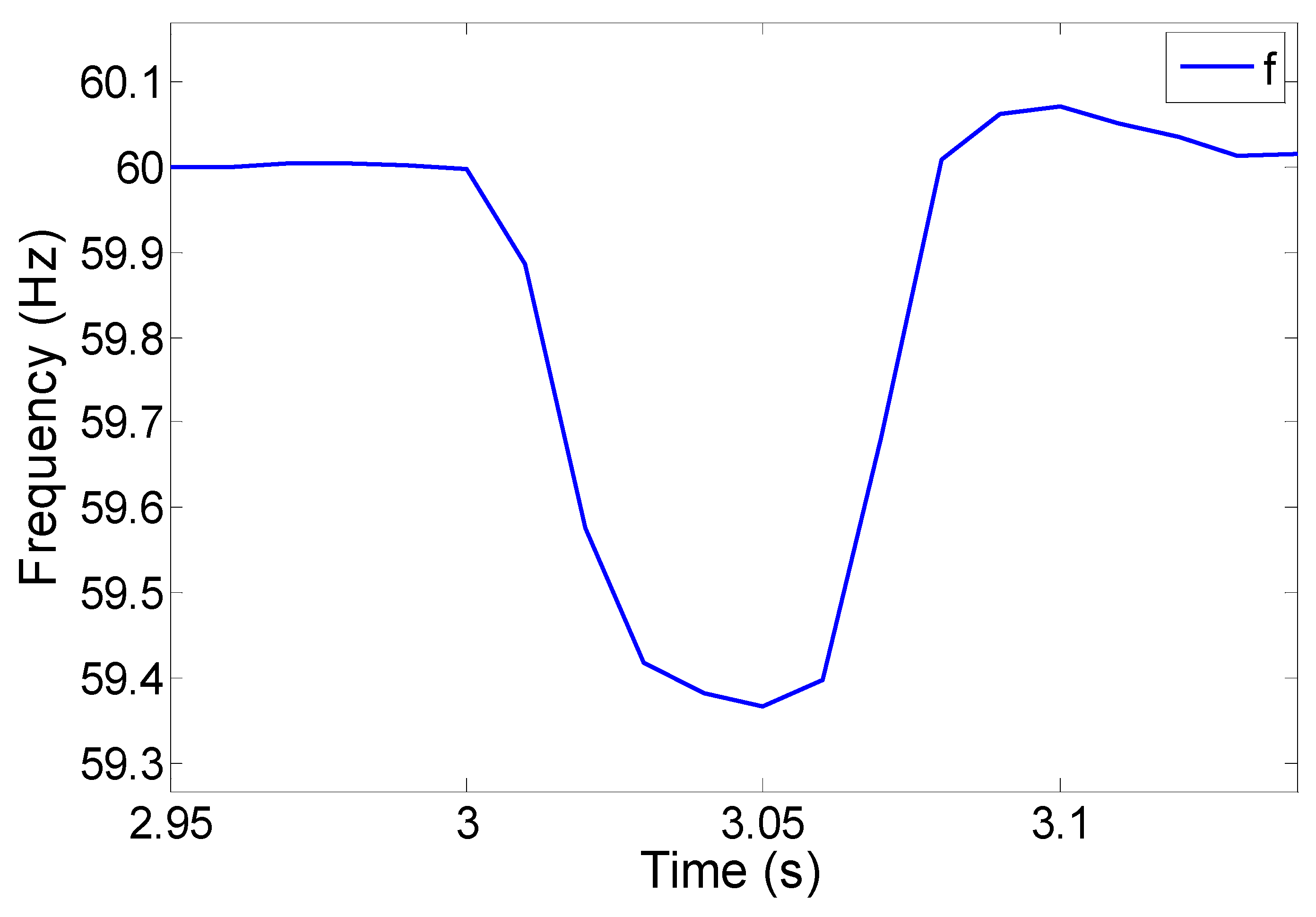
At
t = 3 s, the static switch that connected the AC microgrid to the utility grid was opened. The operation mode of the hybrid microgrid gets into stand-alone mode. Power support around 59 kW and 4 kVAR from the utility grid was not supported anymore, and then, the frequency decreased to 59.4 Hz in the AC subgrid. When the operation mode was changed, the frequency kept decreasing, since there was not enough power supplying the load demand, so load shedding needed to be applied by the power management scheme, as in
Figure 12, and then, the frequency got restored. The change of frequency is shown in
Figure 17. In this situation, the IC tried to increase the power transfer to regulate the frequency, but that action was confined because the SOC level of the battery is close to its minimum, and hence,
is quite close to zero.
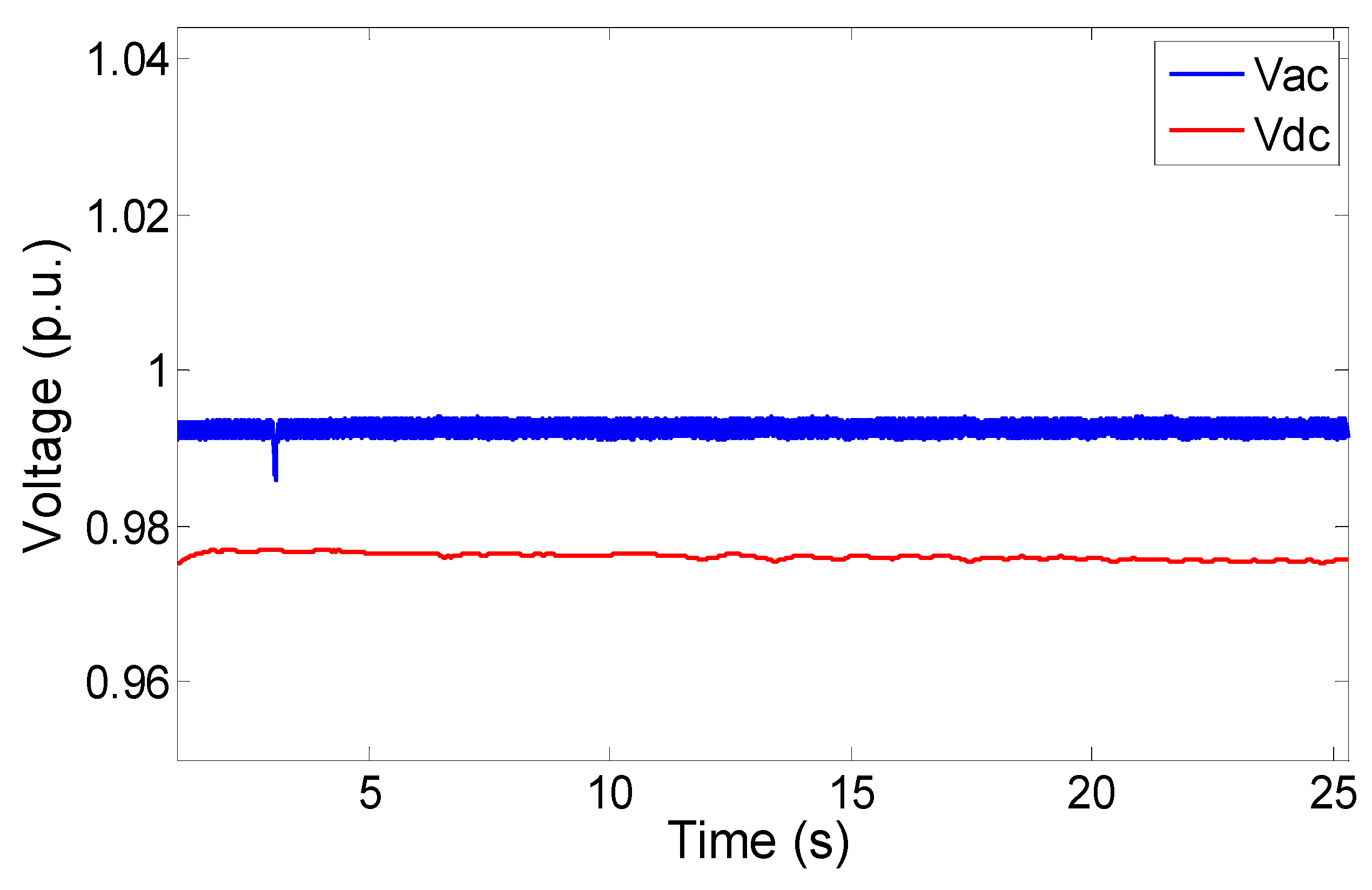
While the operation mode was changing, the DC bus kept receiving the power from the AC sources, so the bus voltage was maintained within the acceptable range, as in
Figure 18; meanwhile, the AC subgrid voltage slightly decreased due to the
V-
Q droop control.
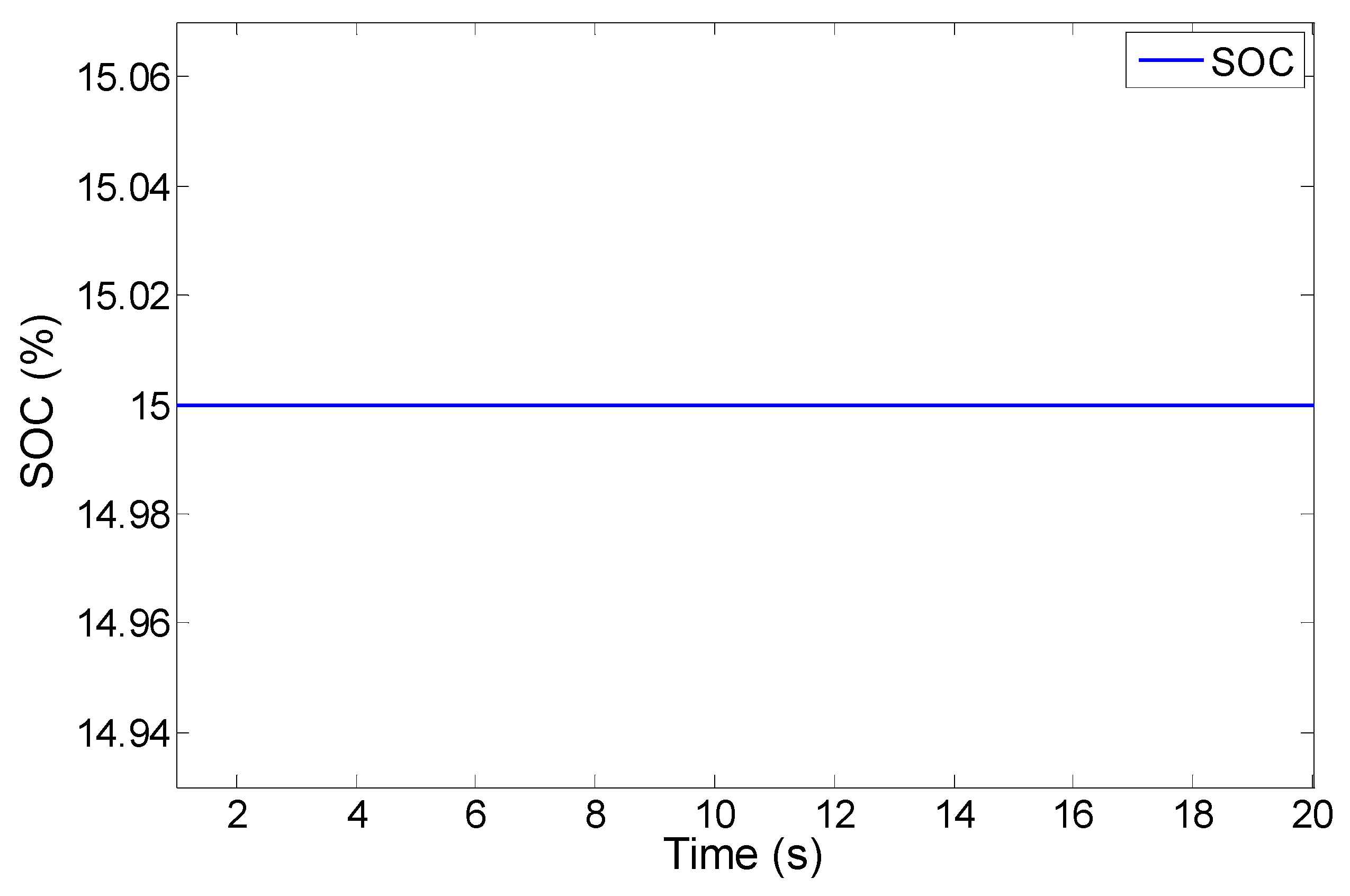
Figure 19 shows the SOC curve during the simulation.
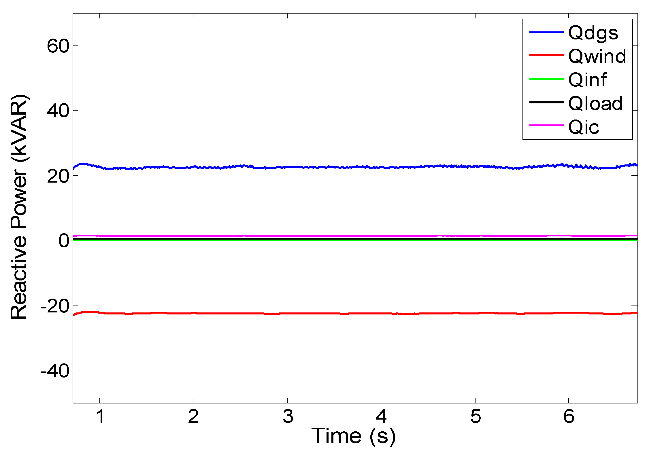
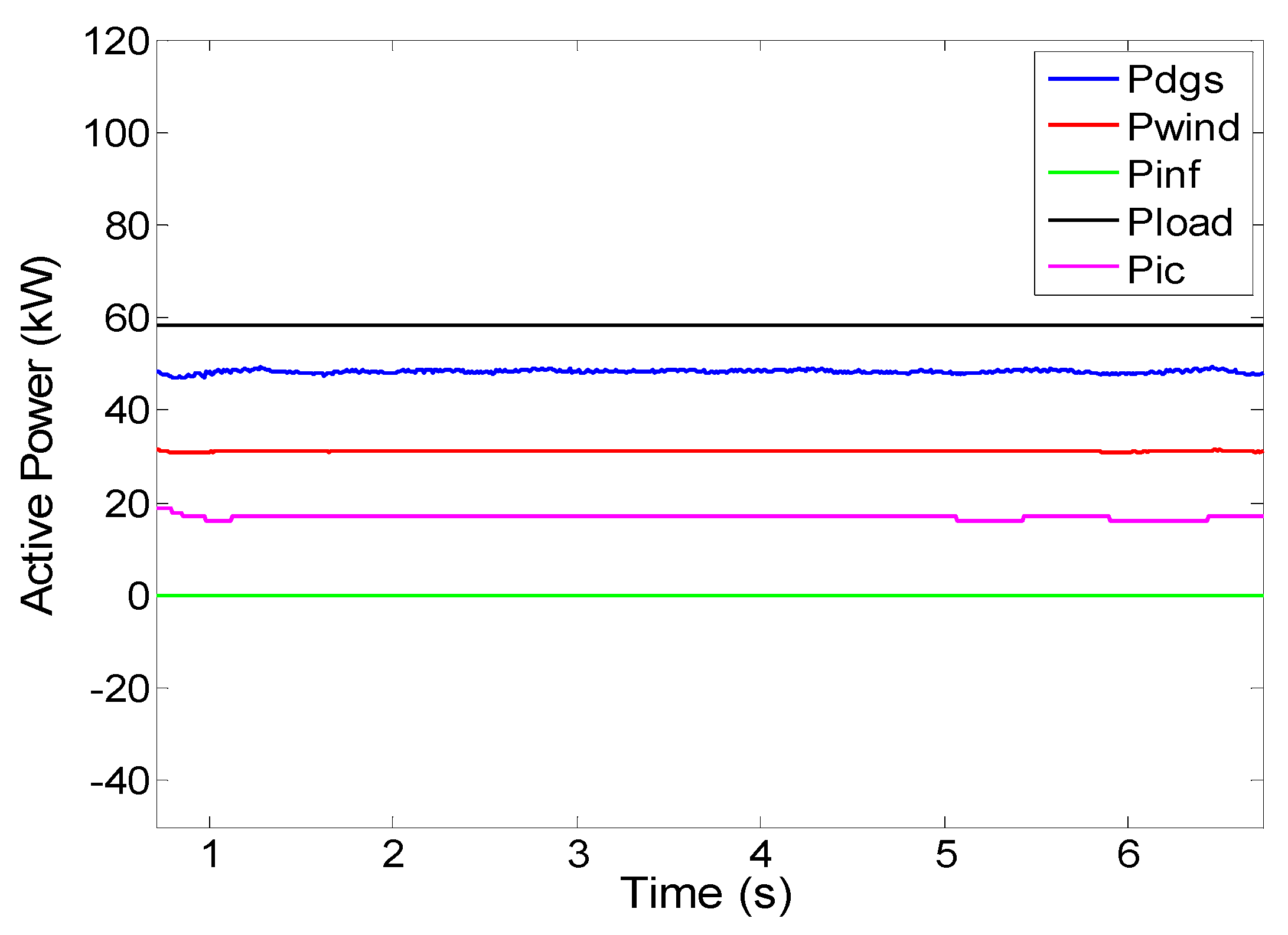
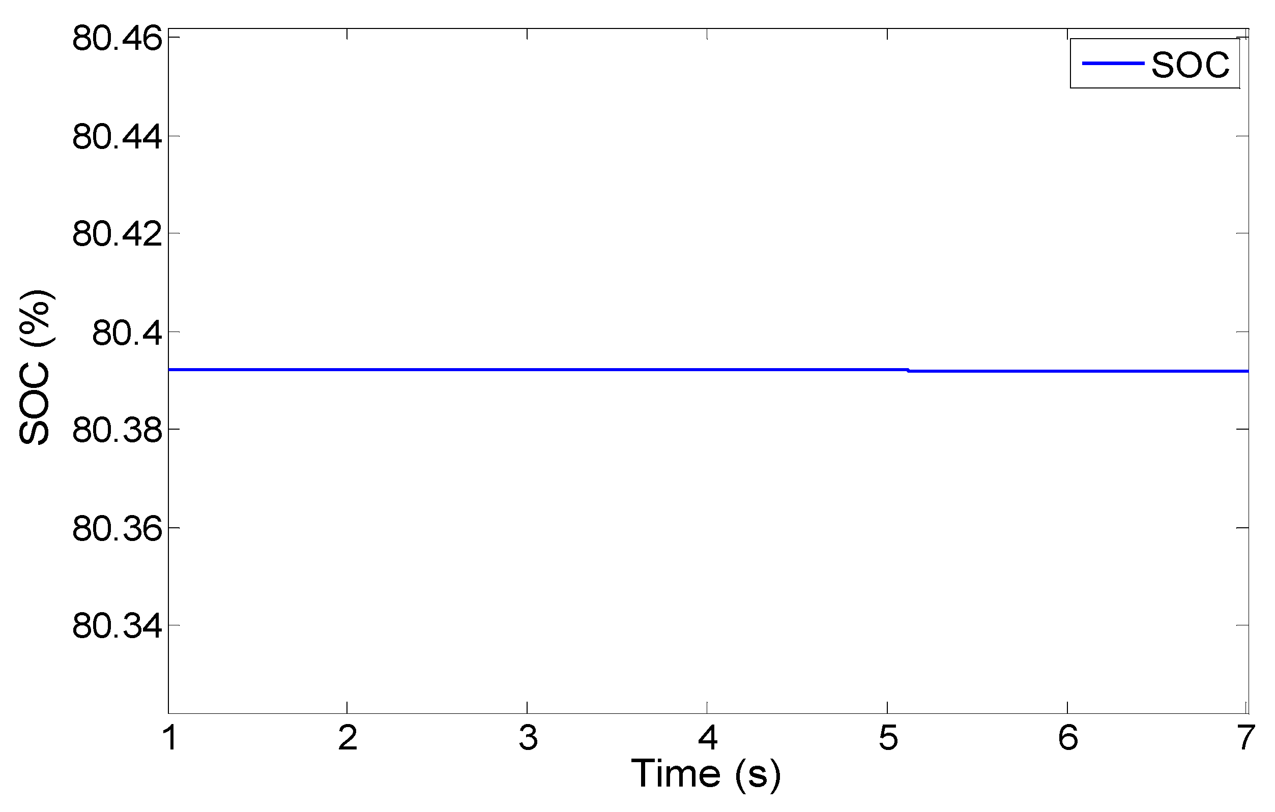
In the second case, the hybrid microgrid was initially operated under stand-alone mode. The battery SOC was at its maximum level, around 80%. The consumption of DC load was 17 kW; meanwhile, the AC loads were 58 kW and 0.5 kVAR. The AC sources generated power around 78 kW and 1 kVAR, so there was excess power around 3 kW in the AC subgrid. Since the battery SOC already reached its maximum value, the change in power through the IC,
, that flowed into the DC microgrid was limited by
, and
was set close to zero because the battery was fully charged. Thus, BESS could not charge the net power.
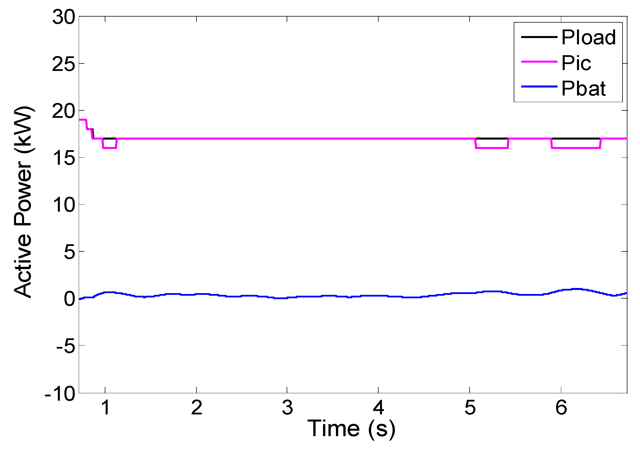
Figure 20,
Figure 21 and
Figure 22 show the power generation and consumption curves of the whole elements in the AC and DC subgrids in the simulation.
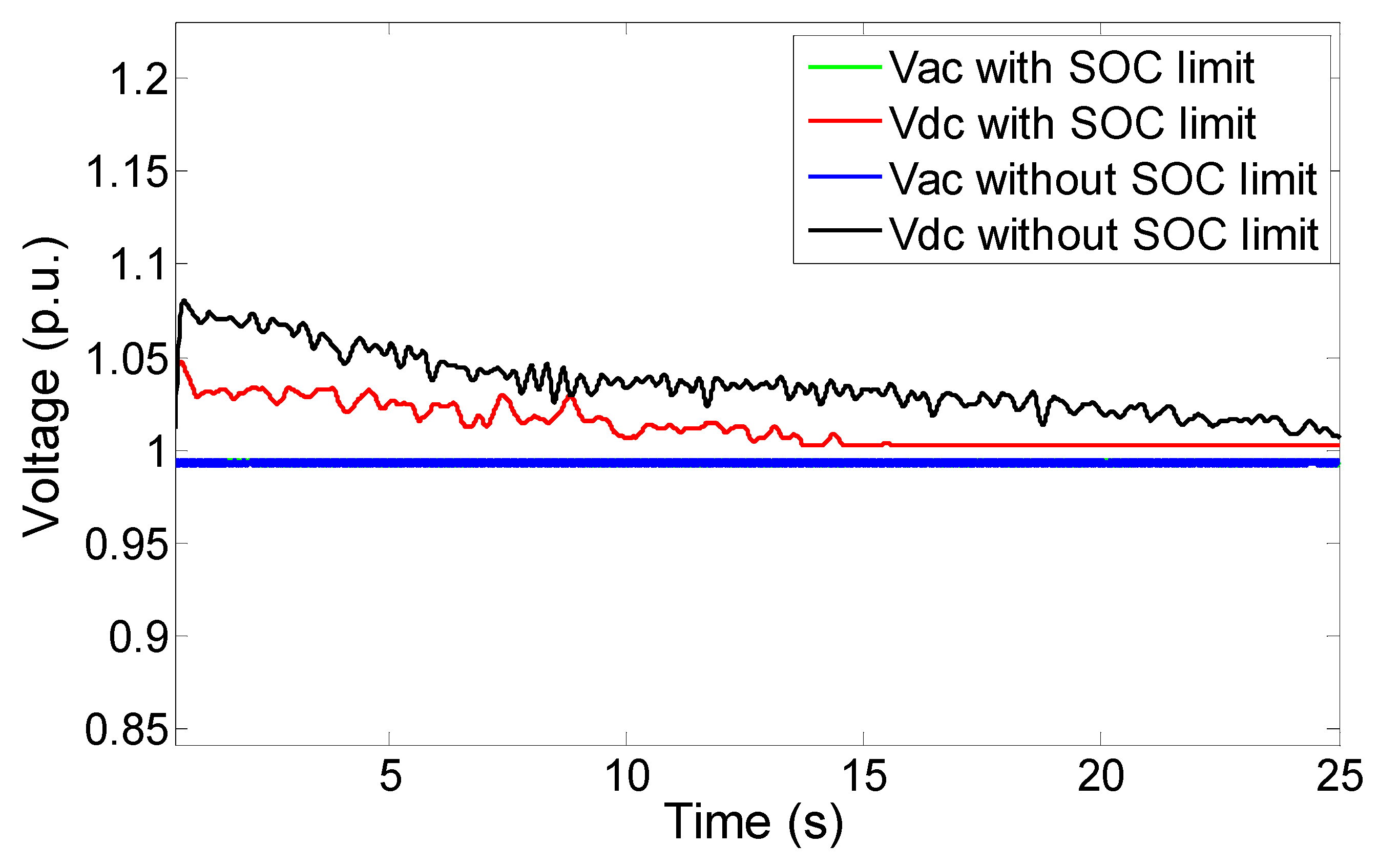
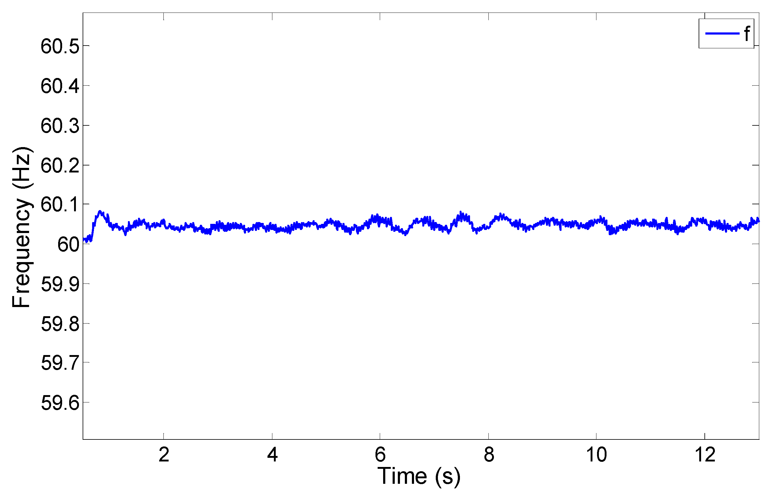
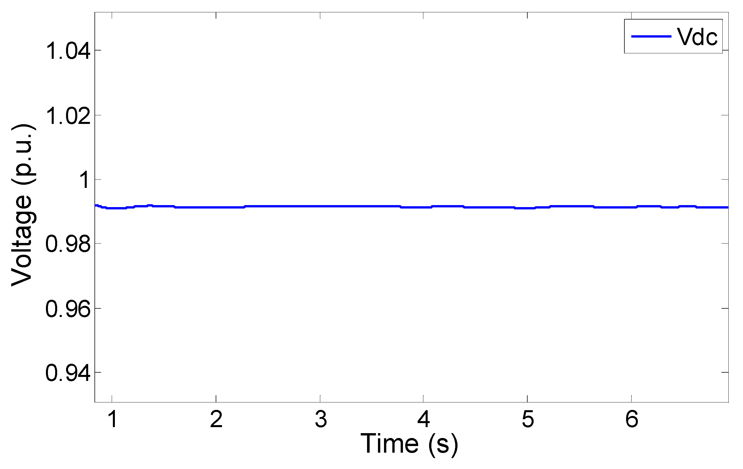
In this case, from the initial setting point of 20 kW from the AC to the DC subgrid, the IC power finally became 17 kW to satisfy the DC load. In this situation, the slight increase in the AC system frequency from its nominal value occurred, as shown in
Figure 23. Pertaining to the DC voltage, it was a bit higher than 1 p.u., since the DC subgrid had excess power support. The deviation of DC bus voltage was gradually reduced by the coordination control of the IC and the battery, as shown in
Figure 24. Without considering the SOC limit, the power to the DC subgrid was not managed properly, compared to the proposed droop control strategy. It initially caused a higher DC subgrid voltage from the nominal value and took a longer time to regulate it.
Figure 25 shows the SOC curve during the simulation. To further restore the AC system frequency back to its nominal level, some action needs to be taken, such as increasing loads or reducing power generation by the automatic governor control (AGC) action of the AC sources.
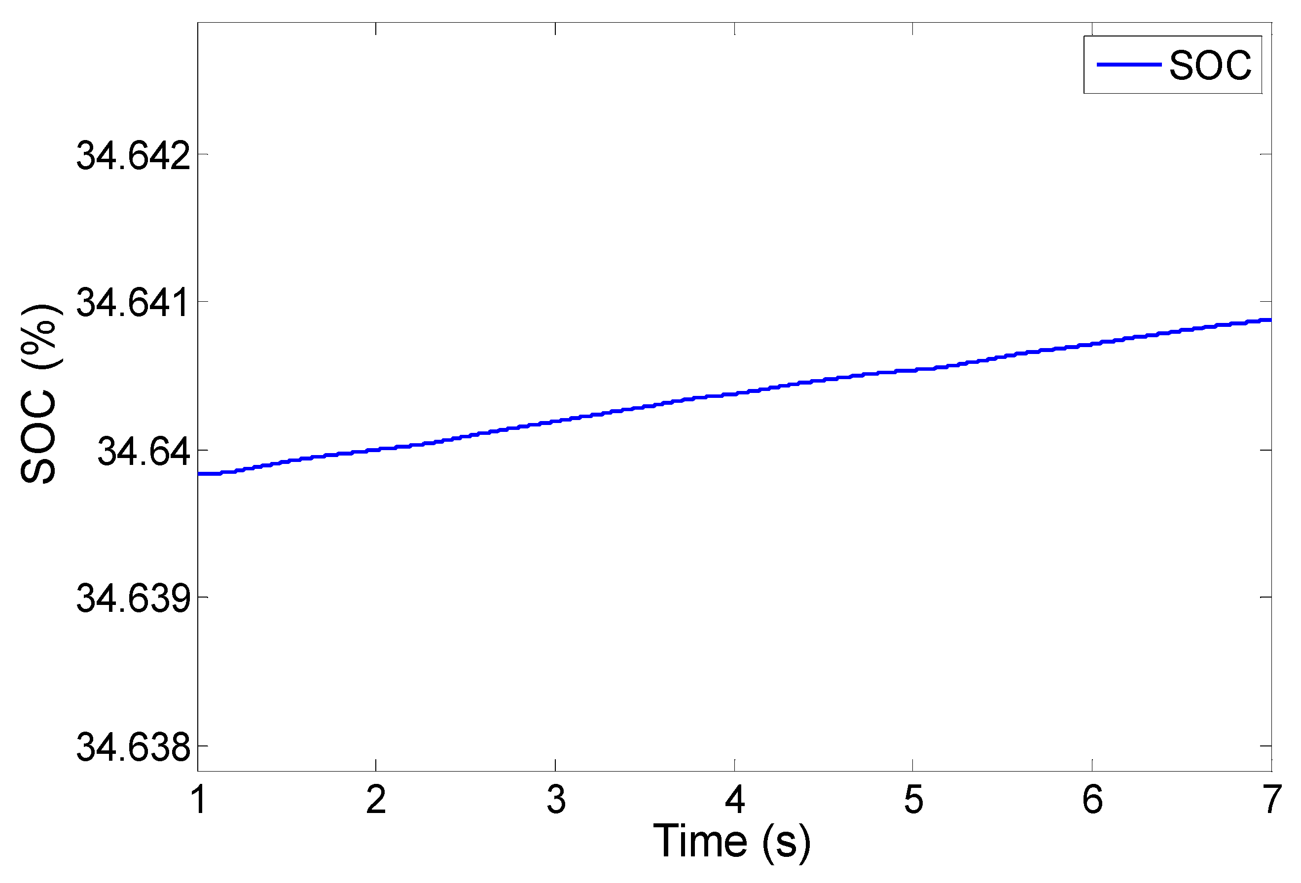
If the battery SOC level in the second case has room to do the charging action, the battery can absorb power, as mentioned in the power management scheme. Furthermore, another simulation was performed by setting the battery SOC to 34.64%. The excess power in the microgrid could then transfer into the battery by the converter control to regulate the DC voltage. From
Figure 26 and
Figure 27, one can notice that the DC voltage was properly regulated and that the SOC level was increased by its charging action.
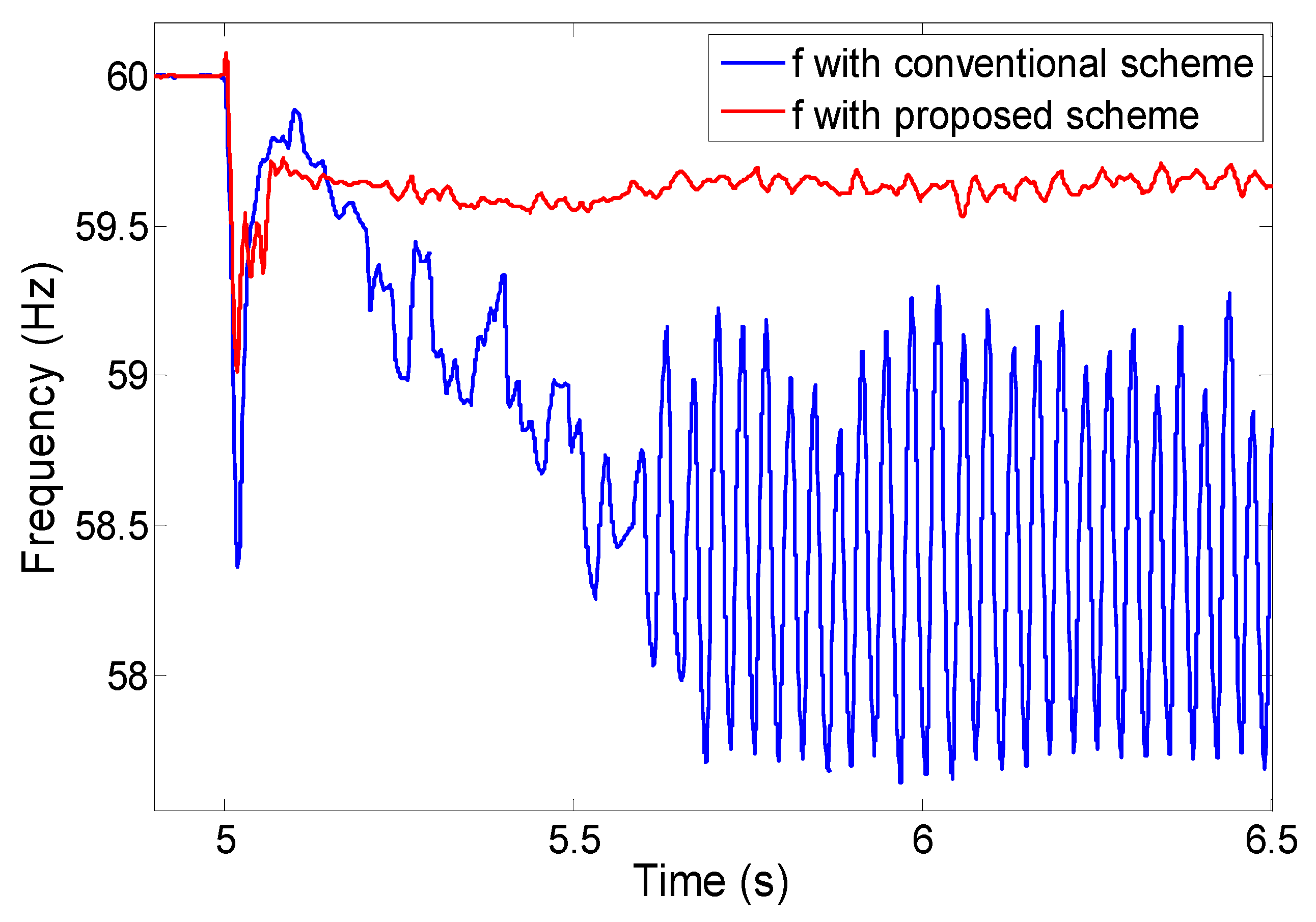
Another case was studied with slightly modified system parameters from the first case, and the utility grid support was increased by around 10 kW. At
t = 5 s, the system operation mode changed into the stand-alone hybrid microgrid. To restore the system frequency, a portion of the AC load was shed, and the amount was 75% of the power support from the utility grid before the mode change. Using the conventional droop control scheme, at the beginning, the frequency was able to increase, approaching the nominal value by the load shedding action, but around 0.2 s after the action, the frequency started decreasing and severely oscillated around 58.5 Hz. To avoid the frequency instability, the proposed control strategy applied the action for limiting the IC injection.
0.5-Hz frequency deadband was used on the limitation scheme of DC voltage and the IC initial active power setting point; that is, the incremental power for DC voltage regulation and the IC initial set point was confined to (18) and (19). From
Figure 28, one can notice that the system frequency was restored and settled down around 59.65 Hz when using the proposed scheme.
8. Conclusions
The objective of the IC controller is to regulate the frequency of the AC subgrid and the bus voltage of the DC subgrid by the control of the active power injection via the IC. The change in the power injection is followed by the support of the BESS in the DC subgrid because of its DC bus voltage regulation. Thus, when the SOC of the BESS is exhausted or fully charged, the change in the active power injection needs to be managed along with the physical limits of the battery SOC. The proposed coordination control strategy can provide a smooth transition on power transfer through the IC of the microgrid in stand-alone mode, and from the simulation results, one can notice that the control strategy can manage the power transfer effectively, even when a load shedding is applied in weak conditions.


