Article

Effects of Different Factors on Electrical Equipment UV Corona Discharge Detection

1
State Key Laboratory of Power Transmission Equipment & System Security and New Technology, School of Electrical Engineering, Chongqing University, Chongqing 400044, China
2
School of Electric Power, South China University of Technology, Guangdong 5010640, China
*
Author to whom correspondence should be addressed.
Energies 2016, 9(5), 369; https://doi.org/10.3390/en9050369
Submission received: 9 March 2016 / Revised: 4 May 2016 / Accepted: 9 May 2016 / Published: 16 May 2016

Abstract

:
As a non-contact discharge detection method, ultraviolet (UV) imaging can rapidly, directly, and securely detect corona discharges. Therefore, UV imaging has been widely applied to power systems. To study the influences of different factors on UV corona discharge detection, two typical types of UV imagers (DayCor®Superb and CoroCAM®6D) were utilized. Results show that the observation angle has little impact on UV detection if no obstacles block the detection line of sight. Given that different UV imagers have different optimal imager gains, photon numbers under different gains could be calibrated to the values under optimal gains in accordance with the gain correction formula. Photon numbers decrease with the increase in the square of observation distance. Detection results under different observation distances could be corrected to the contrast distance after the detection of electrical equipment. The photon numbers of different UV imager types could be corrected in accordance with the instrumental correction factor. The results of this study can provide references to improve the applications and standardizations of UV imaging technology in corona discharge detection.

1. Introduction

Owing to contamination, rain, structural defects, and poor contact with conductors, electric field distributions in high-voltage equipment in operation are uneven, which results in the phenomenon of corona or arc discharge. Corona discharges can cause insulation aging, cracking, and insulation accidents, which affect the safe operation of electrical equipment [1,2,3,4]. Therefore, timely detection of the location and intensity of corona discharges is important for the secure operation of power systems.
The current methods utilized to detect corona discharges in electrical equipment mainly include visual observation, ultrasonic method, infrared imaging method, ultrahigh frequency method, and ultraviolet (UV) imaging [5,6]. UV imaging is a non-contact live detection method that can rapidly, directly, and securely detect partial discharges in equipment. The UV wavelength of corona discharge radiation ranges from 200 to 400 nm [7,8], but UV imagers can only detect UV light signals in the 240 to 280 nm range, which corresponds to the solar-blind area [9,10]. That is to say the effect of sunlight can be excluded during corona and arc discharge detection by UV imaging. Given its advantages, UV imaging has been widely applied and studied worldwide [11,12,13,14,15,16,17].
As an important quantitative parameter in detecting corona discharges by UV imaging, photon number has been widely utilized in both laboratory research and field tests. In detection, photon number can rapidly, directly, and conveniently reflect partial discharge. However, in practical applications, this parameter still has some deficiencies because of its complex relations with observation angle, imager gain, observation distance, and imager types. To overcome these problem, several scholars have attempted to quantify discharges by UV image processing [18,19,20]. However, more unified conclusions are required. Owing to the fact the observation angle, observation distance, imager gain, and imager types are different in detection and comparisons of the photon numbers of different detections is lacking, discharges cannot be accurately quantified. Therefore, the effects of factors, such as imager gain and observation distance, on photon number detection should be evaluated.
In this study, two representative UV imagers (DayCor®Superb and CoroCAM®6D) were utilized in a series of corona discharge tests. The effects of observation angle, imager gain, and observation distance on photon numbers were comprehensively analyzed. These results supplement the application of UV imaging method and complete the UV detection project. Meanwhile, different types of UV imager are contrasted for the first time in UV detection, and a correction formula between two UV imagers is proposed, which is beneficial to realize comparisons between different UV imagers. Based on the above research, different detection photon numbers could be corrected and this is beneficial to realize comparisons of corona discharges under different conditions. The application of UV imaging in corona detection is further improved.

2. Experimental Facilities, Specimens, and Test Procedures

2.1. Experimental Setup and UV Imagers

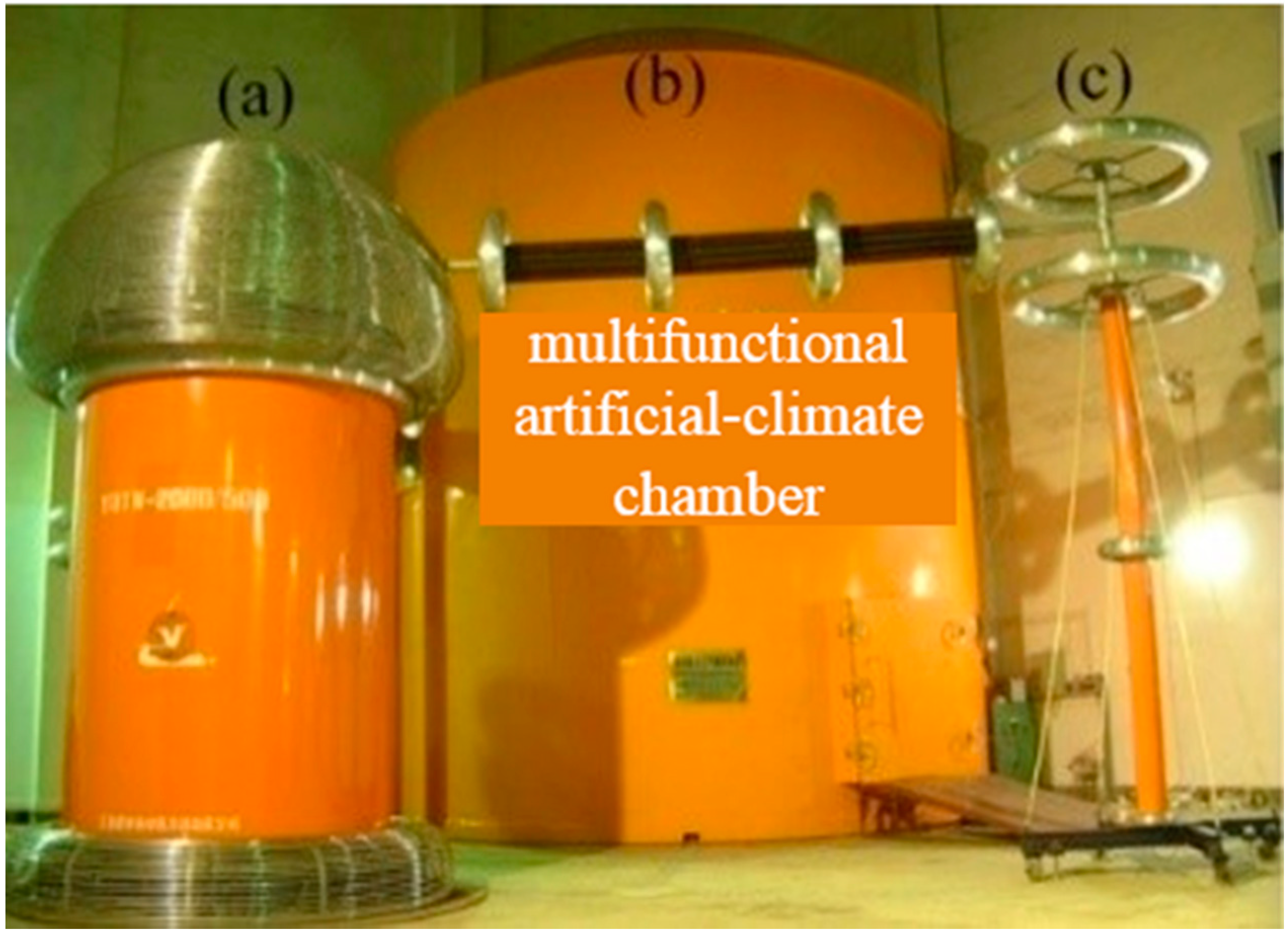
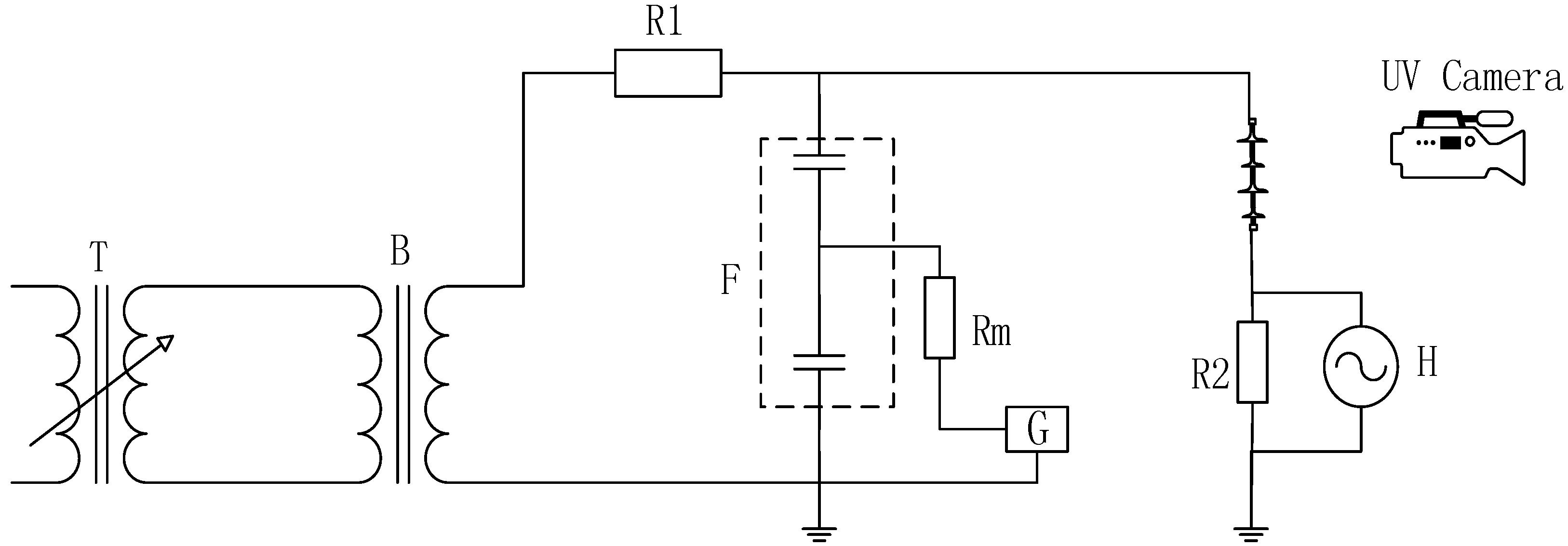
Experiments were conducted in a multifunctional artificial-climate chamber that has a diameter of 7.8 m and a height of 11.6 m (Figure 1a). Power is provided by a 500 kV/2000 kVA testing transformer (Figure 1b) with a maximum short-circuit current of 75 A. The output voltage waveform distortion factor is less than 3%, the magnitude of partial discharge is less than 10 pC, the short-circuit impedance of the system is less than 6%, and the applied voltage is measured with a 500 kV capacitive voltage divider, as shown in Figure 1c. A schematic of the test circuit is shown in Figure 2.
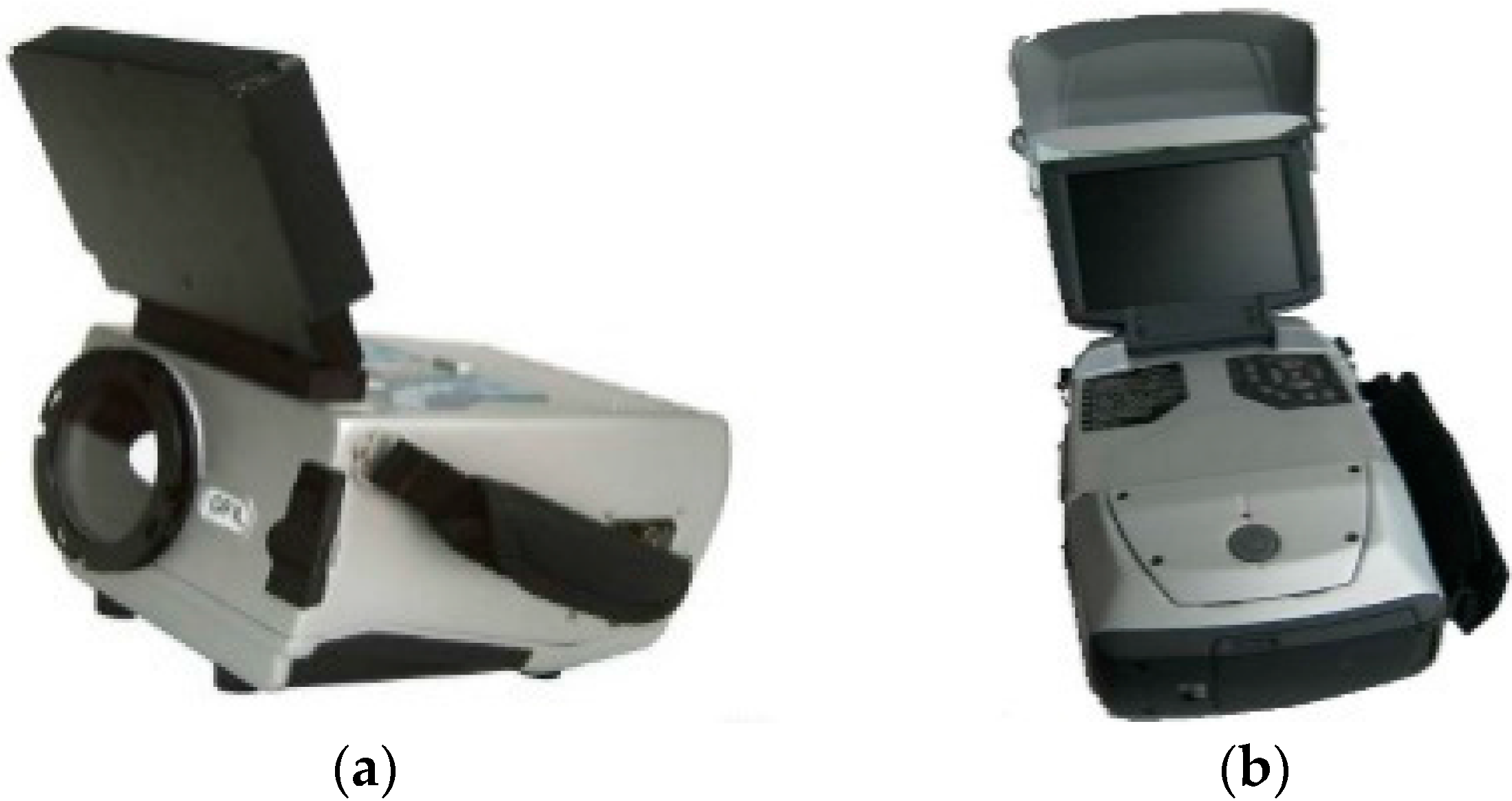
DayCor®Superb (Type A, made by OFIL, Tel Aviv-Yafo, Israel) and CoroCAM®6d (Type B, made by CSIR, Cape Town, South Africa) UV imagers were used in the experiments, as shown in Figure 3. The basic parameters of the UV imagers are shown in Table 1.
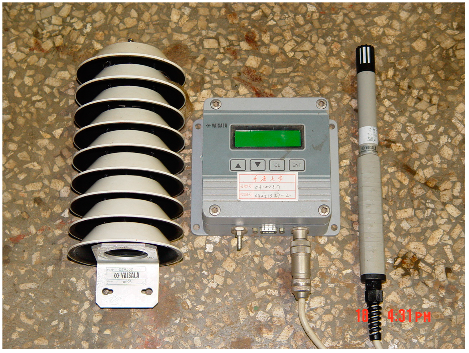
The atmospheric pressure (p), temperature (T) and relative humidity (RH) in the experiments were measured with a PTU2000 device (VAISALA, Helsinki, Finland) as shown in Figure 4. At 20 °C, the temperature measurement error is ±0.2 °C, and the relative humidity error is ±1%.

2.2. Test Specimens

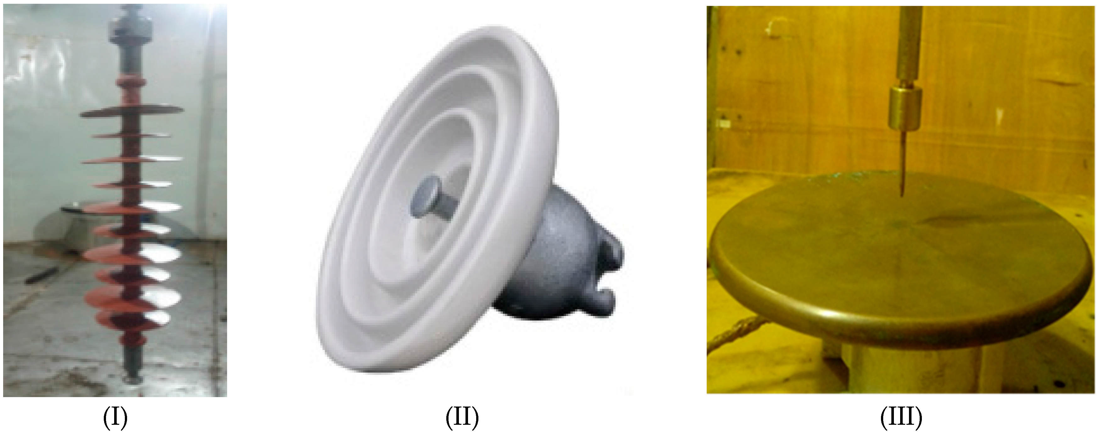
The experimental specimens were FXBW-35/70 composite insulators (I) (HONGGUANG, Leqing, China), XP-70 porcelain insulators (II) (HAOTIANTONG, Hejian, China), and a needle-plane model (III) (Chongqing University, Chongqing, China), as shown in Figure 5. The basic technical parameters of the insulators are shown in Table 2. The curvature radius of the needle-plane model tip is 0.1 mm, the plane electrode diameter is 60 mm (made of brass plate), and the air gap of .needle-plane model is 15 mm.

2.3. Test Procedures

The surface of the specimens was kept clean and dry to avoid the effects of pollution and water drop discharge during the experiments. The test procedures were as follows.
(1)
Sample III was used to study the relationship between photon number and discharge magnitude. It was arranged as shown in Figure 2. Before the experiment, the signal source was injected into the insulator with 1000, 500, and 100 pC discharge magnitude. Then, the scale factor of discharge magnitude (kc) was calculated, and the partial discharge measurement system was calibrated. In the test, the UV video signal and discharge signal were recorded synchronously.
(2)
In other tests, the experimental specimens were arranged according to Figure 2 without measurement of discharge magnitude. p, T and RH were set to fixed values for the same experiments and samples, and the range of observation distance between the specimens and UV imagers was 0 to 25 m.
(3)
The UV imager gains were adjusted from small to large in their respective span.
(4)
The applied voltage of specimens was gradually increased to a predetermined voltage, and corona discharge was detected and orientated by the UV imagers.
(5)
A lighting spot will found on the screen of UV imager, then we start shooting a video of the discharge when the image is steady; every video lasts about 30 s.
(6)
According to the preceding test procedures, several photon numbers of corona discharge detection were obtained for the same test condition. By deleting data that are 15% higher or lower than the mean value, the average value of valid photon numbers can be retained and then selected as the final detection result under a certain condition.

3. Relationship between Photon Number and Discharge Magnitude

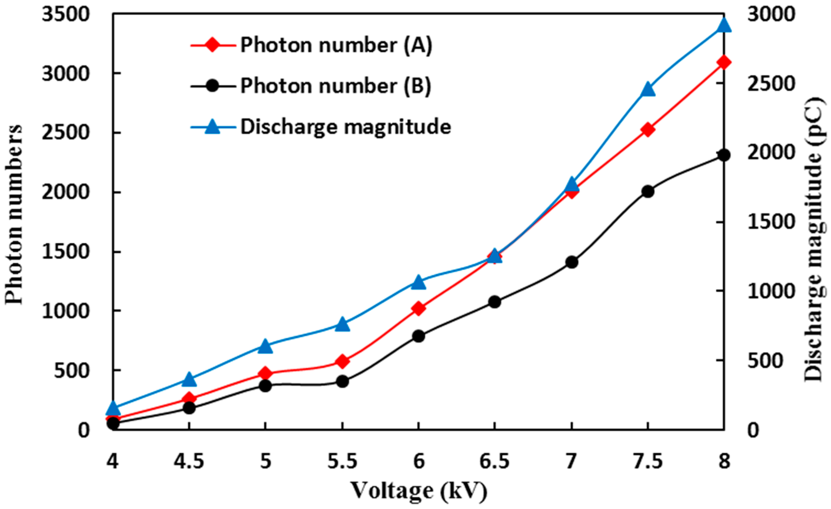
Discharge magnitude is a characteristic parameter that can effectively quantify insulator discharge. Sample III was used to study the relationships between different UV imagers and discharge magnitude; the observation distance was 6 m. Test results are shown in Figure 6.
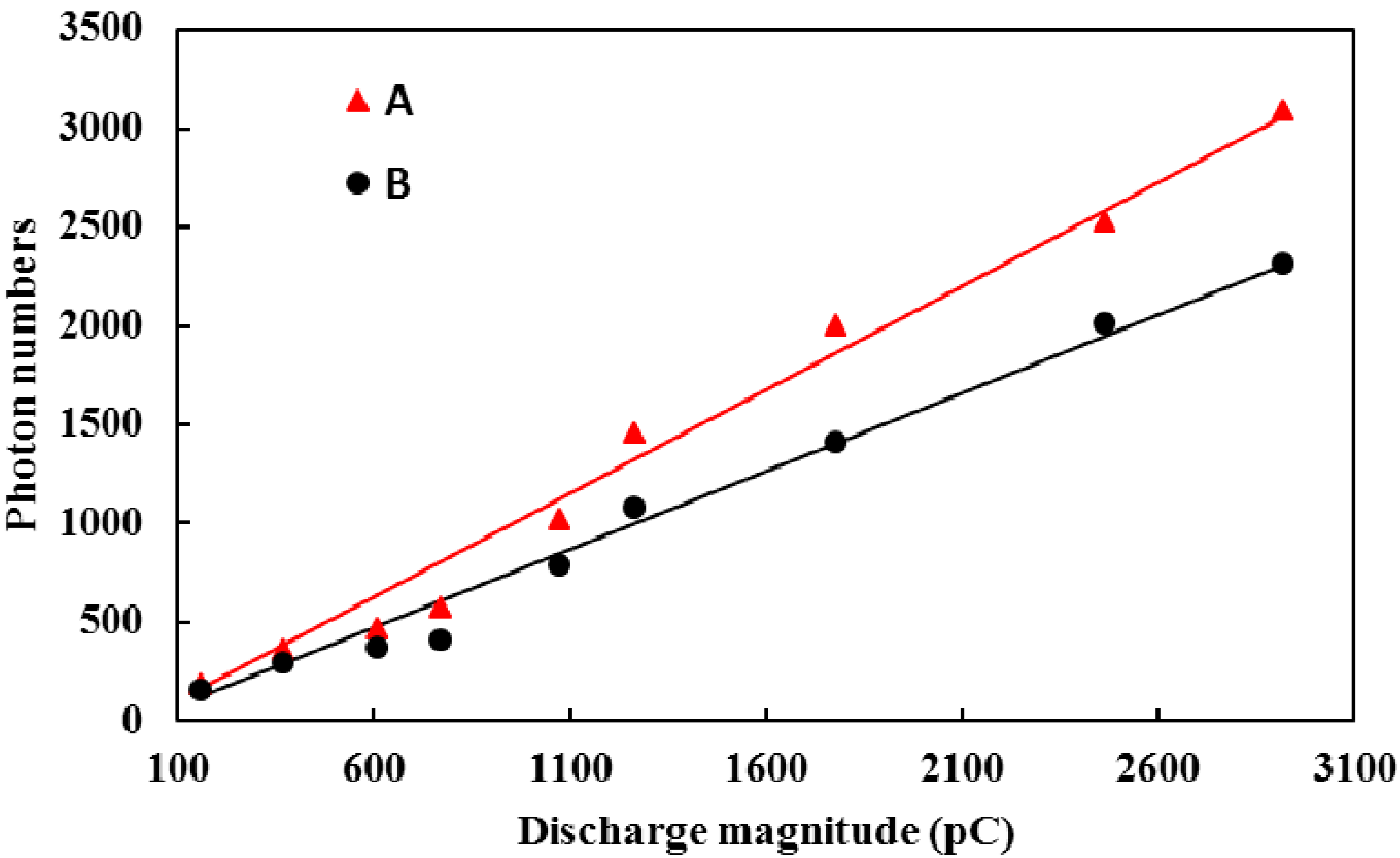
As shown in Figure 6, photon numbers from the two UV imagers and discharges increase with increased voltage. The curves in Figure 6 have similar trends. Furthermore, the relationship between photon number and discharge magnitude of different UV imagers is similar. Hence, photon number could be used as a UV detection result to represent corona discharges. To study the relationship between photon number and discharge magnitude, the curves relating photon number and discharge magnitude are shown in Figure 7.
Figure 7 shows that the photon numbers from different imagers and discharge magnitudes have nearly linear relationships. Hence, photon number could indicate insulation discharge. Therefore, the discharge magnitude of corona discharge could be represented by photon number, and it is feasible to use photon number to study corona discharges.

4. Test Results and Analyses

4.1. Influence of Observation Angle

To determine whether the discharge detection of a UV imager is affected by observation angle, Types A and B UV imagers were used to detect the corona discharge of sample I at the same observation distance. The UV imagers were moved from the front of the discharge position to the side at the same observation distance (6 m). The test results are shown in Table 3.
It can be found from Table 3 that regardless of the selected imager gain, the corona discharge detection photon numbers of both Types A and B UV imagers obtained from the front view are basically equal to those from the other views. The errors between the maximum and minimum photon numbers are less than 5%. These errors may have originated from the interference during the measurements. The UV imagers were moved from the front to the side in accordance with the circle in the test process. The photon numbers basically change around the average value, and the variations are negligible and can be ignored. Hence, if obstructions or interference sources exist in the front of the discharge position, a UV imager can change to other angles to keep away from certain obstructions or interferences. Comparison of the results of the front view implies that the detection results of the two UV imagers are basically the same. The accuracy of discharge detection is unaffected. Therefore, the influence of observation angle on photon numbers is little in the detection, so it is not considered in the following tests and analysis.

4.2. Influence of Imager Gain

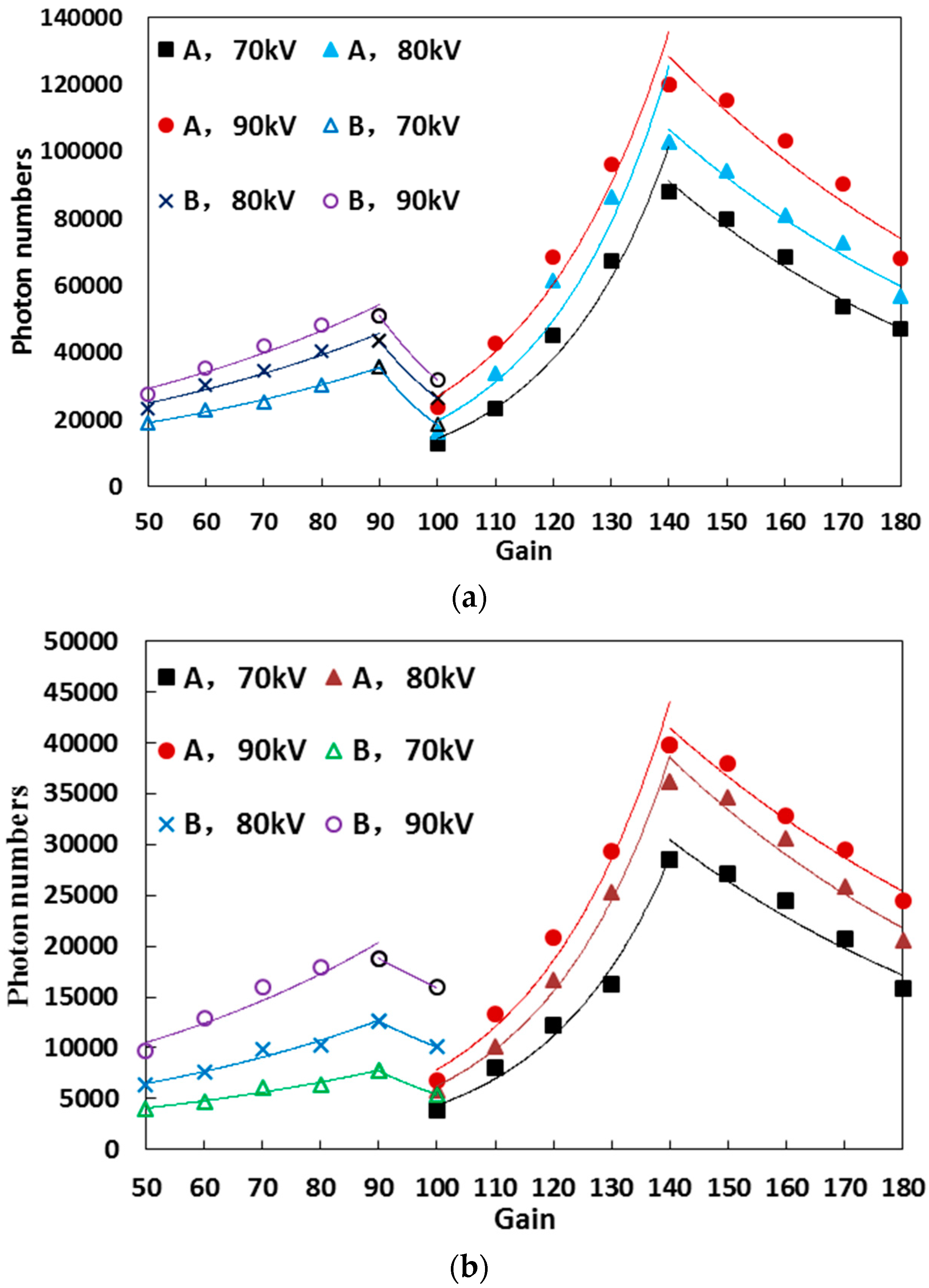
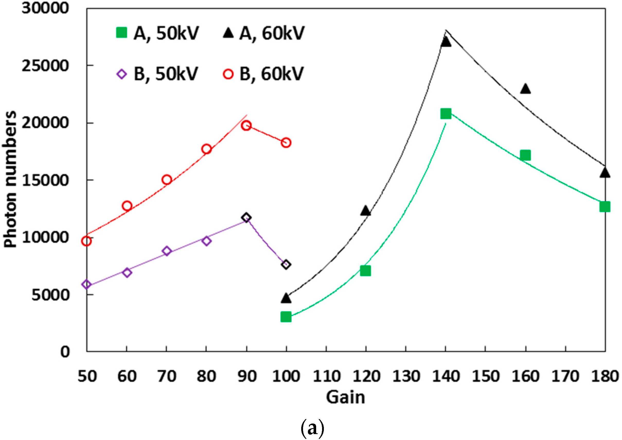
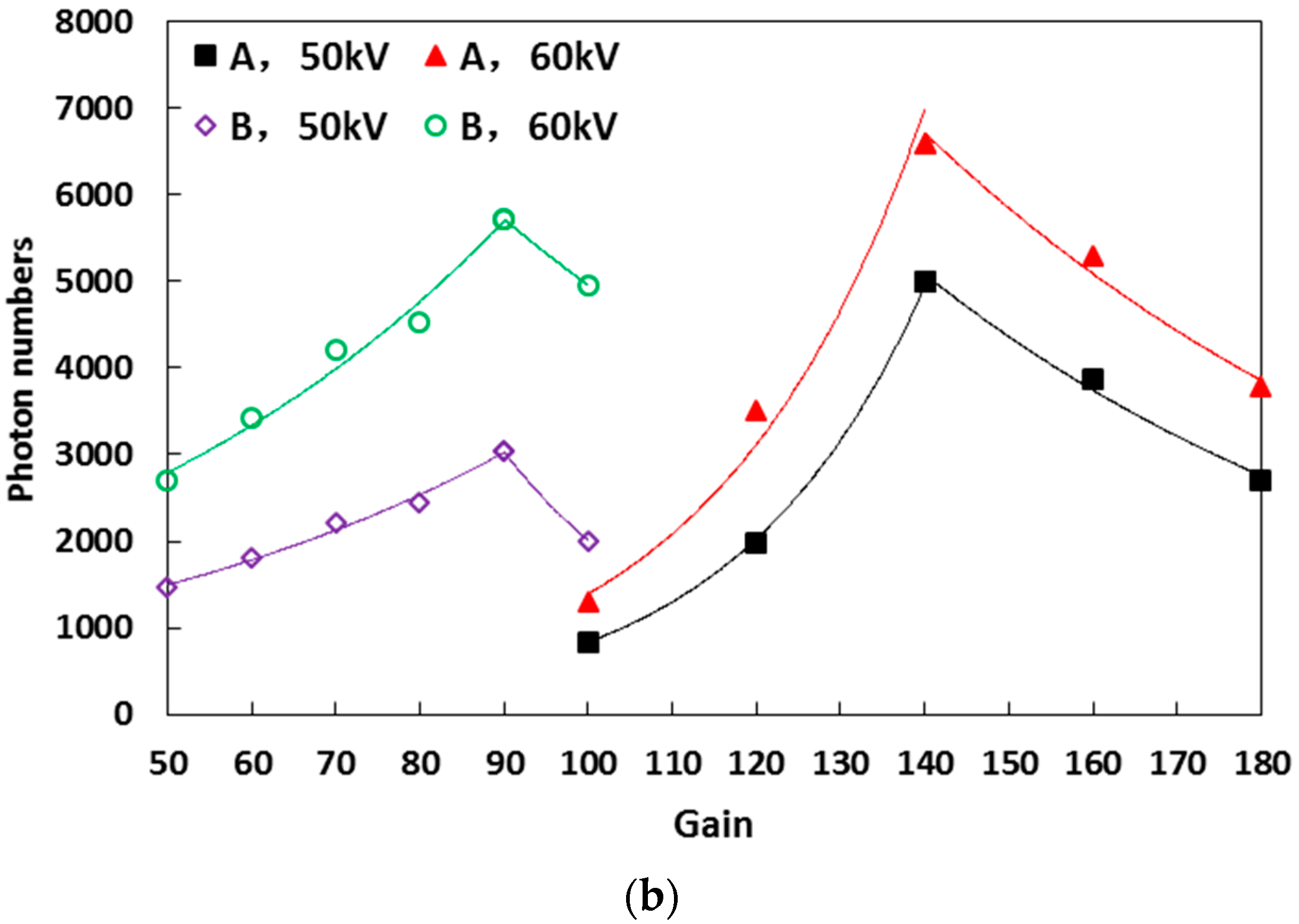
The detection results when the UV imagers were utilized are obviously affected by the variation in imager gain. Although the imager gain is the same, the differences in the UV imagers can affect the test results. Hence, the environmental parameters of the multifunctional artificial-climate chamber were controlled, and the observation distances were set to 6 and 12 m. Experiments were conducted to determine the influence of imager gains on corona discharge photon numbers under different applied voltages. Types A and B UV imagers were used to investigate samples I and II. The results are shown in Figure 8 and Figure 9, where d is the observation distance.
It can be obtained from Figure 8 and Figure 9 that although the observation distances are different, the influence of imager gains on the photon numbers of the two UV imagers presents the same trend in both samples I and II. Under different discharge intensities, the gain that corresponds to the peak of the photon numbers is considered the boundary. The detection photon numbers of the two imagers first increase and then decrease with the raise of imager gains. The gain that corresponds to the maximum photon numbers of Type A is approximately 140, whereas that of Type B is 90.
With increasing imager gain after the gain that corresponds to the peak of photon numbers, the photons of UV imaging diffuse patchy sources from point sources. This phenomenon causes the distortion of arc length in the detection and results in the misjudgment of discharge development. When the UV imagers are set to the gain that corresponds to the maximum photon numbers, they are considerably affected by outside interference. Hence, noise reduction should be implemented. Imager gain should reduce 10% of the gain range on the basis of the value that corresponds to the maximum photon numbers. When the gain is 120, Type A has a clear point source imaging, and patchy sources can be observed. Thus, 120 is the optimal gain of Type A. By contrast, the optimal gain of Type B is 80.
Figure 8 and Figure 9 also indicate that the variation trend of photon numbers with gain can be approximately expressed as an exponential function in increasing and decreasing intervals. However, owing to the large amount of outside interference, the quality of imaging from Type B is poor and unstable when the imager gain is greater than 90. Thus, the results under the gain of Type B over 90 are not recommended, and the variation trend of photon numbers with gain is irrespective when the gain is greater than 90. The test results were fitted according to Equation (1). The fitting results are shown in Table 4 where R2 is the square of fitting coefficients:
y = α e β g
In Equation (1), α and β are coefficients; g is the imager gain, and y is the photon number.
Table 4 provides the following findings:
(1)
The fitting degree R2 of each sample at different voltages is greater than 0.9. It means that the relationship between the photon number and imager gain of the two imagers can be expressed as an exponential function in increasing and decreasing intervals of imager gain.
(2)
The coefficients β of Types A and B UV imagers are approximately stable. Therefore, the relationship between photon number and gain has an approximate variable characteristic under different discharges. Equations (2) and (3) accord with the relationship of photon numbers with the gains of Types A and B UV imagers, respectively:
y = { α e 0.0448 g   ( g 140 ) α e 0.0140 g   ( g > 140 )
y = α e 0.0166 g   ( g 90 )
where α is a coefficient, g is the imager gain, and y is the photon number.
(3)
Correction of detection photon numbers under different gains can be realized by Equations (2) and (3). The photon numbers of Types A and B UV imagers can be corrected from different gains to optimal gains by Equations (4) and (5), respectively:
y = { y 1 e 0.0448 ( 120 g )   ( g 140 ) y 1 e 0.0140 ( g 780 )   ( g > 140 )
y = y 1 e 0.0166 ( 80 g )   ( g 90 )
where y1 is the measurement photon numbers, g is the imager gain, and y is the photon numbers corrected to optimal gains.

4.3. Relation of Observation Distance to Photon Numbers

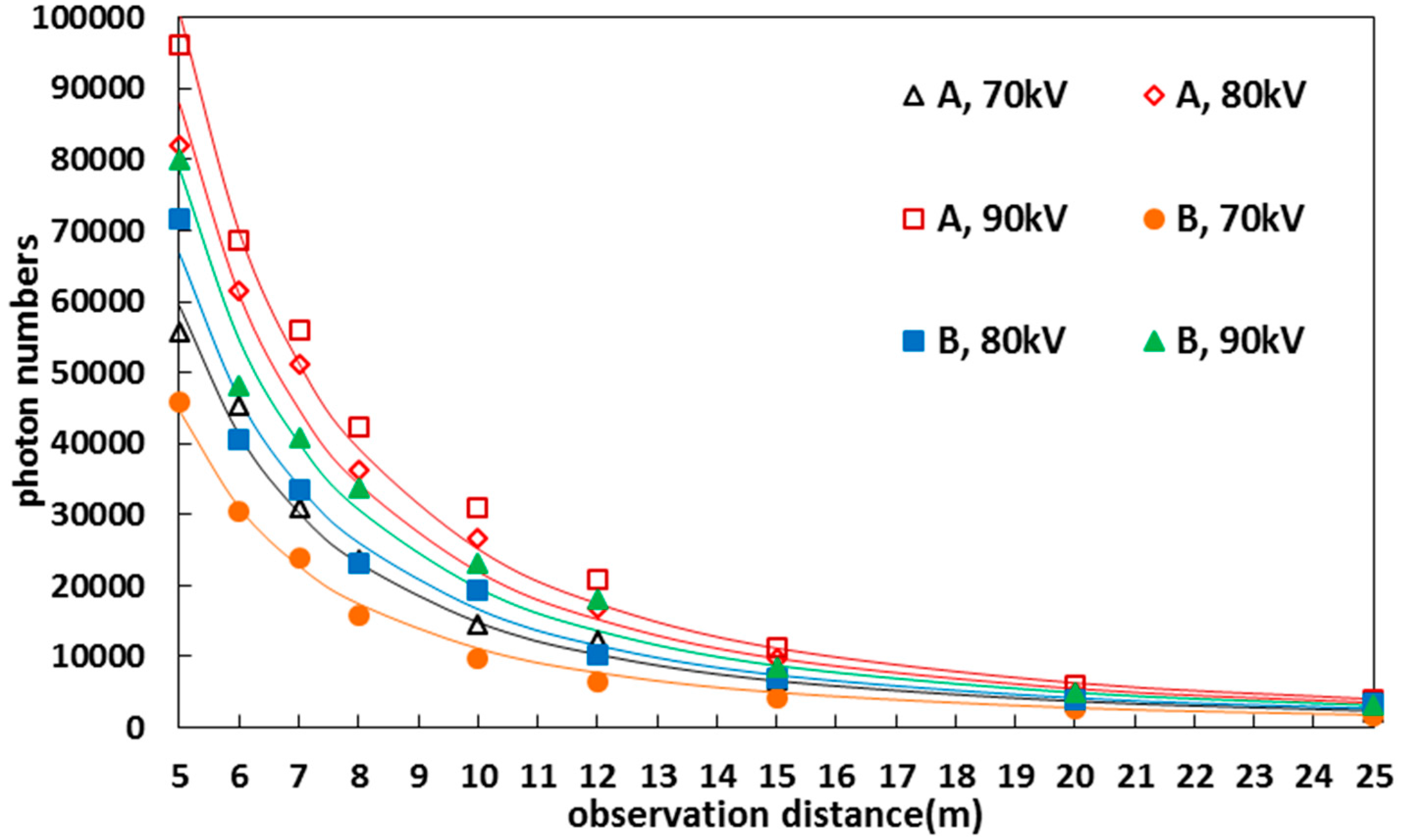
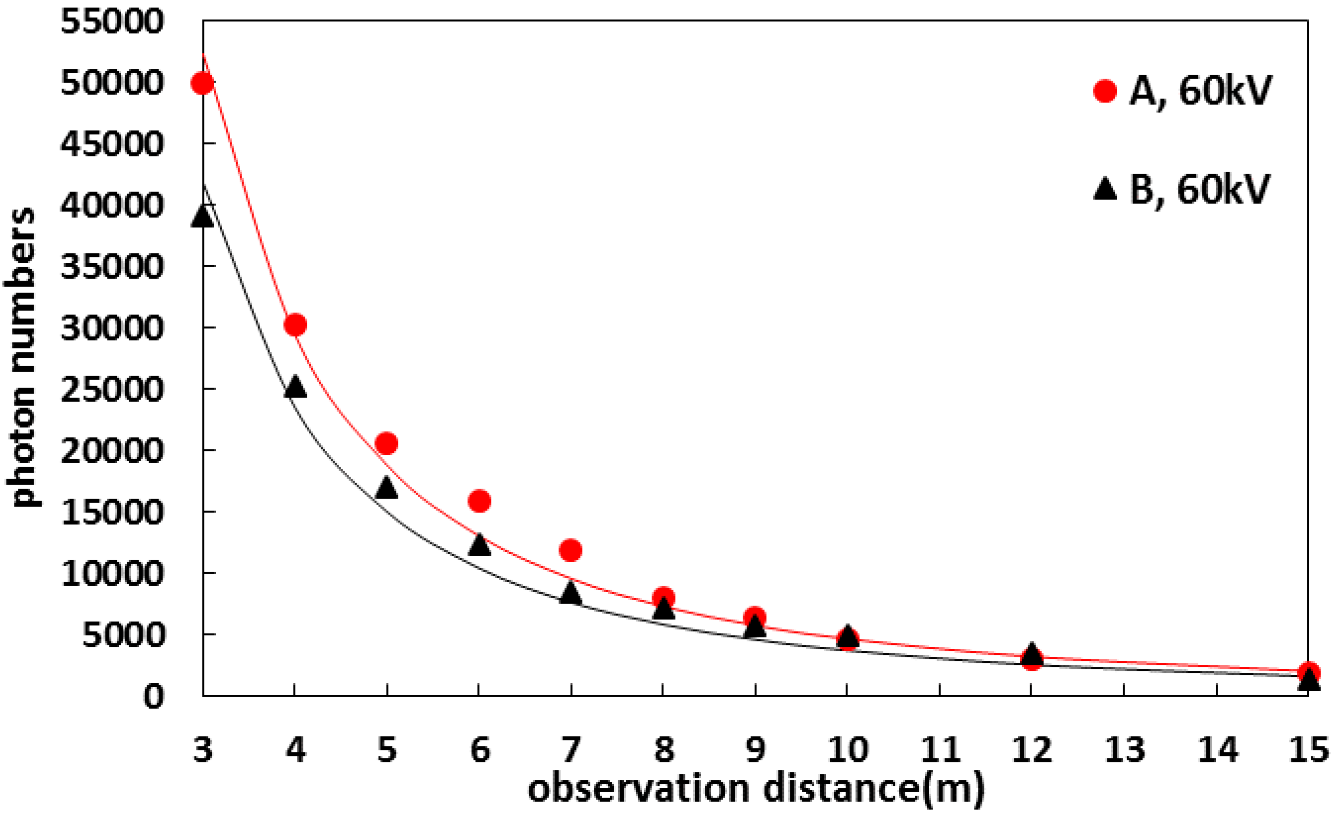
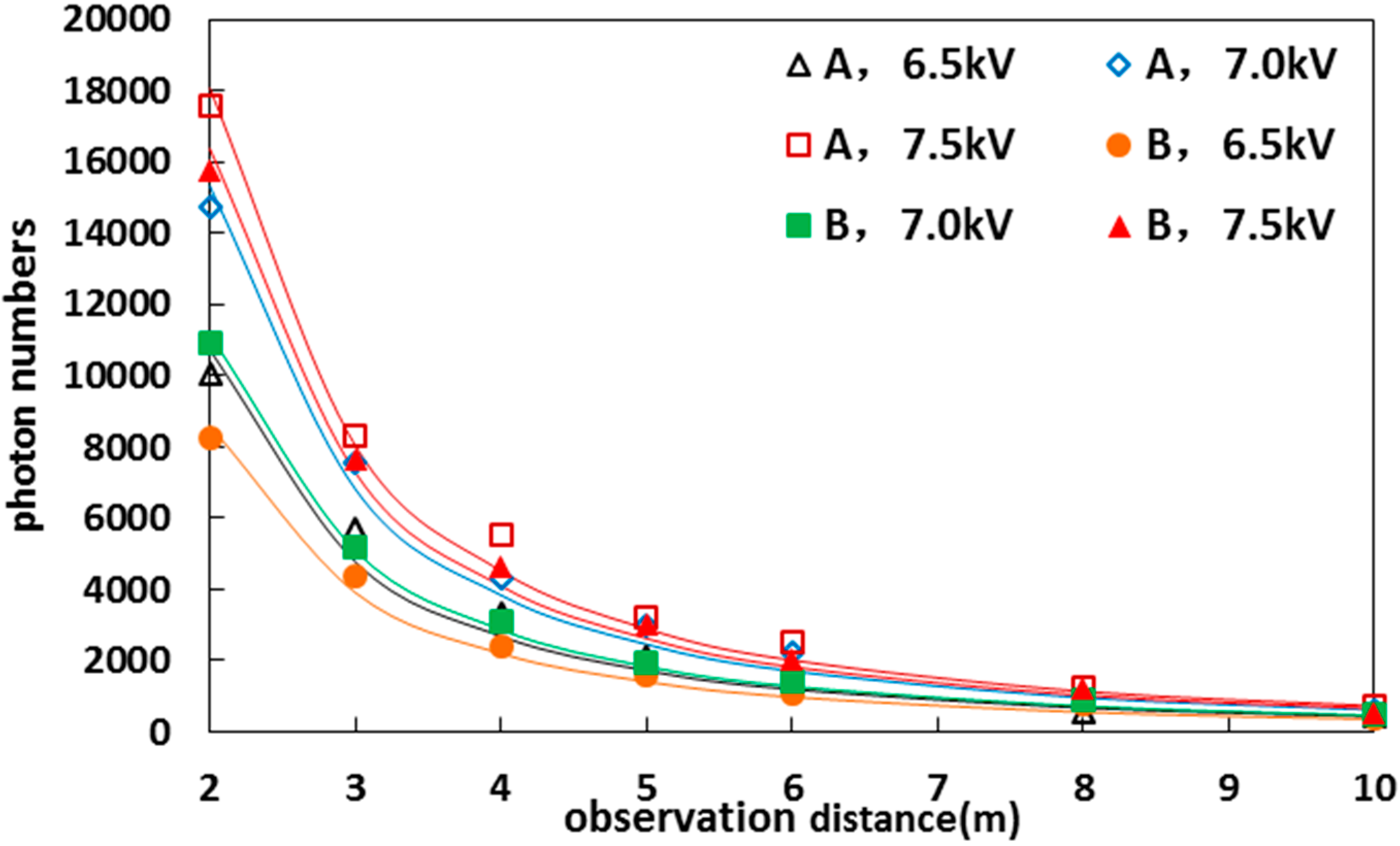
Environmental parameters were controlled in the multifunctional artificial-climate chamber. The imager gain of Type A was set to an optimal value of 120, and the imager gain of Type B was set to 80. Tests were conducted for samples I–III to identify the influence of observation distance on photon numbers. The test results are shown in Figure 10, Figure 11 and Figure 12.
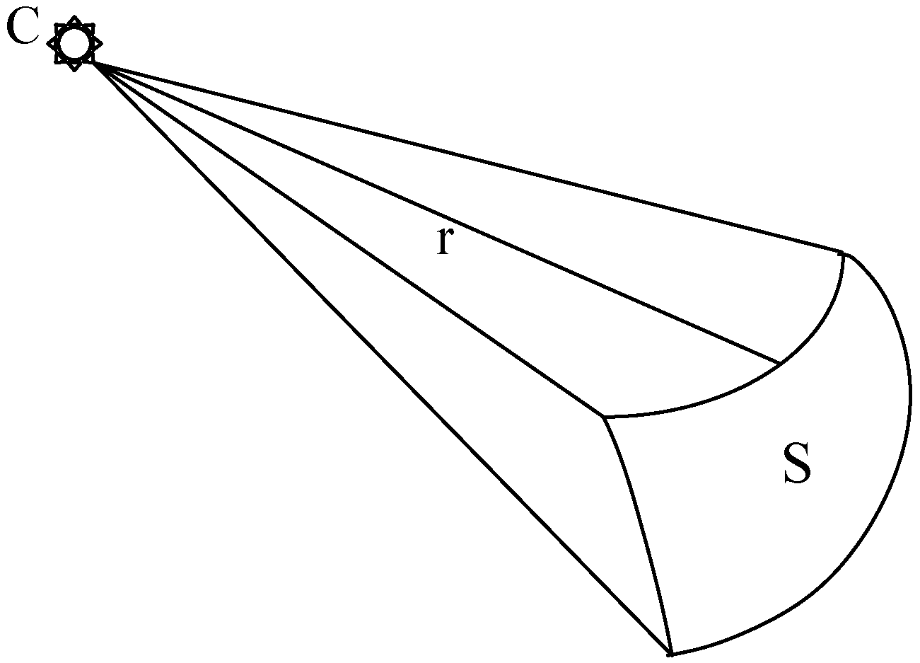
Corona discharge can be regarded as a point source, and a UV imager is utilized to detect the corona discharge by a UV signal. Therefore, C is the light source, and S is the spherical area with a radius of r, as shown in Figure 13.
The irradiation intensity of C is Q, the luminous flux surface density of S from C is ρ, and the light intensity of S is L. ρ and L can be expressed as follows:
ρ = Q 4 π r 2
L = ρ × S = Q 4 π r 2 × S = Q S 4 π r 2
Equation (7) indicates that the light signal parameters (photon number) decrease with the increase in the square of the observation distance. Thus, the relationship between observation and observation distance can be expressed as follows:
y = a d 2
where a is a coefficient, d is the observation distance, and y is the photon number. The test results were fitted in accordance with Equation (8). The fitting results are shown in Table 5, where R2 is the square of fitting coefficients.
In Table 5, the fitting degree R2 of each sample at different voltages is close to 1. The relationship between observation distance and photon number satisfies Equation (8). Thus, the measurement results of different distances should be corrected.
If d0 is the reference distance, then the correction equation of different observation distances can be expressed as follows:
y = y 1 ( d d 0 ) 2
where, y1 is the measurement photon number in actual observation distance, d is the observation distance, and y is the photon number that has been corrected to the reference distance (the ideal reference distance is 10 m in study).

4.4. Correction of Different Imager

Based on the research of previous sections, it is found that the test results of different types of UV imagers are inconsistent under the same conditions. This inconsistency is caused by the differences in imager internal structure and components. In this case, correction between different types of imagers is significant in power system applications.
Similarly, the two UV imagers were used in the detection of corona discharge with the same samples under the same conditions. The gains of the two imagers were set to optimal values, and the test results are shown in Figure 10, Figure 11 and Figure 12. The photon numbers of the different types of imagers were corrected in accordance with the fitting results of Table 5. Correction coefficient K is expressed in Equation (10), and the correction results are provided in Table 6:
K = y A y B = α A α B
From Table 6, it can be found that correction coefficient K is approximately 1.3 under various situations, and the errors are less than 10%. Thus, correction coefficient K of Type A to B can be regarded as 1.3.

5. On-Site Test

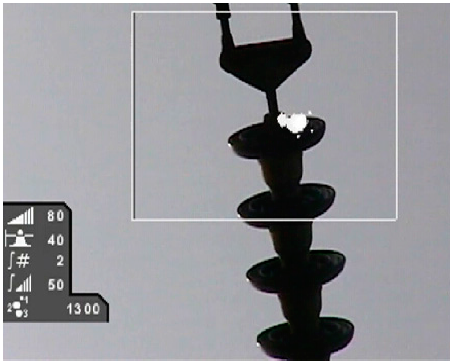
UV imagers were used in an on-site test, where the mentioned conclusions from the laboratory work were confirmed. Type A was tested in a 500 kV substation at Liping in China. In the substation, a strong corona discharge from the fixed contact was detected by the Type A device at different observation distances and different observation angles, as illustrated in Figure 14 and Table 7.
As shown in Table 7, the corona discharge photon numbers of the Type A instrument from the front view are basically equal to those from the other views. The errors between the maximum and minimum photon numbers are less than 5%. Therefore, the influence of obsevation angle is very limited. Photon numbers at different observation distances from Table 7 are fitted with Equation (8), and the fitting accuracy is very high, R2 is 0.9827. Hence, the conclusion about the effect of obsevation diastance on the photon number can be used in the on-site test.
The Type B device was tested in a 500 kV substation at Pingguo in China to detect corona discharge of the insulator, as shown in Figure 15 and Table 8.
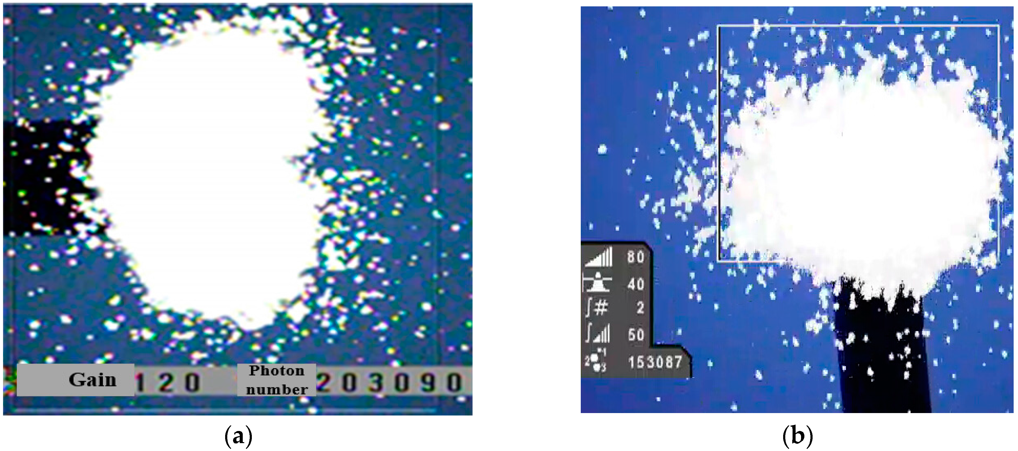
Photon numbers from Table 8 are fitted with Equation (8), and the fitting result is 0.9769. Therefore, the conclusion about observation distance of two UV imagers can be used in the on-site test. Photon numbers at different observation angles from Table 8 are basically equal. Hence, the conclusion about the effect of observation angle on the photon number of two UV imagers can be used in the on-site test. Types A and B were both used in a ±500 kV convertor station located at Zhaotong in China to detect corona discharges of the grading ring, as shown in Figure 16 and Table 9.
As shown in Table 9, K is about 1.3, hence, the test results match the laboratory conclusions. Based on the above detection in on-site tests, the conclusions of the laboratory experiments are confirmed.
6. Conclusions

Based on the tests of corona discharge, the following conclusions can be obtained:
(1)
The observation angle of UV imagers has little impact on UV detection if no obstacles block the line of detection sight.
(2)
The gain of UV imagers exerts an obvious influence on the photon number detection result of corona discharges. UV imagers have optimal imager gains in corona discharge detection. The optimal gains of Types A and B are 120 and 80 in this study, respectively. Therefore, in engineering practice, the optimal gain of a UV imager could be selected on the basis of the specific imager type. Detection results can be corrected to optimal gains in accordance with the gain correction formula.
(3)
The photon numbers of discharge detection decrease with the increase in the square of observation distance. The distance from the sample should be measured and corrected to the contrast distance in accordance with the correction method in this study after discharge detection.
(4)
The detection results of different UV imager types are different in corona discharge detection. Therefore, the photon numbers of different UV imager types should be corrected according to the correction coefficients for different UV imager types.

Acknowledgments

This work was supported by the Funds for Innovative Research Groups of China (No. 51321063). The authors thank all members of the external insulation research team in Chongqing University for their hard work to obtain the experimental data in this paper.

Author Contributions

Zhenyu Li contributed to the research idea and theoretical analysis, and drafted the manuscript. Licheng Li, Xingliang Jiang, Jianlin Hu, Zhijing Zhang, Wei Zhang worked on the revision of the manuscript. All authors have approved the final manuscript.

Conflicts of Interest

The authors declare no conflict of interest.

References

  1. Han, S.; Hao, R.; Lee, J. Inspection of insulators on high-voltage power transmission lines. IEEE Trans. Power Deliv. 2009, 24, 2319–2327. [Google Scholar] [CrossRef]
  2. Moreno, V.M.; Gorur, R.S. Impact of corona on the long-term performance of nonceramic insulators. IEEE Trans. Dielectr. Electr. Insul. 2003, 10, 80–95. [Google Scholar] [CrossRef]
  3. Sawada, J.; Kusumoto, K.; Maikawa, T. A mobile robot for inspection of power transmission lines. IEEE Trans. Power Deliv. 1991, 6, 309–315. [Google Scholar] [CrossRef]
  4. Phillips, A.J.; Childs, D.J.; Schneider, M.H. Water drop corona effects on full-scale 500 kV non-ceramic insulators. IEEE Trans. Power Deliv. 1999, 14, 258–265. [Google Scholar] [CrossRef]
  5. Gubanski, S.M.; Dernfalk, A.; Andersson, J. Diagnostic methods for outdoor polymeric insulators. IEEE Trans. Dielectr. Electr. Insul. 2007, 14, 1065–1080. [Google Scholar] [CrossRef]
  6. Guo, J.; Wu, G.L.; Zhang, X.Q. The actuality and perspective of partial discharge detection techniques. Trans. China Electrotech. Soc. 2005, 20, 29–35. (In Chinese) [Google Scholar]
  7. Wang, S.H. Detection and Assessment of Contaminated Suspension Insulator Discharge Based on Ultraviolet Imaging. Ph.D. Thesis, North China Electric Power University, Baoding, China, 2012. [Google Scholar]
  8. Linders, M.; Elstein, S.; Linders, P.; Phillips, T.A.J. Daylight corona discharge imager. In Proceedings of the Eleventh International Symposium on High Voltage Engineering, London, UK, 23–27 August 1999; Volume 4, pp. 349–352.
  9. Stergis, C.G. Atmospheric transmission in the middle ultraviolet. In Proceedings of the Society of Photo-Optical Instrumentation Engineers (SPIE) Conference Series, San Diego, CA, USA, 1 August 1986; pp. 2–10.
  10. Mazzeo, G.; Reverchon, J.-L.; Duboz, J.-Y.; Dussaigne, A. AlGaN-based linear array for UV solar-blind imaging from 240 to 280 nm. IEEE Sens. J. 2006, 6, 957–963. [Google Scholar] [CrossRef]
  11. Kim, Y.; Shong, K. The characteristics of UV strength according to corona discharge from polymer insulators using a UV sensor and optic lens. IEEE Trans. Power Deliv. 2011, 26, 1579–1584. [Google Scholar] [CrossRef]
  12. Pinnangudi, B.; Gorur, R.S. Quantification of corona discharges on non-ceramic insulators. IEEE Trans. Dielectr. Electr. Insul. 2005, 12, 513–523. [Google Scholar] [CrossRef]
  13. Bologna, F.F.; Reynders, J.P.; Britten, A.C. Corona discharge activity on a string of glass cap-and-pin insulators under conditions of light wetting, light non-uniform contamination. In Proceedings of the 2003 IEEE Bologna Power Tech Conference Proceedings, Bologna, Italy, 23–26 June 2003; Volume 3, p. 8.
  14. Da Costa, E.G.; Ferreira, T.V.; Neri, E.G.G.; Queiroz, I.B. Characterization of polymeric insulators using thermal and UV imaging under laboratory conditions. IEEE Trans. Dielectr. Electr. Insul. 2009, 16, 985–992. [Google Scholar] [CrossRef]
  15. Zhou, W.J.; Li, H.; Yi, X.; Tu, J. A criterion for UV detection of AC corona inception in a rod-plane air gap. IEEE Trans. Dielectr. Electr. Insul. 2011, 18, 232–237. [Google Scholar] [CrossRef]
  16. Xiao, M.; Wen, C. New method to detect insulation on line ultraviolet image method. High Volt. Eng. 2006, 32, 42–44. (In Chinese) [Google Scholar]
  17. Zang, C.; Zhao, X.; He, S.; Lei, H. Research on mechanism and ultraviolet imaging of corona discharge of electric device faults. In Proceedings of the Conference Record of the 2008 IEEE International Symposium on Electrical Insulation, Vancouver, BC, Canada, 9–12 June 2008; pp. 690–693.
  18. Shong, K.M.; Kim, Y.S.; Kim, S.G. Images detection and diagnosis of corona discharge on porcelain insulators at 22.9 kV. In Proceedings of the IEEE International Symposium on Diagnostics for Electric Machines, Power Electronics and Drives, Cracow, Poland, 6–8 September 2007; pp. 462–466.
  19. Pinnangudi, B.; Gorur, R.S.; Kroese, A.J. Quantification of corona discharges on non-ceramic insulators. IEEE Trans. Dielectr. Electr. Insul. 2005, 12, 513–523. [Google Scholar] [CrossRef]
  20. Wang, S.H.; Lv, F.C.; Liu, Y.P. Estimation of discharge magnitude of composite insulator surface corona discharge based on ultraviolet imaging method. IEEE Trans. Dielectr. Electr. Insul. 2014, 21, 1697–1704. [Google Scholar] [CrossRef]
Figure 1. Experimental facilities (a) 500 kV/2000 kVA testing transformer; (b) multifunctional artificial-climate chamber; (c) 500 kV capacitive voltage divider.
Energies 09 00369 g001
Figure 2. Schematic of the test circuit. T: 10 kV voltage regulator; B: testing AC transformer; R1, Rm: protective resistance; F: AC capacitive voltage divider (10,000:1); R2: detection impedance; H: oscilloscope.
Energies 09 00369 g002
Figure 3. Ultraviolet (UV) imagers. (a) Type A; (b) Type B.
Energies 09 00369 g003
Figure 4. PTU2000.
Figure 4. PTU2000.
Energies 09 00369 g004
Figure 5. Experimental specimens. (I) FXBW-35/70; (II) XP-70; (III) needle-plane model.
Energies 09 00369 g005
Figure 6. Test results of photon numbers and discharge magnitude (p = 97.98 kPa; T = 20.3 °C; RH = 62.7%).
Energies 09 00369 g006
Figure 7. Relationship between photon number and discharge magnitude.
Energies 09 00369 g007
Figure 8. Influence of imager gains on corona discharge photon numbers for sample I (p = 98.09 kPa; T = 20 °C; RH = 78.2%). (a) d = 6 m; (b) d = 12 m.
Energies 09 00369 g008
Figure 9. Influence of imager gains on corona discharge photon numbers for sample II (p = 97.93 kPa; T = 24.5 °C; RH = 59.1%). (a) d = 6 m; (b) d = 12 m.
Energies 09 00369 g009aEnergies 09 00369 g009b
Figure 10. Influence of observation distance on photon numbers for sample I (p = 98.09 kPa; T = 20 °C; RH = 78.2%).
Energies 09 00369 g010
Figure 11. Influence of observation distance on photon numbers for sample II (p = 97.93 kPa; T = 24.5 °C; RH = 59.1%).
Energies 09 00369 g011
Figure 12. Influence of observation distance on photon numbers for sample III (p = 98.02 kPa; T = 22.3 °C; RH = 70.4%).
Energies 09 00369 g012
Figure 13. Schematic of light source.
Energies 09 00369 g013
Figure 14. Detection image of Type A in the on-site test.
Energies 09 00369 g014
Figure 15. Detection image of Type B in the on-site test.
Energies 09 00369 g015
Figure 16. Detection image. (a) Type A; (b) Type B.
Energies 09 00369 g016
Table 1. Basic parameters of the ultraviolet (UV) imagers.
TypeVisual AngleSensitivity (W/cm2)Range of Imager Gain
A5° × 3.75°3 × 10−120–250
B8° × 6°3 × 10−180–100
Table 2. Basic Parameters of the Insulators.
TypeStructure Height (mm)Creepage Distance (mm)Shed Diameter (mm)
FXBW-35/707201600148/118
XP-70146280255
Table 3. Detection results under different observation angles (p = 98.09 kPa; T = 20 °C; RH = 78.2%).
Voltage (kV)Imager TypeImager GainPhoton Numbers
Front View45° Angle90° Angle
70A12045,28746,10645,887
13070,38069,17869,908
14088,85187,84389,107
B7025,67924,88425,937
8029,23929,60228,637
9031,50532,50032,005
80A12061,63461,31561,949
13086,30687,38285,324
14096,82698,68197,694
B7036,52135,94737,068
8039,86738,51240,379
9040,63141,74541,376
90A12068,49069,47368,017
13096,00298,03697,038
140116,946112,949114,997
B7049,04149,94348,098
8050,08650,76349,323
9051,10350,94452,047
Table 4. Fitting parameters of imager gains to photon numbers.
SamplesDistance (m)Imager TypeRange of Imager GainVoltage (kV)αβR2
I6A≤14070107.60.04890.9725
≤14080190.10.04640.9386
≤14090467.50.04050.9676
>14070909,775−0.01600.9800
>14080805,813−0.01400.9672
>14090976,830−0.01400.9078
B≤907087470.01560.9939
≤908011,6090.01520.9574
≤909013,4970.01550.9479
12A≤1407038.70.04720.9765
≤1408065.60.04560.9928
≤14090105.60.04310.9724
>1407022,517−0.01400.9187
>14080283,423−0.01400.9426
>14090229,768−0.01200.9967
B≤901801808.40.01620.9679
≤902002796.30.01680.9686
≤902204602.30.01650.9220
II6A≤1405025.10.04770.9945
≤1406060.30.04380.9964
>14050118,554−0.01200.9835
>14060192,401−0.01400.9499
B≤90502549.30.01700.9867
≤90604261.50.01750.9746
12A≤140509.70.04460.9996
≤1406024.60.04030.9835
>1405043,257−0.01500.9900
>1406046,905−0.01400.9835
B≤9050618.70.01760.9908
≤906011440.01780.9784
Table 5. Fitting parameters of observation distance to photon numbers.
SpecimensImager TypeVoltage (kV)aR2
IA701.484 × 1060.9884
802.197 × 1060.9831
902.516 × 1060.9877
B701.116 × 1060.9926
801.668 × 1060.9812
901.966 × 1060.9731
IIA604.709 × 1050.9852
B603.766 × 1050.9815
IIIA6.54.292 × 1040.9729
7.06.131 × 1040.9894
7.57.230 × 1040.9915
B6.53.443 × 1040.9845
7.04.464 × 1040.9959
7.55.996 × 1040.9783
Table 6. Correction Coefficients of different UV imagers.
SampleVoltage (kV)K
I1601.330
1801.317
2001.280
II801.250
III6.51.247
7.01.373
7.51.206
Table 7. Photon numbers of Type A in the on-site test.
TypeObservation Distance (m)
9.410.613.717.722
A40,29031,44022,18013,0008250
AObservation Distance (m)Observation Angle
Front View45° Angle90° Angle
13.721,48022,28022,180
Table 8. Photon numbers of Type B in the on-site test.
TypeObservation Distance (m)
1313.916.419.823.9
B16811291967651501
BObservation Distance (m)Observation Angle
Front View45° Angle90° Angle
16.49671008982
Table 9. Test results.
TypeObsevation Diustance (m)
8.19.512.917
A203,980160,70099,12059,600
B153,693126,86574,26746,658
K1.3271.2671.3351.278