
Optimization of Shift Schedule for Hybrid Electric Vehicle with Automated Manual Transmission

Abstract
:1. Introduction
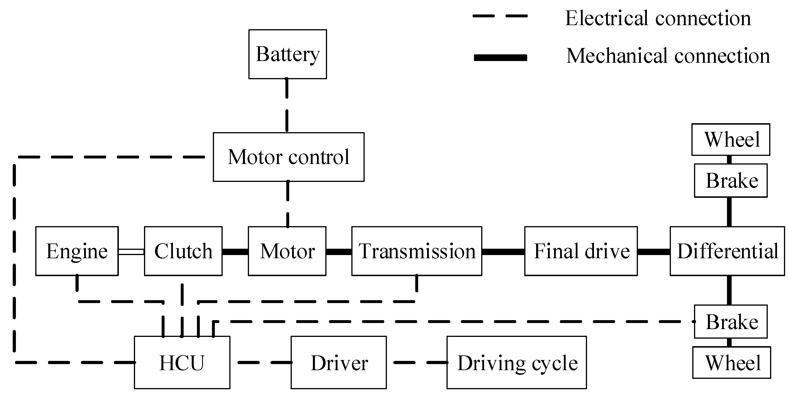
2. Modeling of the HEV
2.1. Engine Model
2.2. Clutch Model
2.3. Transmission Model
2.4. Motor Model
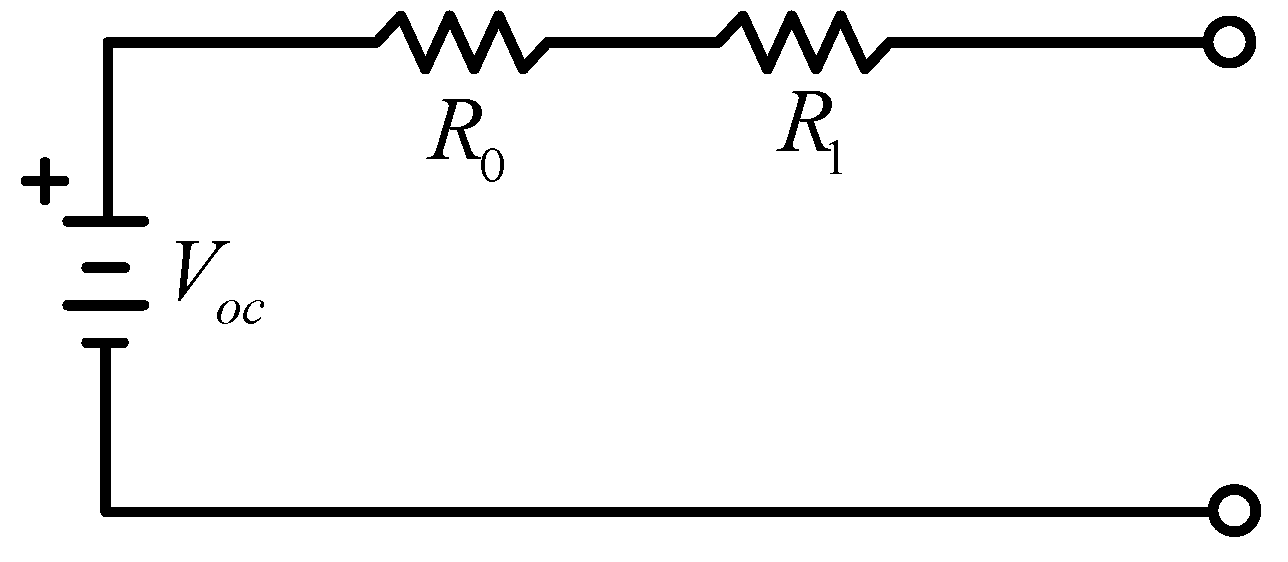
2.5. Battery Model
2.6. Longitudinal Dynamics of the HEV
3. Problem Formulation of the HEV Gear Shift Schedule
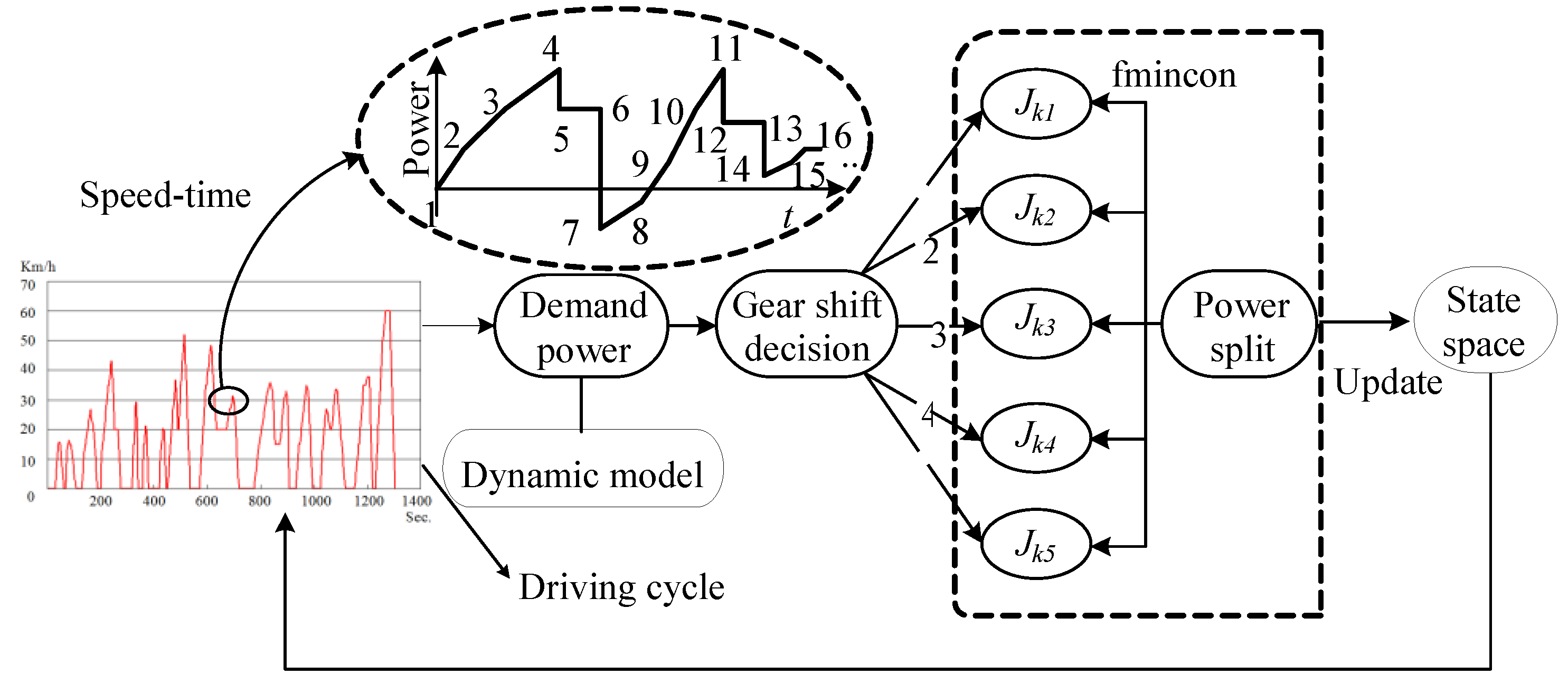
4. Solving Algorithm of the Optimization Problem
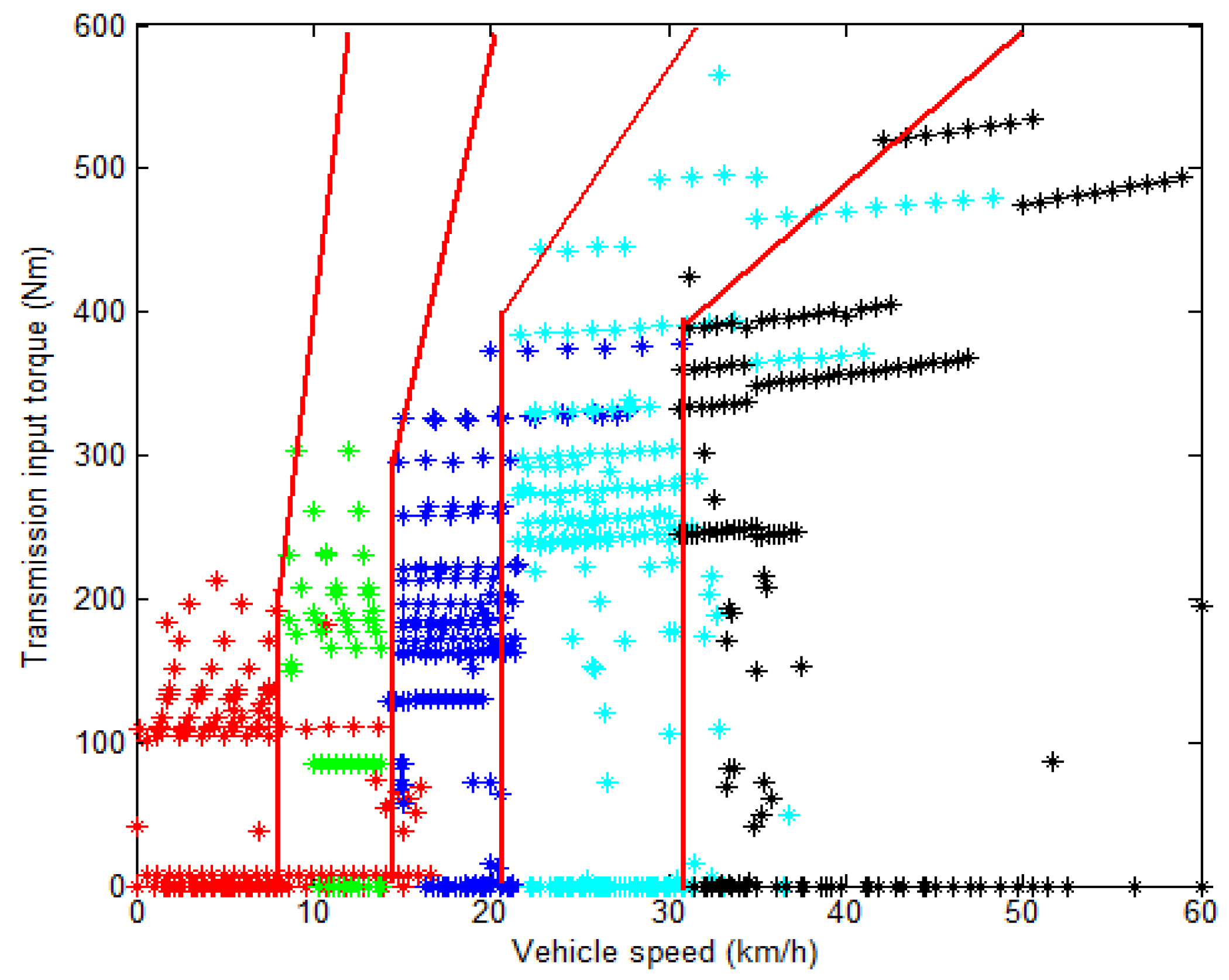
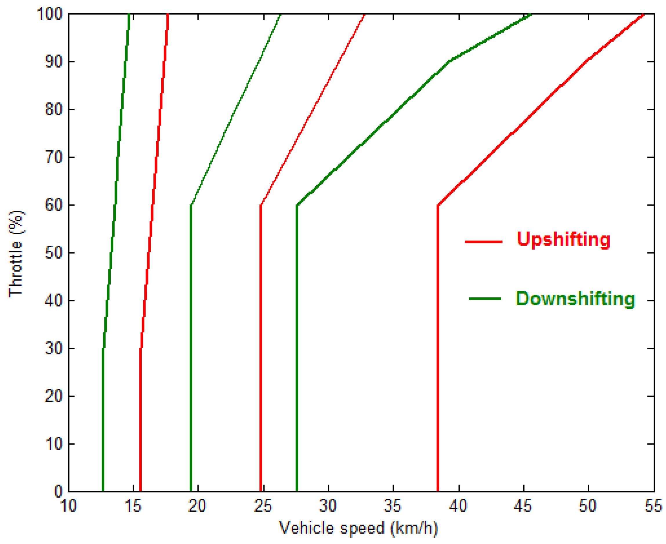
5. Extraction of the Implementable Gear Shift Schedule
6. Analysis of Simulation and Real Vehicle Test
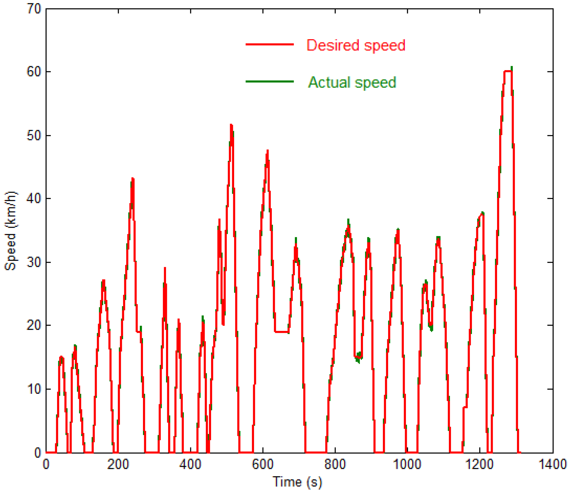
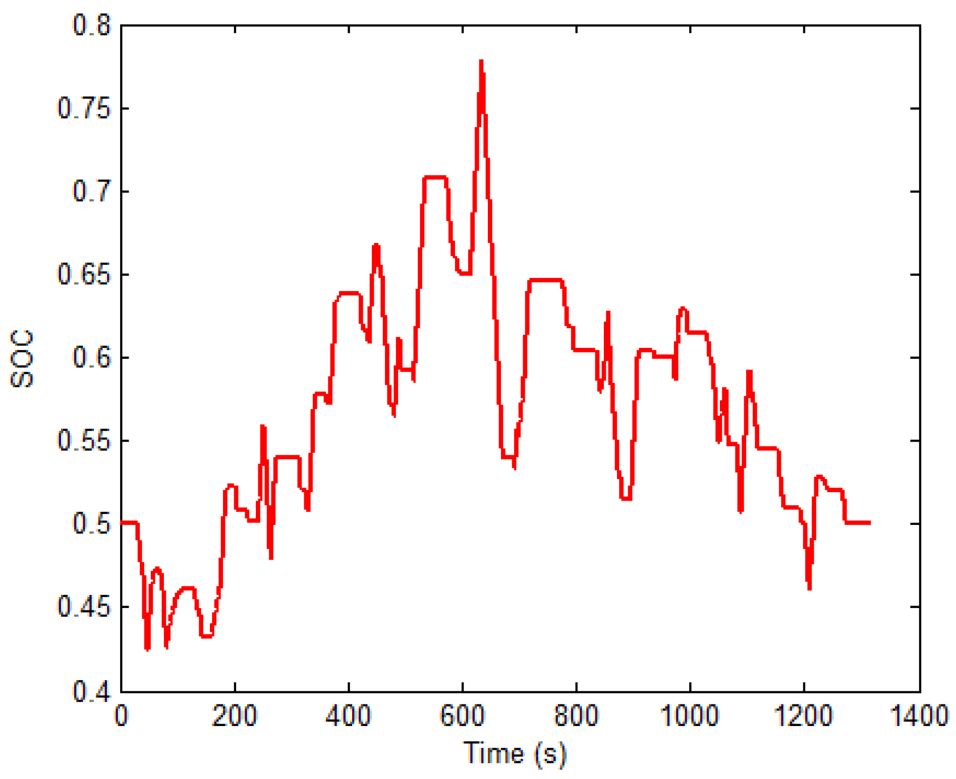
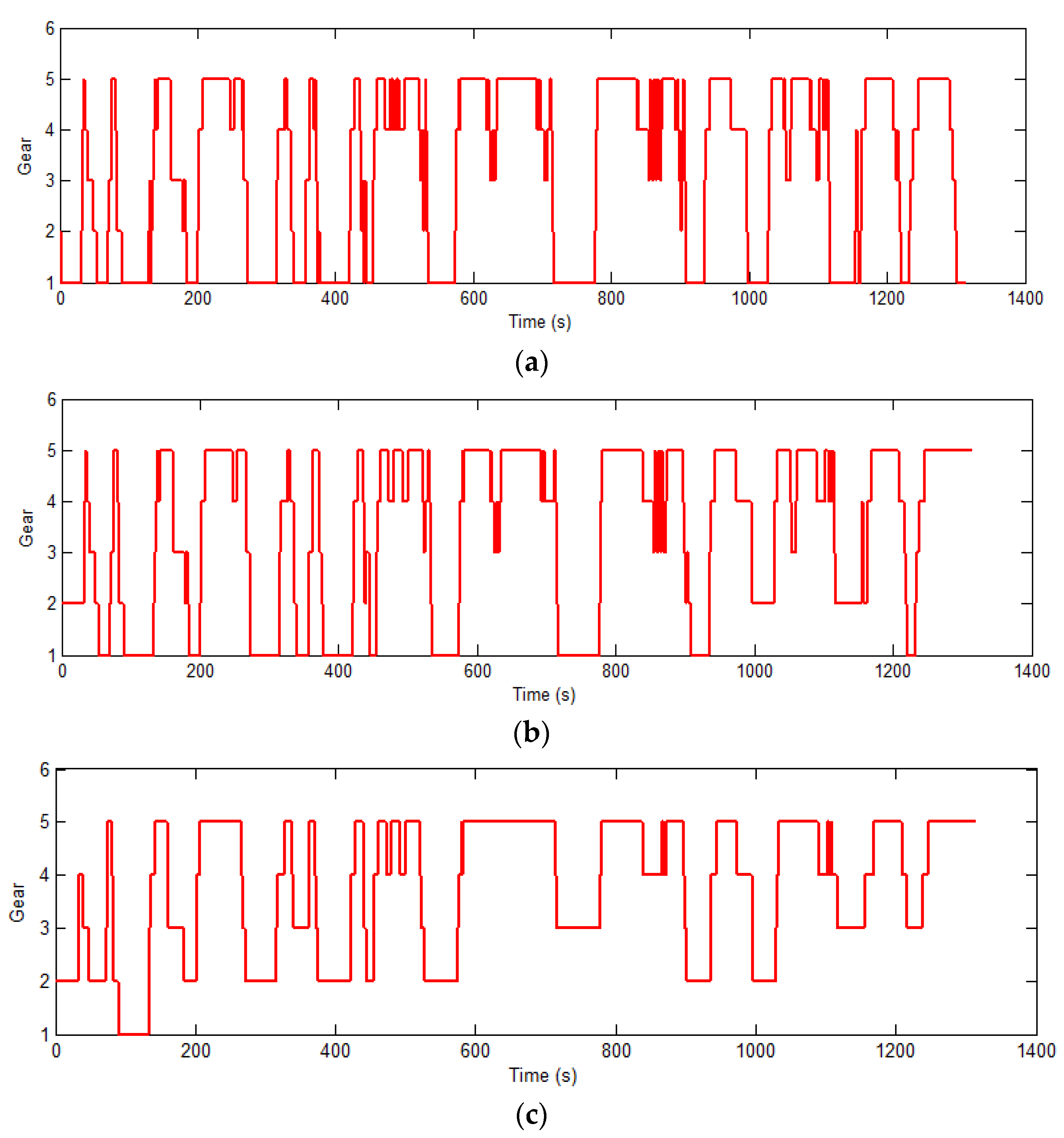
6.1. Simulation Results
6.2. Real Vehicle Test
7. Conclusions
Acknowledgments
Author Contributions
Conflicts of Interest
Abbreviations
| HEV | Hybrid Electric Vehicle |
| AMT | Automated Mechanical Transmission |
| DP | Dynamic Programming |
| SOC | State of Charge |
References
- Sun, Z.; Hebbale, K. Challenges and Opportunities in Automotive Transmission Control. In Proceedings of the 2005 American Control Conference, Portland, OR, USA, 8–10 June 2005; pp. 3284–3289.
- Dorri, M.; Shamekhi, A.H. Design and optimization of a new control strategy in a parallel hybrid electric vehicle in order to improve fuel economy. Proc. Inst. Mech. Eng. Part D J. Automob. Eng. 2011, 225, 747–759. [Google Scholar] [CrossRef]
- Lee, H.; Kirn, H. Improvement in fuel economy for a parallel hybrid electric vehicle by continuously variable transmission ratio control. Proc. Inst. Mech. Eng. Part D J. Automob. Eng. 2005, 219, 43–51. [Google Scholar] [CrossRef]
- Pandian, S.; Gokhale, S.; Ghoshal, A.K. Evaluating effects of traffic and vehicle characteristics on vehicular emissions near traffic intersections. Transp. Res. Part D Transp. Environ. 2009, 14, 180–196. [Google Scholar] [CrossRef]
- Stevanovic, A.; Stevanovic, J.; Zhang, K.; Batterman, S. Optimizing traffic control to reduce fuel consumption and vehicular emissions. Transp. Res. Rec. J. Transp. Res. Board 2009, 2128, 105–113. [Google Scholar] [CrossRef]
- Chen, K.S.; Wang, W.C.; Chen, H.M.; Lin, C.F.; Hsu, H.C.; Kao, J.H.; Hu, M.T. Motorcycle emissions and fuel consumption in urban and rural driving conditions. Sci. Total Environ. 2003, 312, 113–122. [Google Scholar] [CrossRef]
- Tong, H.Y.; Hung, W.T.; Cheung, C.S. On-road motor vehicle emissions and fuel consumption in urban driving conditions. J. Air Waste Manag. Assoc. 2000, 50, 543–554. [Google Scholar] [CrossRef] [PubMed]
- Wu, C.; Zhao, G.; Ou, B. A fuel economy optimization system with applications in vehicles with human drivers and autonomous vehicles. Transp. Res. Part D Transp. Environ. 2011, 16, 515–524. [Google Scholar] [CrossRef]
- Wang, W.; Xi, J.; Chen, H. Modeling and recognizing driver behavior based on driving data: A survey. Math. Probl. Eng. 2014, 2014. [Google Scholar] [CrossRef]
- Anlin, G. Design and Theory of Vehicle Automatic Gear Shifting; China Machine Press: Beijing, China, 1993. [Google Scholar]
- Liu, N. Research on Shift Schedule of Hybrid bus; Jilin University: Changchun, China, 2007. [Google Scholar]
- Yu, H.; Xi, J.; Chen, Y. Research on Shift Schedule of Hybrid Bus Based on Dynamic Programming Algorithm. In Proceedings of the 2012 15th International IEEE Conference on Intelligent Transportation Systems (ITSC), Anchorage, AK, USA, 16–19 September 2012; pp. 1067–1071.
- Ngo, V.; Hofman, T.; Steinbuch, M.; Serrarens, A. Optimal control of the gearshift command for hybrid electric vehicles. IEEE Trans. Veh. Technol. 2012, 61, 3531–3543. [Google Scholar] [CrossRef]
- Hofman, T.; Steinbuch, M.; van Druten, R.; Serrarens, A.F.A. Design of cvt-based hybrid passenger cars. IEEE Trans. Veh. Technol. 2009, 58, 572–587. [Google Scholar] [CrossRef]
- Hofman, T.; Steinbuch, M.; van Druten, R.; Serrarens, A. Rule-based energy management strategies for hybrid vehicles. Int. J. Electr. Hybrid Veh. 2007, 1, 71–94. [Google Scholar] [CrossRef]
- Koot, M.; Kessels, J.T.B.A.; de Jager, B.; Heemels, W.P.M.H.; van den Bosch, P.P.J.; Steinbuch, M. Energy management strategies for vehicular electric power systems. IEEE Trans. Veh. Technol. 2005, 54, 771–782. [Google Scholar] [CrossRef]
- Sciarretta, A.; Guzzella, L. Control of hybrid electric vehicles. IEEE Control Syst. 2007, 27, 60–70. [Google Scholar] [CrossRef]
- Sciarretta, A.; Back, M.; Guzzella, L. Optimal control of parallel hybrid electric vehicles. IEEE Trans. Control Syst. Technol. 2004, 12, 352–363. [Google Scholar] [CrossRef]
- Ambühl, D.; Sundström, O.; Sciarretta, A.; Guzzella, L. Explicit optimal control policy and its practical application for hybrid electric powertrains. Control Eng. Pract. 2010, 18, 1429–1439. [Google Scholar] [CrossRef]
- Xiong, W.; Zhang, Y.; Yin, C. Optimal energy management for a series-parallel hybrid electric bus. Energy Convers. Manag. 2009, 50, 1730–1738. [Google Scholar] [CrossRef]
- Sundstrom, O.; Soltic, P.; Guzzella, L. A transmission-actuated energy-management strategy. IEEE Trans. Veh. Technol. 2010, 59, 84–92. [Google Scholar] [CrossRef]
- Casavola, A.; Prodi, G.; Rocca, G. Efficient gear shifting strategies for green driving policies. In Proceedings of the 2010 American Control Conference, Baltimore, MD, USA, 30 June–2 July 2010; IEEE: New York, NY, USA, 2010; pp. 4331–4336. [Google Scholar]
- Wang, W.; Wang, Q.; Zeng, X. Automated Manual Transmission Shift Strategy for Parallel Hybrid Electric Vehicle; SAE International: New York, NY, USA, 2009. [Google Scholar]
- Qin, G.; Ge, A.; Lee, J.-J. Knowledge-based gear-position decision. IEEE Trans. Intell. Transp. Syst. 2004, 5, 121–125. [Google Scholar] [CrossRef]
- Isermann, R. Mechatronic Systems: Fundamentals; Springer London: London, England, 2007. [Google Scholar]
- Bertsekas, D.P. Dynamic Programming and Optimal Control: Approximate Dynamic Programming; Athena Scientific: New Hampshire, NH, USA, 2012. [Google Scholar]
- Zhu, Z.Q.; Pang, Y.; Chen, J.T.; Xia, Z.P.; Howe, D. Influence of Design Parameters on Output Torque of Flux-Switching Permanent Magnet Machines. In Proceedings of the 2008 IEEE Vehicle Power and Propulsion Conference, VPPC ’08, Harbin, China, 3–5 September 2008; pp. 1–6.
- Hentunen, A.; Lehmuspelto, T.; Suomela, J. Time-domain parameter extraction method for thévenin-equivalent circuit battery models. IEEE Trans. Energy Convers. 2014, 29, 558–566. [Google Scholar] [CrossRef]


| Schedule Type | Fuel Consumption (L/100 km) | Fuel-Efficient (%) |
|---|---|---|
| Traditional two-parameter gear shift schedule | 30.67 | n/a |
| The optimized extracted two-parameter gear shift schedule | 24.54 | 20 |
| DP gear shift schedule | 23.52 | 23.3 |
| Component | Specification | Value | Unit |
|---|---|---|---|
| Engine | Type | Nature gas | - |
| Torque | 678 | N·m | |
| Maximum Power | 172 | kW | |
| Number of Cylinder | 6 | - | |
| Compressed Ratio | 10.5:1 | - | |
| Service Mass | 446 | kg | |
| Motor | Type | Permanent magnet motor | - |
| Rated Power | 75 | kW | |
| Maximum Power | 115 | kW | |
| Rated Torque | 540 | N·m | |
| Base Speed | 1400 | rev/min | |
| Maximum Speed | 3200 | rev/min | |
| Transmission | Gear ratios | 7.05/3.85/2.52/1.59/1.00 | - |
| Final Reducer | Gear ratio | 6.167 | - |
| Battery | Battery Pack Voltage | 288 | V |
| Battery capacity | 8 | Ah | |
| Number of cells | 90 | - | |
| Voltage of cell | 3.2 | V | |
| Vehicle Body | Vehicle Mass | 11,700 | kg |
| Dynamic Tire Radius | 0.478 | m | |
| Air Density | 1.2 | kg/m3 | |
| Front area of vehicle | 6 | m2 | |
| Aerodynamic drag coefficient | 0.7 | - |
| Schedule Type | Simulation Results (L/100 km) | Real Vehicle Results (L/100 km) | Deviation (%) |
|---|---|---|---|
| Conventional two parameters gear shift schedule | 30.67 | 29.5 | 3.8 |
| The optimized two-parameter gear shift schedule | 24.54 | 23.9 | 2.6 |
© 2016 by the authors; licensee MDPI, Basel, Switzerland. This article is an open access article distributed under the terms and conditions of the Creative Commons by Attribution (CC-BY) license (http://creativecommons.org/licenses/by/4.0/).
Share and Cite
Shen, W.; Yu, H.; Hu, Y.; Xi, J. Optimization of Shift Schedule for Hybrid Electric Vehicle with Automated Manual Transmission. Energies 2016, 9, 220. https://doi.org/10.3390/en9030220
Shen W, Yu H, Hu Y, Xi J. Optimization of Shift Schedule for Hybrid Electric Vehicle with Automated Manual Transmission. Energies. 2016; 9(3):220. https://doi.org/10.3390/en9030220
Chicago/Turabian StyleShen, Wenchen, Huilong Yu, Yuhui Hu, and Junqiang Xi. 2016. "Optimization of Shift Schedule for Hybrid Electric Vehicle with Automated Manual Transmission" Energies 9, no. 3: 220. https://doi.org/10.3390/en9030220
APA StyleShen, W., Yu, H., Hu, Y., & Xi, J. (2016). Optimization of Shift Schedule for Hybrid Electric Vehicle with Automated Manual Transmission. Energies, 9(3), 220. https://doi.org/10.3390/en9030220