Article

Aggregator-Based Interactive Charging Management System for Electric Vehicle Charging

1
School of Electrical Engineering, Beijing Jiaotong University, Beijing 100044, China
2
College of Electrical and Information Engineering, Hunan University, Changsha 410082, China
3
Department of Electrical and Computer Engineering, Cornell University, Ithaca, NY 14853, USA
*
Author to whom correspondence should be addressed.
Energies 2016, 9(3), 159; https://doi.org/10.3390/en9030159
Submission received: 6 January 2016 / Revised: 15 February 2016 / Accepted: 25 February 2016 / Published: 4 March 2016

Abstract

:
With the ongoing large-scale implementation of electric vehicles (EVs), the exploration of a more flexible approach to maintain fair interaction between EVs and the power grid is urgently required. This paper presents an aggregator-based interactive charging management scheme adopting interruptible load (IL) pricing, in which the EV aggregator will respond to the load control command of the grid in an EV interactive mode. Charging managements are carried out according to battery state-of-charge and the EV departure time in EV charging stations. A power-altering charging (PAC) control method is proposed to dispatch the EVs charging fairly in a station and guarantee EV owners’ preferences. The method does not require classical iterative procedures or heavy computations; furthermore, it is beneficial for EVs to depart earlier than expected for reasons beyond keeping homeostatic charging. The proposed scheme, which is tested to charge individual EVs well according to its preference, was implemented as part of an “EV Beijing” project. The proposed management scheme provides new insight into EV charging strategy and provides another choice to EV users.

1. Introduction

Modern civilization facilitates our lives while at the same time highlighting such problems as the consumption of fossil fuels, environmental pollution, and so on. As a promising solution for these problems, electric vehicles (EVs) are being vigorously promoted in many countries. The EVs’ implementation on a large scale is a big challenge for the power grid. Research shows that the accumulation of uncontrolled EV loads in space and time will bring regional load imbalance and boost peak load, which will affect the load character of the grid, overload transformers and cables, generate voltage and current impacts, and infect voltage profiles and power quality [1,2,3,4]. Optimized charging management is required to maintain a fair interaction between EVs on a large scale as huge mobile distributed power sources and the grid itself are used to increase the EV access rate. Many proposed schemes show that proper charging management can lessen the impact of EVs on the grid [5,6]; nevertheless, EV charging management should still be further explored for different requirements.
There are three types of EV charging managements based on the relationship between EVs and the power grid, including EV-dominant, grid-dominant, and aggregator-based ones. EV-dominant management contributes to the availability of departure, lowest energy cost and longest battery life of EVs [7]. Because there is a great difference between the demands of each EV, EV-dominant management may cause unpredictable load strikes, which will impair power quality and security in addition to uncontrolled charging [2,4]. Grid-dominant management places more emphasis on the grid, while EVs are regarded as uncertain loads. In addition, load control and optimization algorithms are incorporated into EV charging schemes through forecasting [8,9]. Grid-dominant management is good at minimizing loss and costs, and avoiding constraint violations in the distribution system. Although the driving patterns of EV owners are considered in some cases [5,6], most grid-dominant management concerns multiple EVs in the charging control rather than the demand of a single EV, especially customer preferences and battery life [10]. To coordinate the grid and EVs, distributed optimization algorithms and methods such as decentralized charging control [11], multi-agent-based control [12], and aggregator-based control [13] have been proposed. Based on coordination and combination, aggregator-based management of EV charging can optimize the operation of the power grid, lower power loss, improve voltage profiles, and decrease damage to battery life [14,15,16]. Taken together, the previous managements have been shown to promote the prosperous application of EVs, which brings out new requirements for individual charging preferences.
Aggregator-based charging managements can effectively participate in the power market and utility grid operation [17]. Power market-related algorithms, such as day-ahead optimization and least squares Monte Carlo (LSMC), have been used to dispatch aggregators [18,19]. Price-only controlled aggregator dispatching schemes are indirect load control and are highly sensitive to the choice of a regularization penalty term [20], which may produce unexpected load peak boosts [2]. Furthermore, dynamic pricing is not commonly accepted by customers [21]. As a promising solution, we take the EV aggregator in demand response program [22] and adopt an interruptible load (IL) pricing scheme in this paper. We propose a charging management approach using power control in aggregator and interaction between aggregators and the grid to respond to the load-control command. The EV aggregator interacts with the grid control centre at a certain interval by reporting the charging load range (minimum and maximum) and obtaining the charging power command for the next time interval from the grid control centre. Through the dispatch and control of the charging inside the aggregator, the EV aggregators act as relatively predictable and controllable loads, which participate in the interruptible-load program [23]. EV aggregators sign an IL contract with a utility to reduce their charging power as requested by the utility (through charging power control command), while as an incentive, EV aggregators get a price discount as they adopt interactive charging. It has been proven that with the proper contract price, the benefits to both the utility and the aggregators can be guaranteed [24,25]. In the aggregator, EVs are divided into two categories: the uncontrolled ones with higher charging fees as they decline the dispatch of the aggregator, and the controlled ones with lower charging fee as they participate in load control and grid supply. Although the pricing strategy will affect whether an EV obeys the dispatch or not, it will not influence the proposed mechanism and is not discussed in this paper. In order to guarantee the individual EV preferences (such as departure time, State of charge (SOC), and battery life) of the controlled EVs and fairness among EVs, we build up a power-altering strategy to manage the charging and dispatch of controlled EVs in the aggregator. The system is implemented in an “EV-Beijing” project involving 100 EVs on the campus of Beijing Jiaotong University, China. The proposed charging management are compared with those of the uncontrolled charging and time-altering charging, showing more flexibility and reliability to satisfy the individual needs of each EV in response to the load control command of the grid.
Our approach is not to challenge the existing ones, but to support a useful supplement to them, which is destined to be one more choice for the users. The main contributions of this paper can be summarized as follows:
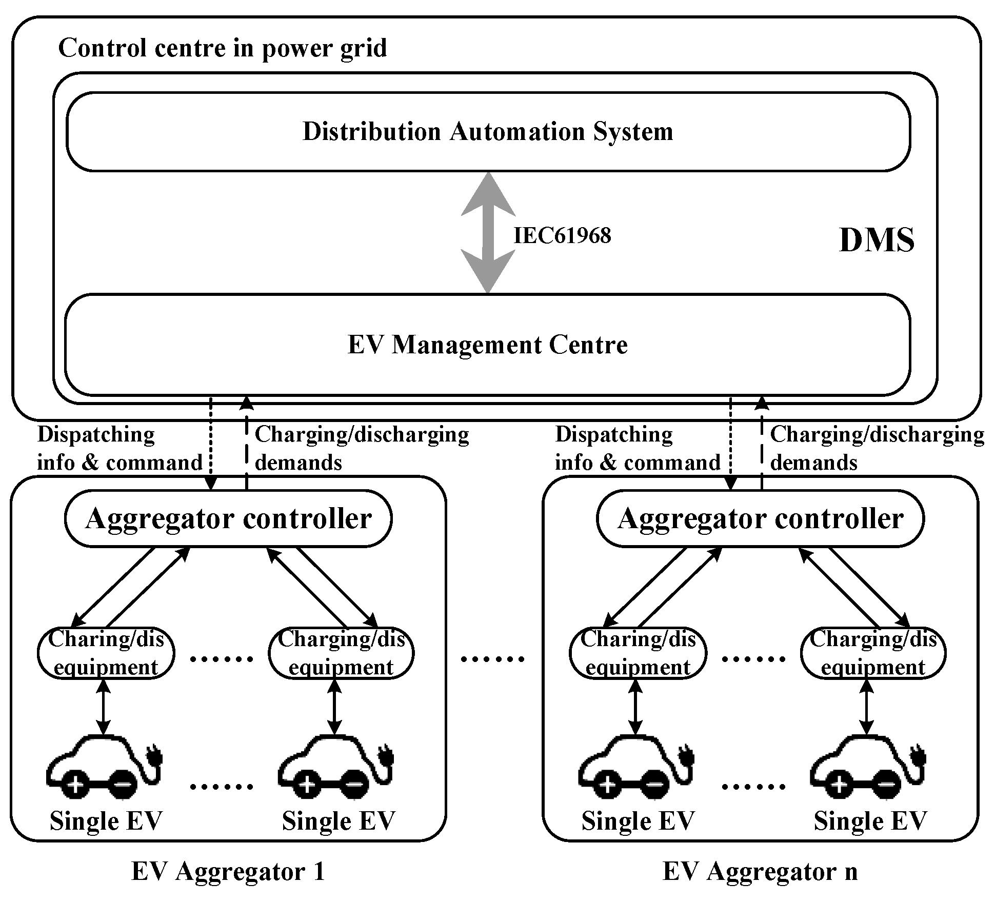
  • An aggregator-based interactive charging management system adopting the IL pricing scheme is proposed in which the charging of EVs in an aggregator are clustered to form a relatively predictable and controllable load via interactive charging management. This will benefit the grid for peak-shifting, valley-filling, and optimal operation.
  • A power-altering charging (PAC) control in aggregator is proposed to guarantee fair charging and EV owners’ preferences such as expected departure time and SOC. Furthermore, EVs that depart earlier than expected can get acceptable charging results. The PAC control does not require classical iterative procedures or heavy computations.

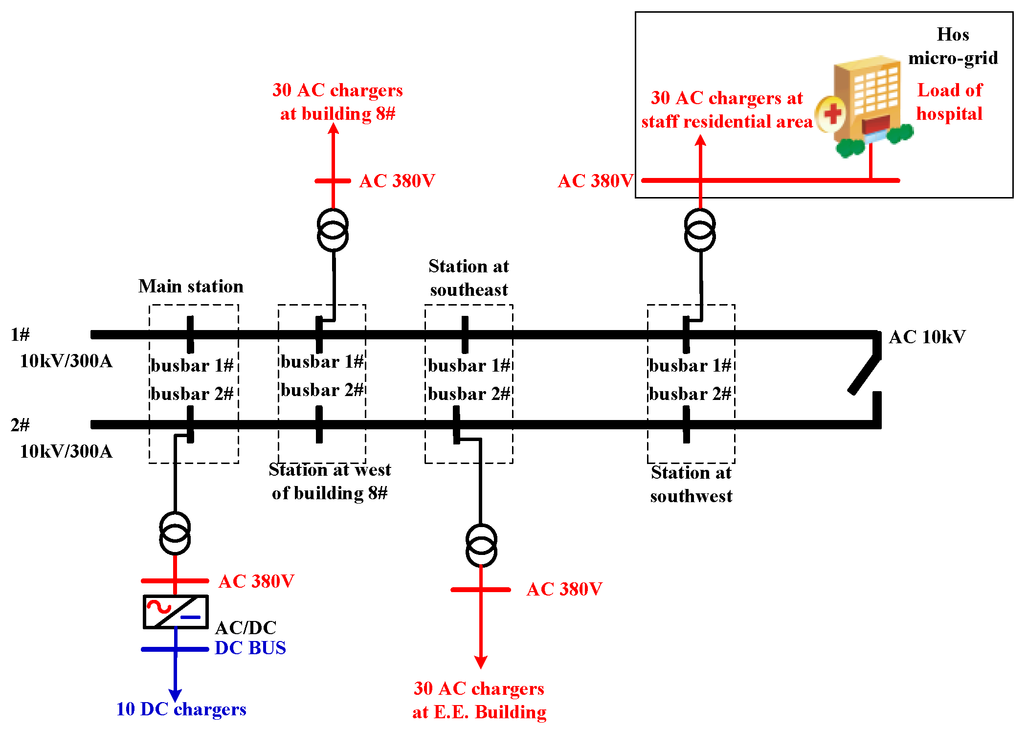
2. Scenario Description

As EVs vary in type, capacity and usage, their charging demands are closely related to human behavior. There are two types of EVs in a charging station: business EVs and private EVs. For business EVs, such as electric buses and electric taxis, their charging schedules are mainly determined by their transportation demands, and they mostly demand fast charging or a battery swap service. Fast charging of business EVs is considered as uncontrolled charging in this paper, while battery swapping in an EV swap station is not considered in this paper. As private vehicles play an important role in commuting (89.4% in 2009 by the National Household Travel Survey [26]), they have a relatively short travel time (the average travel time is 43 min in Beijing [27]) and a relatively long parking time (the average parking time is 8.7 h at the workplace for an 8+ h work day [27]). For private EVs, the charging after working hours can be arranged in a load valley, such as midnight, to prevent peak boost on the regular load peak during the evening hours [7]. On weekends, EVs usually demand to charge as soon as they are plugged in and as fast as possible, which makes them uncontrollable.
In our approach, we manage the scenario of EVs in a charging station during working hours. During working hours, EV charging is mostly clustered in a site such as the campus, factory field or parking lot. For these EVs, some are considered as uncontrolled EVs, such as business EVs, temporary parked EVs (like a visitor’s EV) and EVs that decline the management of the aggregator. Others are considered as controlled EVs, such as private EVs. For controlled EVs, the expected departure time, expected SOC on departure, and cycles of charging are the first level of concern in the charging management for single EVs. Charging demands of all EVs and load-control demands of the power grid are coordinated in the aggregator.

3. Charging Management System

The framework of the charging management system is shown in Figure 1. On arriving, EV owners are permitted to choose controlled or uncontrolled charging. Controlled charged EVs will report their current SOC, the expected departure SOC, and the expected departure time to the aggregator at the station (manually or via smart phone apps). The aggregator controller interacts with the EV Management Center (EVMC) at every interval by reporting the minimum and maximum charging load for the next time interval. The EVMC in the power distribution control center is an advanced application of the distribution management system (DMS). Based on the information from each aggregator controller, the EVMC coordinates with the distribution automation system to get the charging dispatching commands and send them to aggregators for the next time interval.

3.1. Interaction Process of the Charging Power of the Station

During the charging process, the EV aggregator in the station will interact with the EVMC at every time interval by reporting its minimum and maximum charging power value for the next time interval. The EVMC will grant a charging power value in this range according to its dispatching arrangement.
The minimum charging power of a charging station is the total rated power of the controlled EVs that are full-power charging and uncontrolled EVs. Consequently, the minimum charging power of station h at time t, Pforce_t_h, is the forced charging power as in Equation (1):
P force _ t _ h = j = 1 M t _ h P rate _ j M + k = 1 K t _ h P rate _ k U n
where M_t_h is the number of controlled EVs that is are full-power charging in station h at time t, P rate _ j M is the rated charging power of controlled EV j that is full-power charging, K_t_h is the number of uncontrolled EVs in station h at time t, and P rate _ k U n is the rated charging power of uncontrolled EV k.
The maximum charging power of a charging station is the power needed for charging when all the EVs plugged in are charging at full power; therefore, the maximum charging power of station h at time t, Pc_max_t_h, is as in Equation (2):
P c _ max _ t _ h = i = 1 N t _ h P rate _ i
where, Nt_h is the number of EVs plugged in station h at time t and Prate_i is the rated charging power of EV i.
In a distribution grid, there are numbers of charging stations. The EVMC should grant a charging power value between the minimum and maximum charging value of each station according to its dispatching arrangement. There are many dispatching strategies for power distribution such as optimal power strategy, and minimizing peak load strategy. We use a simplified minimizing peak-load dispatching strategy as follows:
Step 1. Obtaining the load curve of the day by load prediction or the load curve of the day before, we can obtain the average value Pav of the load in a period such as from 8 a.m. to 5 p.m. As for the interaction of charging stations with the grid, Pgrid_t is the total load power that the grid expected for the next time interval, which can be obtained based on Pav and the dispatching strategy. Therefore, we obtain the total expected charging power of the grid at time t, Pcharge_grid_t, as in Equation (3):
P charge _ grid _ t = P grid _ t P L _ pre _ t
where PL_pre_t is the load prediction value of the next time interval excluding charging loads.
Step 2. The minimum and maximum charging power of all charging stations at time t sum up to Pc_min_grid_t and Pc_max_grid_t as in Equation (4):
{ P c _ min _ grid _ t = h = 1 H P force _ t _ h P c _ max _ grid _ t = h = 1 H P c _ max _ t _ h
where H is the number of charging stations, Pforce_t_h is the minimum power, and Pc_max_t_h is the maximum power that station h reported at time t.
Step 3. The charging power of station h that the grid granted, Pc_grant_t_h, is as in Equation (5):
P c _ grant _ t _ h = { P force _ t _ h ,  if  P charge _ grid _ t P c _ min _ grid _ t ; P force _ t _ h + ( P charge _ grid _ t - P c _ min _ grid _ t ) × P c _ max _ t _ h / P c _ max _ grid _ t  if  P c _ min _ grid _ t < P charge _ grid _ t < P c _ max _ grid _ t ; P c _ max _ t _ h ,  if  P charge _ grid _ t P c _ max _ grid _ t

3.2. Charging Dispatching Formulation in an Aggregator

As for each time interval, the aggregator will get a granted charging power and dispatch it among the EVs in the station. Different goals will result in different dispatching schemes in the station. In our approach, as in Equation (6), we aim to maximize the number of EVs charging and minimize the maximal differences between the current SOC and the expected departure SOC of EVs in the station for fair charging.
  • Objective Function: For EVs from 1 to Nt in time interval t, the objective functions are as in Equation (6):
    { max  A = i = 1 N t I i _ t min max ( Δ SOC t )
    where Ii_t is the binary variable of charging status of EV i at time t, Ii_t = 1 means EV i is charging, and Ii_t = 0 means not charging. Nt is the number of EVs plugged in at time t. Function “min max(ΔSOCt)” means minimizing the maximal ΔSOCt, ΔSOCt = {ΔSOC1_t, ΔSOC2_t,……, ΔSOCN_t}. ΔSOCi_t = SOCdep_i − SOCi_t is the difference between the expected departure SOC value of EV i ( SOCdep_i) and the current SOC value of EV i (SOCi_t) at time t.
  • Control Variables: For EVs at time t, the charging status vector It = {I1_t, I2_t,……, IN_t} and the charging power vector Pt = {P1_t, P2_t,……, PN_t} are control variables, where Pi_t is the charging power of EV i at time t.
  • Constraints: The constraints are as in Equations (7)–(11).
Charging status constraint.
I k _ t U n = 1
where, I k _ t U n is the charging status variable of uncontrolled EV k at time t. This constraint implies that uncontrolled EVs must be charging until they reach their expected SOC.
Charging time constraint.
t dep _ i t > d char _ i
where tdep_i is the expected departure time of EV i, t is the current time, and dchar_i is the duration needed for the EV i to be charged at full power to its expected SOC.
Charging power constraint.
i = 1 N I i _ t P c _ i _ t = P c _ grant _ t
0 < P c _ i _ t P rate _ i
P c _ k _ t U n = P rate _ k U n
where, for time interval t, Pc_i_t is the charging power of EV i, Pc_grant_t is the total charging power of the station, Prate_i is the rated charging power of EV i, and P c _ k _ t U n is the charging power of uncontrolled EV k.

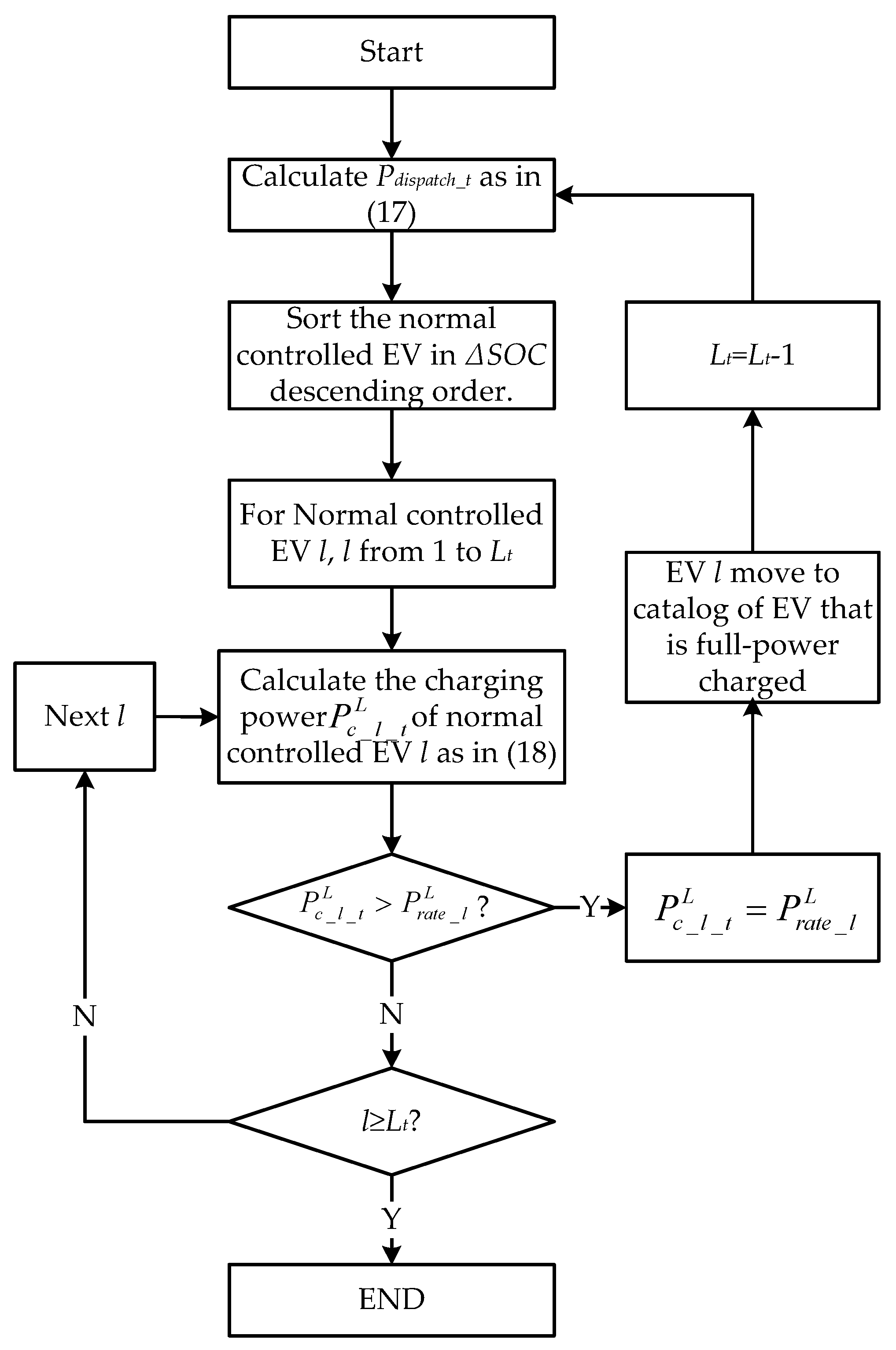
3.3. Power-Altering Charging Control

The EV aggregator interacts with the EVMC at every interval and gets the charging power command Pc_grant_t. This power (Pc_grant_t) is usually between the minimal charging power as in Equation (1) and the maximal charging power of the station as in Equation (2). The dispatching of Pc_grant_t in an aggregator in each time interval t requires a fast solution, whereas with the objective functions in Equation (6) and constraints in Equations (7)–(11), it is a mixed-integer and minmax problem, to which there still is not a common global optimal solution [28,29]. Artificial intelligence (AI) algorithms such as particle swarm optimization (PSO) and simulated annealing (SA) can be used in aggregator inner coordination [30,31], while, in practice, AI algorithms will take numerous iterations and require large calculation resources for a fast solution. This will make it complicated to implement an aggregator which is usually deployed in a charging station. In this paper, we propose a fair charging control called PAC control as a sub-optimal solution. The PAC control charges an EV according to its departure time and SOC, and needs few iterations. The dispatching process is as follows:
  • For Equation (6), to maximize the amount of EVs charging, control variable It is as Equation (12):
    It = {1,1,…,1}
    means all EVs plugged in the charging station will be charged. This will satisfy constraint (7).
  • For constraint (8), in each time interval, those EVs whose departure time is approaching, as in Equation (13), are treated as controlled EVs that are full-power charging:
    t dep _ i t d char _ i + Δ T
    where ΔT is a time constant, and other symbols are the same as in Equation (8).
  • For control variable Pt, Pt is categorized to charging power of uncontrolled EVs, EVs that are full-power charging, and normal charging EVs as in Equation (14).
    P t = { P c _ 1 _ t U n , ... , P c _ K t _ t U n , P c _ 1 _ t M , ... , P c _ M t _ t M , P c _ 1 _ t L , ... , P c _ L t _ t L }
    where { P c _ 1 _ t U n , ... , P c _ K t _ t U n } is the charging power series of uncontrolled EVs, Kt is the number of uncontrolled EVs at time t, { P c _ 1 _ t M , ... , P c _ M t _ t M } is the charging power series of controlled EVs that are full-power charging, Mt is the number of controlled EVs that are full-power charging at time t, { P c _ 1 _ t L , ... , P c _ L t _ t L } is the charging power series of normal controlled EVs, Lt is the number of normal controlled EVs at time t.
    i) 
    Charging power of uncontrolled EV k is as in Equation (15). This will satisfy constraint (11).
    P c _ k _ t U n = P rate _ k U n k = 1 , ... , K t
    ii) 
    Charging power of controlled EV j that is full-power charging is as in Equation (16):
    P c _ j _ t M = P rate _ j M j = 1 , ... , M t
    iii) 
    The power that can be dispatched for normal charging EVs, Pdispatch_t, is as in Equation (17):
    P dispatch _ t = P c _ grant _ t k = 1 K t P c _ k _ t U n j = 1 M t P c _ j _ t M
For normal charging EVs, to minimize the maximal ΔSOC with constraints Equation (9) and (10), we dispatch their charging power according to their SOC for fair charging as in Figure 2. We first get the Pdispatch_t based on Equation (17), then sort the normal controlled EVs in descending order based on their ΔSOC. For the sorted EVs, from 1 to Lt, we calculate their charging power as in Equation (18); if the value is bigger than its rated charging power, this EV will be moved to the full-power catalog, and the whole process will starts from the beginning.
P c _ l _ t L = P dispatch _ t × ( Δ SOC l _ t L Δ SOC max L P rate _ l L ) / l = 1 L t ( Δ SOC l _ t L Δ SOC max L P rate _ l L ) , l = 1 , ... , L t
where, P c _ l _ t L is the charging power of normal controlled EV l at time t, Δ SOC l _ t L = SOC dep _ l L SOC l _ t L , SOC dep _ l L is the expected departure SOC value and SOC l _ t L is the current SOC value of normal controlled EV l, Δ SOC max L is the maximum value of { Δ SOC l _ t L | l = 1 , ... , L t } , and P rate _ l L is the rated charging power of normal controlled EV l.

4. Results

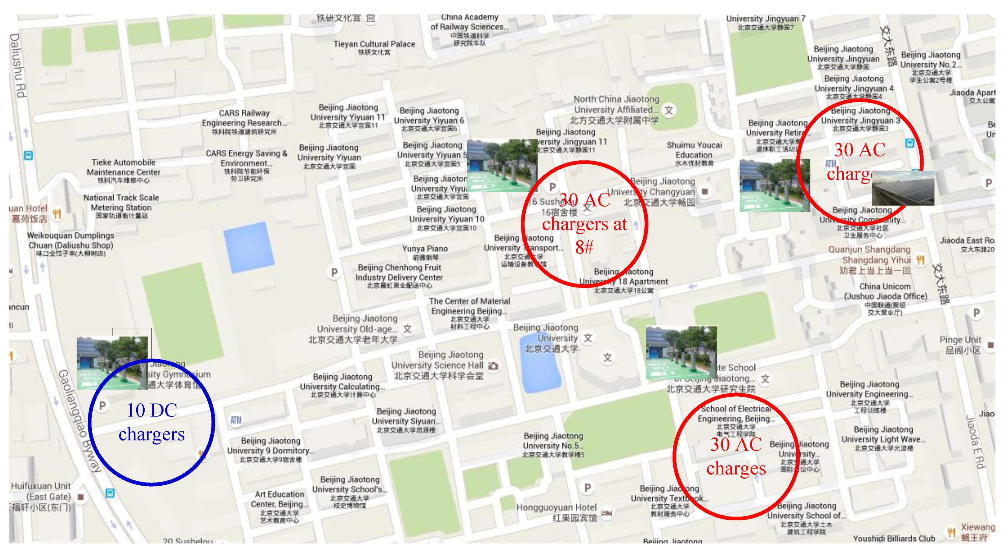
4.1. Introduction of the Experiments

As part of the “EV Beijing: Fellow Project,” a campus EV experimental platform was established with the support of the “Beijing Municipal Science & Technology commission.” It has been in operation for over 700 days since December 2013. The platform is made up of 100 chargers in Beijing Jiaotong University (BJTU), including 30 AC chargers located at building No. 8, 30 AC chargers located at the E.E. building, 30 AC chargers located at the staff residential area near the hospital and 10 DC chargers located near the west gate. The geographical placement of the chargers is shown in Figure 3.
The electric wiring diagram of the devices is shown in Figure 4. The AC 10 kV framework is formed by two “hand-in-hand” cables connecting the EVs and other loads. Thirty AC chargers near the hospital were connected with the hospital load in a micro-grid. Other normal loads in BJTU are not shown in Figure 4. The rated power of an AC charger is 3 kW and the rated power of a DC charger is 15 kW. One hundred E150 EVs manufactured by BAIC Motor Corporation China were involved in the project, and individuals could rent them for daily usage. An E150 can be charged via two methods: DC 330V/50A, 1–2 h for full charge, and AC 220V/12A, 4–6 h for full charge.
The proposed charging management strategies were implemented in the EV control centre on the campus. The raw data of the daily load curve is derived from the daily SCADA data. For the charging management strategies proposed, ΔT in (13) is 30 min (0.5 h). The electricity price that utility grid charged for the station is 0.08 $/kWh, 80% of the commercial electricity price in Beijing. The charging price for an uncontrolled EV is 0.15 $/kWh, and the charging price for a controlled EV is 0.11 $/kWh. We compared the uncontrolled charging, well-known time-altering charging, and proposed PAC in three similar work days. The uncontrolled charging signifies that EVs will be charging as they are plugged in. The time-altering charging signifies that EVs are charging at full power; while not all EVs are charged simultaneously, the charging start and end time of EVs will change to meet the total charging power command of the station.

4.2. Results Analysis

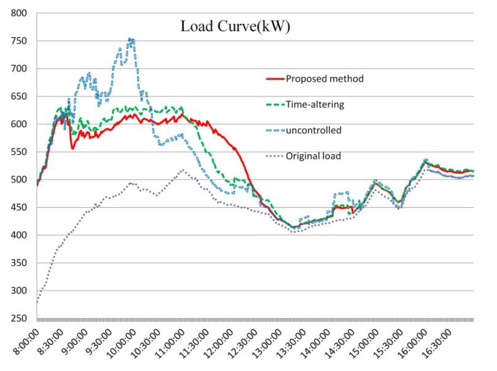
4.2.1. Effects of Charging Control on the Load Curve

Figure 5 shows the typical load curves during working hours, the original load curve without the EV charging load, the load curve with uncontrolled EV charging, the load curve with proposed EV PAC and the load curve with EV time-altering charging. Table 1 shows the peak loads, valley loads and the variances of the four curves. It can be seen that uncontrolled EV charging will greatly increase the peak load and load variance of load curve. When compared with uncontrolled charging, interactive charging makes the charging power of a station relatively controllable, so that both the proposed charging control and the time-altering charging control can restrain the fluctuation of the load curve. The effect of restraint depends on the load control command of the distribution dispatching. On comparing the proposed method and the time-altering method in detail, we note that the proposed method has relatively better performance than the time-altering method. This was caused by the total charging power where time-altering control is ladder-shaped, and when the expected charging power Pc_grant_t is between two ladder steps, the actual charging power will be the upper ladder, making it bigger than the expected one.

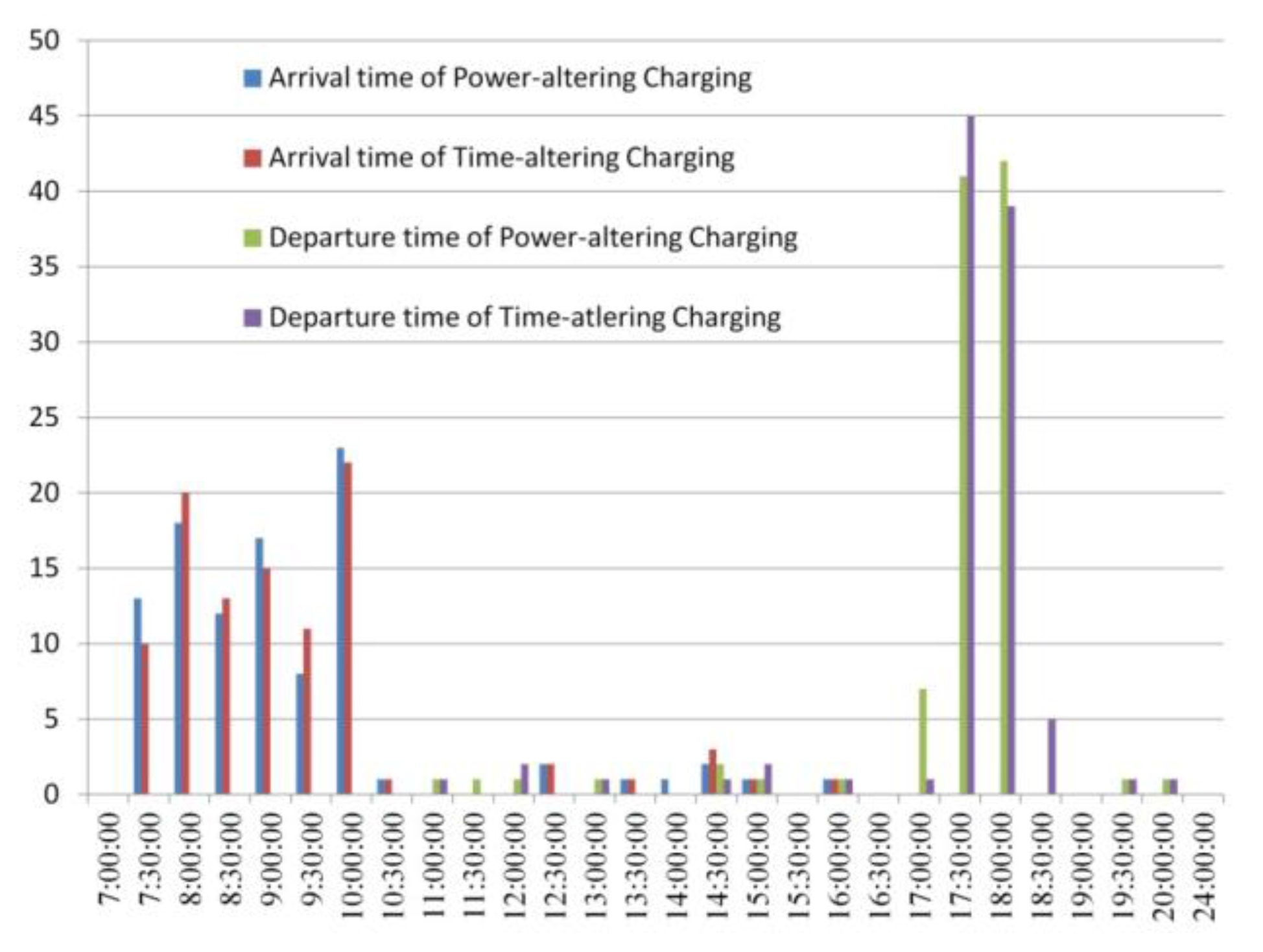
4.2.2. Effects of Charging Control Methods on EVs

Figure 6 shows the EV arrival and departure time distribution in the PAC case and time-altering case. It can be seen that EVs arrived mostly at about 7–10 a.m., and departed mostly at about 5–6:30 p.m., although some arrived later or departed earlier. Table 2 shows the SOC distribution statistics of the arrival SOC and the departure SOC in the two cases. All EVs’ expected departure SOCs are set to 0.95. It can be seen that most of the EVs’ SOC are guaranteed to their expected value when they depart. Detailed information can be obtained from the additional Excel files. The four exception EVs are EV number 22, 31, 33, and 71.
Table 3 shows the charging details of EV number 22, 31, 33, and 71. EV 22 and 33 arrived in the afternoon and there was not enough charging time to charge them to the expected SOC. For EV 31 and 71, both departed earlier than expected, and PAC had a better charging result. This is because the power-altering method can charge all the EVs plugged in continually and fairly. Although the time-altering method can charge EVs at full power, the charging durations of EVs in this method may vary greatly.

5. Conclusions

The coordination of the grid, charging station and single EVs are considered in this paper. This paper proposes an interactive charging management strategy for the relationship between charging stations and the grid by means of an aggregator. A PAC control method is proposed for the distribution of charging power in an aggregator. The proposed strategy has been implemented and tested in a work day scenario as part of an “EV Beijing” project at BJTU involving 100 commuting private EVs since late 2013.
The main conclusions of this paper are as follows:
  • The interactive charging strategy provides a way for EV charging loads clustered in an aggregator to respond to the load-control command of the grid. This will make the EV charging loads predictable and controllable to some extent, and improve the flexibility and reliability of the grid operation.
  • The proposed PAC control method can dispatch charging power fairly in an aggregator and guarantee the EV owner’s preferences. Furthermore, the PAC method has good charging results for EVs departing earlier than expected.
The proposed strategy in this paper was implemented in the work day scenario. It can also be implemented in other scenarios with EVs’ charging clustered. The current research supports a promising method for facilitating large-scale EVs accessing the power grid by coordinating the interaction between the charging station and the power grid. Proper management of EVs in the station can be beneficial for both the grid and EVs.

Acknowledgments

The work was supported by National Natural Science Foundation of China (51477006).

Author Contributions

Mingchao Xia and Canbing Li conceived and designed the experiments; Qingying Lai and Yajiao Zhong performed the experiments; Mingchao Xia and Hsiao-Dong Chiang conceived the algorithm and analyzed the data, Mingchao Xia wrote the paper.

Conflicts of Interest

The authors declare no conflict of interest.

Abbreviations

The following abbreviations are used in this manuscript:
EVElectric vehicle
ILInterruptible load
SOCState of charge
EVMCElectric vehicle management centre
DMSDistribution management system
SCADASupervisory control and data acquisition
AIArtificial intelligence
PACPower-altering charging

Nomenclatures

dchar_iDuration needed for EV i to be charged in full power to its expected SOC
Ii_tCharging status of EV i at time t
I k _ t U n Charging status of uncontrolled EV k at time t
Kt_hNumber of uncontrolled EVs in station h at time t
LtNumber of normal controlled EVs at time t
Mt_hNumber of controlled EVs that are full-power charging in station h at time t
Nt_hNumber of EVs connected in station h at time t
Pforce_tForced charging power of aggregator at time t
Pc_max_tMaximum charging power of aggregator at time t
Pcharge_grid_tTotal expected charging power of the grid at time t
PL_pre_tLoad prediction value of the next time interval t excluding charging loads
Pc_i_tCharging power of EV i at time t
Pc_grant_tTotal charging power of the station at time t
Prate_iRated charging power of EV i
P rate _ j M Rated charging power of controlled EV j that is full-power charging
P rate _ k U n Rated charging power of uncontrolled EV k
P c _ k _ t U n Charging power of uncontrolled EV k at time t
P c _ l _ t L Charging power of normal controlled EV l at time t
SOCdep_iExpected departure SOC value of EV i
SOCi_tCurrent SOC value of EV i at time t
tCurrent time
tdep_iExpected departure time of EV i
ΔSOCtSerial of ΔSOCi_t
ΔSOCi_tDifference of expected departure SOC and current SOC of EV i at time t
ΔTTime constant

References

  1. Fernandez, L.P.; Roman, T.G.S.; Cossent, R.; Domingo, C.M.; Frias, P. Assessment of the impact of plug-in electric vehicles on distribution networks. IEEE Trans. Power Syst. 2011, 26, 206–213. [Google Scholar] [CrossRef]
  2. Hilshey, A.D.; Hines, P.D.H.; Rezaei, P.; Dowds, J.R. Estimating the impact of electric vehicle smart charging on distribution transformer aging. IEEE Trans. Smart Grid 2013, 4, 905–913. [Google Scholar] [CrossRef]
  3. Calderaro, V.; Galdi, V.; Graber, G.; Graditi, G.; Lamberti, F. Impact assessment of energy storage and electric vehicles on smart grids. In Proceedings of the 2014 9th International Electric Power Quality and Supply Reliability Conference (PQ 2014), Rakvere, Estonia, 11–13 June 2014.
  4. Papadopoulos, P.; Skarvelis-Kazakos, S.; Grau, I.; Cipcigan, L.M.; Jenkins, N. Electric vehicles' impact on british distribution networks. Electr. Syst. Transp. IET 2012, 2, 91–102. [Google Scholar] [CrossRef]
  5. Leemput, N.; Geth, F.; Van Roy, J.; Olivella-Rosell, P.; Driesen, J.; Sumper, A. MV and LV residential grid impact of combined slow and fast charging of electric vehicles. Energies 2015, 8, 1760–1783. [Google Scholar] [CrossRef] [Green Version]
  6. Aziz, M.; Oda, T.; Mitani, T.; Watanabe, Y.; Kashiwagi, T. Utilization of electric vehicles and their used batteries for peak-load shifting. Energies 2015, 8, 3720–3738. [Google Scholar] [CrossRef]
  7. Richardson, P.; Flynn, D.; Keane, A. Optimal charging of electric vehicles in low-voltage distribution systems. IEEE Trans. Power Syst. 2012, 27, 268–279. [Google Scholar] [CrossRef]
  8. Xydas, E.S.; Marmaras, C.E.; Cipcigan, L.M.; Hassan, A.S.; Jenkins, N. Forecasting electric vehicle charging demand using support vector machines. In Proceedings of the 2013 48th International Universities' Power Engineering Conference (UPEC), Dublin, UK, 2–5 September 2013.
  9. Chis, A.; Lunden, J.; Koivunen, V. Scheduling of plug-in electric vehicle battery charging with price prediction. In Proceedings of the 2013 4th IEEE/PES Innovative Smart Grid Technologies Europe (ISGT EUROPE), Lyngby, Denmark, 6–9 October 2013.
  10. Luo, Z.W.; Hu, Z.C.; Song, Y.H.; Xu, Z.W.; Lu, H.Y. Optimal coordination of plug-in electric vehicles in power grids with cost-benefit analysis-part II: A case study in china. IEEE Trans. Power Syst. 2013, 28, 3556–3565. [Google Scholar] [CrossRef]
  11. Ma, Z.J.; Callaway, D.; Hiskens, I. Decentralized charging control for large populations of plug-in electric vehicles. In Proceedings of the IEEE Transactions on Control Systems Technology, Atlanta, GA, USA, 15–17 December 2010; pp. 67–78.
  12. Olivella-Rosell, P.; Villafafila-Robles, R.; Sumper, A.; Bergas-Jané, J. Probabilistic agent-based model of electric vehicle charging demand to analyse the impact on distribution networks. Energies 2015, 8, 4160–4187. [Google Scholar] [CrossRef] [Green Version]
  13. Bandyopadhyay, A.; Wang, L.F.; Devabhaktuni, V.K.; Green, R.C. Aggregator analysis for efficient day-time charging of plug-in hybrid electric vehicles. In Proceedings of the 2011 Ieee Power And Energy Society General Meeting, San Diego, CA, USA, 24–29 July 2011.
  14. Karfopoulos, E.L.; Marmaras, C.E.; Hatziargyriou, N. Charging control model for electric vehicle supplier aggregator. In Proceedings of the 2012 3rd IEEE PES Innovative Smart Grid Technologies Europe (Isgt Europe), Berlin, Germany, 14–17 October 2012.
  15. Sortomme, E.; Hindi, M.M.; MacPherson, S.D.J.; Venkata, S.S. Coordinated charging of plug-in hybrid electric vehicles to minimize distribution system losses. IEEE Trans. Smart Grid 2011, 2, 198–205. [Google Scholar] [CrossRef]
  16. He, Y.F.; Venkatesh, B.; Guan, L. Optimal scheduling for charging and discharging of electric vehicles. IEEE Trans. Smart Grid 2012, 3, 1095–1105. [Google Scholar] [CrossRef]
  17. Bessa, R.J.; Matos, M.A. Economic and technical management of an aggregation agent for electric vehicles: A literature survey. Eur. Trans. Electr. Power 2012, 22, 334–350. [Google Scholar] [CrossRef]
  18. Bessa, R.J.; Matos, M.A. Optimization models for EV aggregator participation in a manual reserve market. IEEE Trans. Power Syst. 2013, 28, 3085–3095. [Google Scholar] [CrossRef]
  19. Di Silvestre, M.L.; Sanseverino, E.R.; Zizzo, G.; Graditi, G. An optimization approach for efficient management of ev parking lots with batteries recharging facilities. J. Ambient Intell. Humaniz. Comput. 2013, 4, 641–649. [Google Scholar] [CrossRef]
  20. Xi, X.; Sioshansi, R. Using price-based signals to control plug-in electric vehicle fleet charging. IEEE Trans. Smart Grid 2014, 5, 1451–1464. [Google Scholar] [CrossRef]
  21. Alexander, B.R. Dynamic pricing? Not so fast! A residential consumer perspective. Electr. J. 2010, 23, 39–49. [Google Scholar] [CrossRef]
  22. Falvo, M.C.; Graditi, G.; Siano, P. Electric vehicles integration in demand response programs. In Proceedings of the 2014 International Symposium on Power Electronics, Electrical Drives, Automation and Motion (SPEEDAM), Ischia, Italy, 18–20 June 2014; pp. 548–553.
  23. Yu, C.W.; Zhang, S.; Chung, T.S.; Wong, K.P. Modelling and evaluation of interruptible-load programmes in electricity markets. IEE Proc. Gener. Transm. Distrib. 2005, 152, 581–588. [Google Scholar] [CrossRef]
  24. Chung, T.S.; Zhang, S.H.; Yu, C.W.; Wong, K.P. Electricity market risk management using forward contracts with bilateral options. IEE Proc. Gener. Transm. Distrib. 2003, 150, 588–594. [Google Scholar] [CrossRef]
  25. Fahrioglu, M.; Alvarado, F.L. Designing incentive compatible contracts for effective demand management. IEEE Trans. Power Syst. 2000, 15, 1255–1260. [Google Scholar] [CrossRef]
  26. Santos, A.; McGuckin, N.; Nakamoto, H.Y.; Gray, D.; Liss, S. Summary of travel trends: 2009 national household travel survey; U.S. Department of Transportation Federal Highway Administration: Washington, DC, USA, 2011. [Google Scholar]
  27. Autonavi company China, analysis report of main cities in China, year 2015. Available online: http://download-report.cn-hangzhou.oss-pub.aliyun-inc.com/download%2F2015%E5%B9%B4%E5%BA%A6%E4%B8%AD%E5%9B%BD%E4%B8%BB%E8%A6%81%E5%9F%8E%E5%B8%82%E4%BA%A4%E9%80%9A%E5%88%86%E6%9E%90%E6%8A%A5%E5%91%8A-final.pdf (accessed on 20 January 2016).
  28. Frenk, J.B.G.; Kassay, G.; Kolumban, J. On equivalent results in minimax theory. Eur. J. Oper. Res. 2004, 157, 46–58. [Google Scholar] [CrossRef]
  29. Ehrgott, M.; Ide, J.; Schoebel, A. Minmax robustness for multi-objective optimization problems. Eur. J. Oper. Res. 2014, 239, 17–31. [Google Scholar] [CrossRef]
  30. Sousa, T.; Vale, Z.; Carvalho, J.P.; Pinto, T.; Morais, H. A hybrid simulated annealing approach to handle energy resource management considering an intensive use of electric vehicles. Energy 2014, 67, 81–96. [Google Scholar] [CrossRef]
  31. Hajforoosh, S.; Masoum, M.A.S.; Islam, S.M. Real-time charging coordination of plug-in electric vehicles based on hybrid fuzzy discrete particle swarm optimization. Electr. Pow Syst. Res. 2015, 128, 19–29. [Google Scholar] [CrossRef]
Figure 1. Framework of the electric vehicles (EVs) charging management system.
Energies 09 00159 g001
Figure 2. Charging power calculation flow for normal EV charging.
Energies 09 00159 g002
Figure 3. Geographical placement of EV chargers.
Energies 09 00159 g003
Figure 4. Electric wiring diagram of the “EV Beijing” project in BJTU.
Energies 09 00159 g004
Figure 5. Load curve comparison of different charging control methods.
Energies 09 00159 g005
Figure 6. EV arrival and departure time for different charging control methods.
Energies 09 00159 g006
Table 1. Peak and valley values and variance of load curves.
LoadPeak (kW)Valley (kW)Variance
Original load518.27280.331988.8
Uncontrolled754.37411.937453.2
Time-altering631.97414.295047.7
Proposed method617.91414.294514.3
Table 2. State of charge (SOC) distribution statistics.
SOC Range (%)Arrival SOC of Power-AlteringArrival SOC of Time-AlteringDeparture SOC of Power-AlteringDeparture SOC of Time-Altering
250000
300000
351100
400000
452200
503300
550000
601100
65121100
70242301
75172000
80111611
85211310
908822
95029290
1000046
Table 3. Charging details of sample EVs.
EV No.Power-Altering Charging (PAC)
Arrival SOC (%)Departure SOC (%)Arrival TimeDeparture Time
22629213:5817:00
31488509:1411:25
33768915:4017:00
71687709:4210:34
EV No.Time-Altering Charging
Arrival SOC (%)Departure SOC (%)Arrival timeDeparture time
22639214:0317:04
31508009:1511:30
33768915:4417:03
71707009:4710:33

